S15: Real Time Brake Assist (RTBA)
Contents
Grading Criteria
- How well is Software & Hardware Design described?
- How well can this report be used to reproduce this project?
- Code Quality
- Overall Report Quality:
- Software Block Diagrams
- Hardware Block Diagrams
- Schematic Quality
- Quality of technical challenges and solutions adopted.
Real Time Brake Assist (RTBA)
Abstract
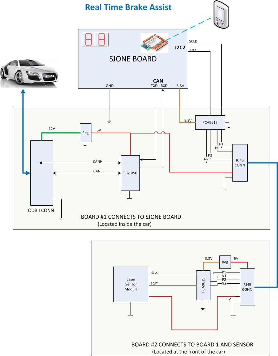
Real time brake assist is an automotive application that helps the user in calculating a safe braking distance with respect to the car in the front. The system makes use of a LiDAR sensor for judging the car’s proximity to the car ahead of it and uses the diagnostic port (OBDII) to pull up the car’s current speed from the ECU. Based on the collected data, it will calculate the safe braking distance and will provide visual indicators for the same.
Objectives & Introduction
What we would like to accomplish is the following:
- Provide a user friendly solution to brake assistance by analyzing car's data through OBD-II.
- Lidar to detect distance.
- OBD-II interface with SJSU One Board.
- Special I2C circuitry for wiring the lidar from the front of the car to inside of the car.
- Provide a simple mobile application which reads the OBD-II data through bluetooth as additional feature to the braking solution. It would provide the following indicators:
- Car Speed(mph)
- Braking Distance(ft)
- Proximity(ft)
- Safety Warning
- Additional Features:
- TBD
Team Members & Responsibilities
- Sahil Kataria
- Architecture Design, Hardware & Software Development, Integration
- Julio Fuentes
- I2C Communication, Hardware Development
- Shaw Ken Chang
- Android App Development using Bluetooth module, System Integration, new features.
- Naghma Anwar
- CAN Communication, Software Development
Schedule
Show a simple table or figures that show your scheduled as planned before you started working on the project. Then in another table column, write down the actual schedule so that readers can see the planned vs. actual goals. The point of the schedule is for readers to assess how to pace themselves if they are doing a similar project.
| Week # | Start Date | End Date | Task | Status | Result |
|---|---|---|---|---|---|
| 1 | 03/10/15 | 03/16/15 |
|
Completed |
|
| 2 | 03/17/15 | 03/23/15 |
|
Completed |
|
| 3 | 03/24/15 | 03/30/15 |
|
Completed |
|
| 4 | 03/31/15 | 04/06/15 |
|
Completed |
|
| 5 | 04/07/15 | 04/13/15 |
|
Completed |
|
| 6 | 04/14/15 | 04/20/15 |
|
Ongoing |
|
| 7 | 04/21/15 | 04/27/15 |
|
Completed |
|
| 8 | 04/28/15 | 05/04/15 |
|
Ongoing |
|
| 9 | 05/05/15 | 05/11/15 |
|
Ongoing | |
| 10 | 05/12/15 | 05/25/15 |
|
Scheduled |
Parts List & Cost
Give a simple list of the cost of your project broken down by components. Do not write long stories here.
| Item# | Part Desciption | Vendor | Part Number | Qty | Cost |
|---|---|---|---|---|---|
| 1 | LIDAR Lite | sparkfun.com | SEN-13167 | 1 | $89.95 |
| 2 | SJOne Board | SCE | 1 | $80.00 | |
| 3 | I2C Diff Buffer | NXP | PCA9615DPJ | 2 | $2.99 |
| 4 | CAN Trasceiver | Philips | TJA1050T | 1 | $1.03 |
| 5 | 12V-5V DC-DC REG | Murata | 7805SR-C | 1 | $9.90 |
| 6 | 3.3V LDO REG | ON Semiconductor | NCP4683DSQ33T1G | 1 | $0.92 |
| 7 | Prototype board | Twin Industries | 800-45 | 1 | $12.99 |
Design & Implementation
The design section can go over your hardware and software design. Organize this section using sub-sections that go over your design and implementation.
Hardware Design
The Real Time Break assist hardware consists of the three boards. The SJ-ONE board provides the LPC1758 ARM based CPU with the integrated CAN and I2C interface controllers used for communication. The second board referred as “Board #1” in the hardware diagram provides the CAN PHY, 12V to 5V voltage regulation and the I2C differential driver. The third board is located in the front of the car and provides power and proper I2C connectivity to the Linder laser distance sensor. The user interface is implemented through an android based device that connects to the SJ-ONE board through a Bluetooth module.
Hardware Diagram
Hardware Interface
Interface to Lidar Laser Distance Sensor
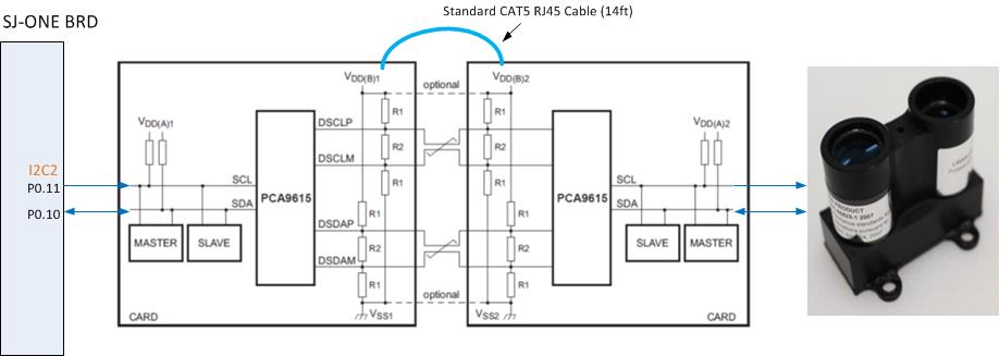
The Linder laser distance sensor requires 5V and I2C interface operating at a maximum rate of 100Kbps for communication. To provide a reliable and low cost communication to the sensor, a PCA9615 differential driver was chosen. The PCA9615 provides the noise immunity and capability to drive long cables necessary for this application. For cable connectivity, a standard CAT5 RJ45 cable was used because of its low cost and twisted pair connectivity for differential signals. The diagram below shows the connectivity of the differential pairs. In order to provide the maximum differential swing, VDDB1 and VDDB2 should be connected to 5V and use 120ohms for R1 and 60 ohms for R2. VDDA1 and VDDA2 should be pulled up to 3.3V as required by the I2C interface. The PCA9615 provides separate voltage pins for the I2C interface which should be 3.3V and for the differential signaling which should be 5V.
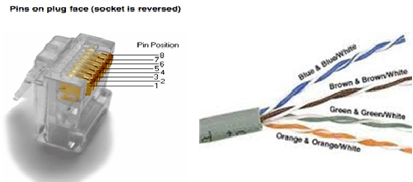
The RJ45 cable and connections should be selected so that each of the differential signals is connected to a corresponding twisted pair. Also, 5V power and ground should be connected so that they use a twisted pair and therefore keep the capacitive coupling through the cabling.
The figure below shows the RJ45 pin assignment, as well as the twisted pair cable coloring found in traditional CAT5 cables.
Software Design
Show your software design. For example, if you are designing an MP3 Player, show the tasks that you are using, and what they are doing at a high level. Do not show the details of the code. For example, do not show exact code, but you may show psuedocode and fragments of code. Keep in mind that you are showing DESIGN of your software, not the inner workings of it.
Implementation
This section includes implementation, but again, not the details, just the high level. For example, you can list the steps it takes to communicate over a sensor, or the steps needed to write a page of memory onto SPI Flash. You can include sub-sections for each of your component implementation.
Testing & Technical Challenges
Describe the challenges of your project. What advise would you give yourself or someone else if your project can be started from scratch again? Make a smooth transition to testing section and described what it took to test your project.
Include sub-sections that list out a problem and solution, such as:
My Issue #1
Discuss the issue and resolution.
Conclusion
Conclude your project here. You can recap your testing and problems. You should address the "so what" part here to indicate what you ultimately learnt from this project. How has this project increased your knowledge?
Project Video
Upload a video of your project and post the link here.
Project Source Code
References
Acknowledgement
Any acknowledgement that you may wish to provide can be included here.
References Used
List any references used in project.
Appendix
- CAN Transceiver File:S15 244 Grp9 TJA1050.pdf
- I2C Differential Buffer File:S15 244 Grp9 PCA9615.pdf
- Laser Distance Sensor File:S15 244 Grp9 Laser.pdf


