Difference between revisions of "F24: Tilt Maze"
Proj user4 (talk | contribs) (→MP3 Decoder) |
Proj user4 (talk | contribs) (→Accelerometer) |
||
| Line 376: | Line 376: | ||
|- | |- | ||
|} | |} | ||
| + | |||
| + | <td> | ||
| + | [[File:Accelerometer.jpg|200px|thumb|left|LED Matrix Front]] | ||
| + | </td> | ||
| + | <td> | ||
| + | </td> | ||
| + | </tr> | ||
| + | </table> | ||
| + | </center> | ||
===MP3 Decoder=== | ===MP3 Decoder=== | ||
Revision as of 23:30, 22 December 2024
Contents
Abstract
Tilt Maze is a motion-controlled puzzle game that challenges players to navigate a luminous ball through procedurally generated mazes using device tilting mechanics. Players must reach the exit within time constraints while maneuvering around obstacles and collecting power-ups that provide temporary advantages. The game combines physical device control with strategic gameplay elements, offering high replayability through its randomized level design and emphasizing skills in balance, spatial reasoning, and quick decision-making.
Objectives & Introduction
The Tilt Maze Game combines hardware and software to create an interactive puzzle experience. It uses an ADXL345 accelerometer for tilt-based movement control, navigating a character through a maze displayed on a 64x64 LED matrix. FreeRTOS manages concurrent tasks like accelerometer input, display updates, and game logic, ensuring smooth and responsive gameplay. Game states, collision detection, and immersive audio feedback via an MP3 decoder enhance the experience. Semaphores and mutexes ensure thread-safe resource management, while debug outputs provide insights during development. This project demonstrates advanced integration of peripherals and real-time systems in a cohesive gaming application.
TEAM MEMBERS AND RESPONSIBILITIES
- Shreya Belide
- Developed code for MP3 Decoder Driver to play background music and sound effects.
- Designed and implemented Game Architecture and State Machine logic.
- Developed collision detection logic to ensure smooth player interactions.
- Bug fixes in MP3 integration with FreeRTOS tasks.
- Integrated subsystems including audio, display, and game logic.
- Code Cleanup and Optimization.
- Game Packaging and Presentation Preparation.
- Jyoshna Mallineni
- Developed Accelerometer Driver for tilt-based control.
- Designed Maze Layouts and Game Graphics.
- Implemented logic for dynamic player movement and boundary restrictions.
- Developed and tested display rendering functions for the LED Matrix.
- Debugged issues with accelerometer sensitivity and movement logic.
- Assisted in subsystem integration and game logic testing.
- Code Cleanup and Documentation.
- Pavan Charith Devarapalli
- Developed LED Matrix Driver for rendering the game visuals.
- Implemented multi-level gameplay logic and player progression.
- Designed logic for traps and goal conditions in the maze.
- Integrated MP3 Decoder with SPI communication for audio playback.
- Debugged synchronization issues between subsystems.
- Tested and verified power supply stability for all components.
- Assisted with subsystem integration and final game testing.
- Managed Git Repository and Final Report Preparation.
Schedule
| Week# | Start Date | End Date | Task | Status |
|---|---|---|---|---|
| 1 |
|
|
|
|
| 2 |
|
|
|
|
| 3 |
|
|
|
|
| 4 |
|
|
|
|
| 5 |
|
|
|
|
| 6 |
|
|
|
|
| 7 |
|
|
|
|
| 8 |
|
|
|
|
| 9 |
|
|
|
|
| 10 |
|
|
|
|
BILL OF MATERIALS
| Part | # | Cost | Source |
|---|---|---|---|
| SJ2 Board | 1 | $50.00 | Preet |
| Sparkfun RGB (64x64) LED Matrix Display | 1 | $32.72 | Amazon |
| Accelerometer | 1 | $10.99 | Amazon |
| 12v DC Power Jack Adapter Connector | 1 | $8.90 | Amazon |
| MP3 Decoder | 1 | 6.90 | Amazon |
| Packaging | 1 | $12 | Target |
| Jumper Wires | 1 | $6.99 | Amazon |
| Total Cost | $128.5 |
Design & Implementation
The design section can go over your hardware and software design. Organize this section using sub-sections that go over your design and implementation.
Hardware Design
Discuss your hardware design here. Show detailed schematics, and the interface here.
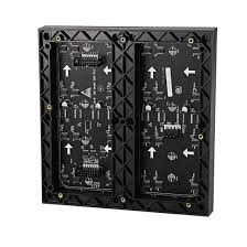
RGB LED MATRIX
It is composed of two upper and lower sectional LED pannels. Each pannel has R, G, B led channels and A, B, C, and D row control registers. Addtionally, column shift is controlled by Latch bit, clock is controled by CLK, and OE turns LED off when switching rows.
|
Connectivity Table LED Matrix to Sj2 Board:
|
Accelerometer
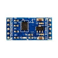
The ADXL345 accelerometer plays a central role in detecting tilt and translating it into game interactions. Here's a detailed breakdown of its purpose and usage: Tilt Detection: The ADXL345 measures acceleration along the X, Y, and Z axes, allowing you to detect the orientation and movement of the system. Game Control: The tilt input can serve as a controller for your tilt maze game. By tilting the device, you can move an object (like a ball) on the LED matrix to navigate the maze.
|
Connectivity Table LED Matrix to Sj2 Board:
|
MP3 Decoder
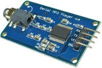
The MP3 decoder model Hiletgo GD3300 adds audio functionality, such as background music or sound effects for tilt maze game. Here's a concise explanation of its role and how to integrate it:
Background Music: Play ambient or thematic music to enhance the gaming experience. Sound Effects: Trigger sounds (e.g., collision, level-up, or maze completion) based on game events.
|
Connectivity Table MP3 Decoder to Sj2 Board:
|
</center>
Hardware Interface
- **LED Matrix Display**: 13 GPIO channels on SJ2 microcontroller
- **Accelerometer (ADXL345)**: I2C communication on SJ2 microcontroller (SCL, SDA)
- **MP3 Decoder**: SPI communication using MOSI, CS, SCK on SJ2 microcontroller
- **Speaker**: AUX cord for audio output
- **Power Supply**: 5V/4A adapter for powering the LED matrix and SJ2 microcontroller
Software Design
- **LED Matrix:
- 1. Initialized LED matrix connected pins to board IOs.
- 2. Designed matrix driver for screen display by rendering maze patterns and player movements.
- **Accelerometer**:
- 1. Initialized I2C communication for ADXL345 accelerometer.
- 2. Configured accelerometer in measurement mode and set sensitivity to ±2g.
- 3. Processed tilt data to calculate real-time player movement commands.
- **Mp3 Player**:
- 1. Initialized using UART2.
- 2. Set the device to the selected SD card and configured volume level.
- 3. Played background music and sound effects based on game state.
Implementation
- **LED Matrix Driver Functions**:
- LED Matrix:
- 1. Initialized LED matrix connected pins to board IOs.
- 2. Designed matrix driver for screen display by reading an matrix.
- 3. Designed pause menu, main menu and gameplay environment for different states of game.
- 4. Used GPIO pins as buttons as controls in main menu
- **Accelerometer Driver**:
- 1. accelerometer_init: Configures the ADXL345 accelerometer with ±2g sensitivity and sets up I2C communication with semaphores for thread safety
- 2. accelerometer_task: Periodically reads acceleration data, applies smoothing, and updates player position based on tilt movements
// Add acceleration smoothing static int16_t last_x = 0; static int16_t last_y = 0; const float smoothing_factor = 0.7f; // Increased for better responsiveness
void accelerometer_init(void) {
 // Initialize I2C at 400kHz for faster response
 i2c__initialize(I2C__2, 400 * 1000, 96 * 1000 * 1000UL, &binary_sem_memory, &mutex_memory);
 // Create mutex for thread-safe movement
 movement_mutex = xSemaphoreCreateMutexStatic(&mutex_memory);
 // Configure ADXL345 accelerometer
 i2c__write_single(I2C__2, ADXL345_WRITE, REG_DATA_FORMAT, 0x00); // ±2g range
 i2c__write_single(I2C__2, ADXL345_WRITE, REG_POWER_CTL, 0x08);   // Measurement mode
 // Initialize smoothing variables
 last_x = 0;
 last_y = 0;
}
- Maze Logic:
- 1. `get_maze_layout`: Retrieves the maze pattern for the current level
- 2. `is_wall_at`: Checks if a specific position in the maze contains a wall, used to constrain player movement
- 3. `is_goal_at`: Determines if the player has reached the maze's goal position to proceed to the next level
- **Game Logic**:
- 1. set_player_to_start : Resets the player position to the starting point of the current level
- 2. handle_collisions: Detects collisions with walls, traps, and goals, triggering state changes like `GAME_STATE_GAME_OVER` or GAME_STATE_LEVEL_UP
- 3. change_game_state: Manages game states such as `GAME_STATE_TITLE`, `GAME_STATE_PLAYING`, and `GAME_STATE_WIN`, and handles music transitions
switch (new_state) {
 case GAME_STATE_TITLE:
   stop_gameplay_music();
   mp3_decoder__play_song_at_index(SOUND_TITLE);
   enable_movement(false);
   break;
 case GAME_STATE_PLAYING:
   start_gameplay_music();
   enable_movement(true);
   break;
 case GAME_STATE_LEVEL_UP:
   stop_gameplay_music();
   mp3_decoder__play_song_at_index(SOUND_LEVELUP);
   enable_movement(false);
   break;
 case GAME_STATE_GAME_OVER:
   stop_gameplay_music();
   mp3_decoder__play_song_at_index(SOUND_LOSE);
   enable_movement(false);
   break;
 case GAME_STATE_WIN:
   stop_gameplay_music();
   mp3_decoder__play_song_at_index(SOUND_WIN);
   enable_movement(false);
   break;
 }
}
- **MP3 Decoder**:
- 1. mp3_decoder__init: Initializes the MP3 decoder, sets the default volume, and selects the storage device
- 2. mp3_decoder__play_song_at_index: Plays a specific song based on its index in single-cycle mode
- 3. mp3_decoder__play_song_with_mode: Allows playback in loop or single-cycle mode, depending on the game state
- 4. mp3_decoder__stop_playback: Stops any active song playback
- 5. mp3_decoder__volume_set_level: Adjusts the volume level of the MP3 decoder
typedef enum {
 mp3_decoder__next_song = 0x01,
 mp3_decoder__prev_song = 0x02,
 mp3_decoder__play_at_index = 0x03,
 mp3_decoder__play_loop = 0x08, // Added loop command
 mp3_decoder__set_volume = 0x06,
 mp3_decoder__select_device = 0x09,
 mp3_decoder__reset = 0x0C,
 mp3_decoder__stop = 0x16, // Added stop command
} mp3_decoder__commands_e;
// Added playback mode enum typedef enum { MP3_PLAY_ONCE, MP3_PLAY_LOOP } mp3_playback_mode_t;
Testing & Technical Challenges
The most challenging part of the Tilt Maze game was the integration and calibration of the accelerometer. Reading accurate tilt data and translating it into smooth, responsive movements for the game character required careful implementation. Additionally, ensuring the player's movement was constrained within the maze boundaries while avoiding unintended behavior added complexity.
Bug/Issue Name
| Bug Number | Description | Solution |
|---|---|---|
|
|
|
|
|
|
|
|
|
|
|
|
Conclusion
Building the Tilt Maze game on a microcontroller proved to be a rewarding and challenging experience. Developing custom drivers for the accelerometer, LED matrix, and MP3 decoder required a deep understanding of embedded systems. Implementing FreeRTOS tasks to handle concurrent updates for accelerometer input, game logic, and display rendering added complexity but ensured smooth and responsive gameplay. One of the most challenging aspects was achieving accurate and stable accelerometer readings for tilt detection, which required calibration, noise filtering, and careful logic for player movement.
Throughout the project, we encountered various issues, including synchronization conflicts, noisy sensor data, and priority balancing in FreeRTOS. These challenges taught us the importance of debugging, modular design, and leveraging RTOS APIs effectively. As embedded engineers, we learned that creating a system from scratch involves meticulous attention to both hardware and software integration.
In the end, we successfully implemented a fun and interactive game that showcases the power of embedded systems. Future improvements could include adding a scoring system, dynamic maze generation, and more refined accelerometer controls to further enhance gameplay.
Project Video
[Watch the Tilt Maze game demo]
Project Source Code
https://gitlab.com/first892736/tilt-maze-group-2
References
Acknowledgement
Special thanks to Mr. Preet Kang for his lessons and detailed-documentation website on microcontrollers.
References Used
- 1. Mp3 user manual: https://usermanual.wiki/Pdf/Serial20MP320Player20v10120Manual.2117229468/view
- 2. LPC40xx_FreeRtos Github: https://gitlab.com/sjtwo-c-dev/sjtwo-c
Appendix
- 1. LPC40xx_FreeRtos Github: https://gitlab.com/sjtwo-c-dev/sjtwo-c
- 2. FreeRTOS: https://www.freertos.org/a00116.html


