Difference between revisions of "F24: Rival Rush"
Proj user3 (talk | contribs) |
Proj user3 (talk | contribs) (→) |
||
| Line 473: | Line 473: | ||
=== <Bug/issue name> === | === <Bug/issue name> === | ||
| + | |||
===Issues, Challenges and solutions to get past them=== | ===Issues, Challenges and solutions to get past them=== | ||
'''1. RGB LED Matrix Display driver''' | '''1. RGB LED Matrix Display driver''' | ||
Revision as of 22:28, 19 December 2024
Contents
Project Title
Rival Rush
Abstract
This is a 2 player game that would be implemented on a 64*64 RGB LED. Each player has to move against the oncoming traffic without being hit by any of the vehicles. The players can move left or right horizontally across the highway by tilting the player consoles (SJ2 boards). The movement across the road by tilting is sensed by an accelerometer. The players will have 3 lives each of which is deducted per hit. The players can also collect coins on the road which add to their score. The number and speed of the approaching traffic will increase over time. The player with a greater score at the end of 60 seconds will win the game. The LED will display the players’ scores, number of lives left and the racing track on either side.
Objectives & Introduction
Show list of your objectives. This section includes the high level details of your project. You can write about the various sensors or peripherals you used to get your project completed.
Team Members & Responsibilities
- Alshama Mony Sheena
- Harshwardhan Ashish Bhangale
- Gautam Santhanu Thampy
Schedule
| Week# | Date | Task | Status |
|---|---|---|---|
| 1 | 10/14 |
|
|
| 2 | 10/21 |
|
|
| 3 | 10/28 |
|
|
| 4 | 11/04 |
|
|
| 5 | 11/11 |
|
|
| 6 | 11/18 |
|
|
| 7 | 11/25 | ||
| 8 | 12/02 |
|
|
| 9 | 12/09 |
|
|
| 10 | 12/16 |
|
|
| 11 | 05/13 |
|
|
| 12 | 05/20 |
|
Parts List & Cost
Give a simple list of the cost of your project broken down by components. Do not write long stories here.
Design & Implementation
LED Matrix Driver and Implementation
RGB LED Display Matrix Module
For the User Interface, a 64x64 LED Display Matrix has been used in this project. It has 5 address lines an
Other specifications of 64x64 RGB LED Matrix are as follows:
- Brightness: 2800cd/square meter
- Size: 160x160mm
- Pitch: 2.5M
- 5 Addressable Pins
- Scan: 1/32
- Refresh Frequency: >=400HZ
- Waterproof Class: IP43
- Weight: 204.8g (only matrix panel).
Hardware Design
SJOne board GPIO pins output 3.3V. However, to drive the RGB LED Display Matrix we need 5V. So, 3.3V from the SJOne Board is converted to 5V using 2 level shifters as shown in the pin connection diagram below:
LED Matrix Control
Hardware Interface
The RGB LED Display Matrix gets the input from Master Module (SJOne board). It is driven by the GPIO Pins of the Master Module. However, these GPIO pins are not connected directly to the display matrix since 64x64 RGB LED Matrix drives on 5V input whereas the GPIO pins from SJOne board output 3.3V. So, two level shifter ICs are used as an intermediate connection to convert 3.3V GPIO output from SJOne board to 5V before giving it as an input to the RGB Led Matrix.
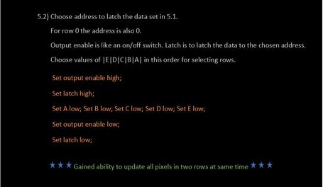
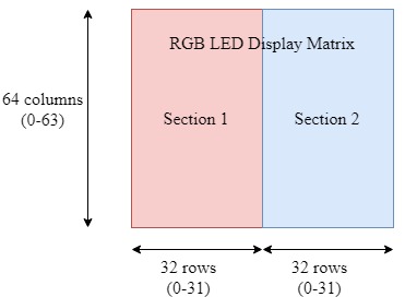
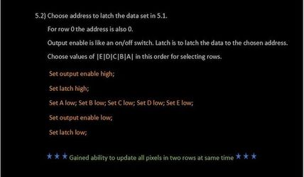
This 64x64 LED matrix has 5 address lines viz. A, B, C, D, E. With 5 address lines, we get 2^5 = 32 unique addresses. But, the matrix has 64 rows. The scan rate of the LED Matrix is 1/32, i.e., 2/64. This indicates that by making each address line high, two rows will be driven at the same time.
The LED display Matrix is divided into two sections-
- Section 1 - First 32 rows (Row 0 to row 31)
- Section 2 - Remaining 32 rows (Row 32 to row 63)
6 data lines, 3 for each section are available to drive the RGB matrix.
- R1, G1, B1 - For section 1
- R2, G2, B2 - For section 2
Other pins:
- OE - Output Enable
- Lat - Latch
- Clk - clock signal
- Vcc - High Voltage (5V)
- Gnd - Ground (0V)
Software Design
Entire driver function for RGB LED Matrix APIs was self-written from scratch.
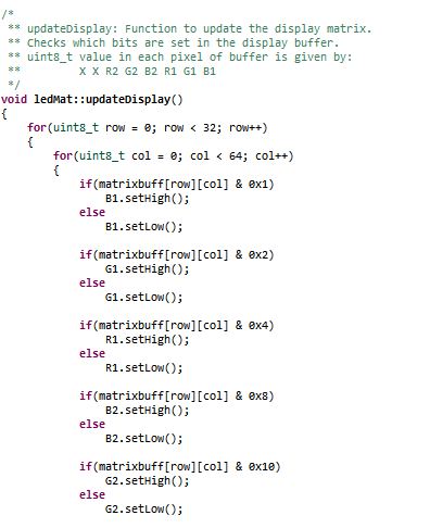
Logic: In order to save the memory, a buffer of size 32x64 used instead of using 64x64 buffer and updated every 1ms. This buffer stores the pixel values of the RGB LED matrix and updates them every 1ms. A variable of 8-bits is stored in each cell, where the first two MSB bits are not used and the remaining 6-bits represent 6 RGB data lines as: (X X R2 G2 B2 R1 G1 B1).
 uint8_t matrixbuff[MATRIX_NROWS][MATRIX_HEIGHT];                       where, MATRIX_NROWS  = 32
                                                                               MATRIX_HEIGHT = 64
                                                                               uint8_t pixel_value-> X X R2 G2 B2 R1 G1 B1
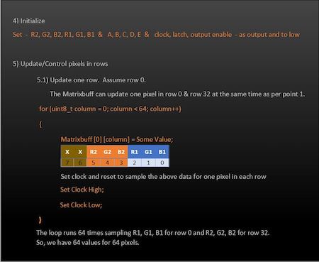
In order to drive only one row, particular address lines can be made high and enabling the RGB pins for the section in which that row lies. For example, to glow the first row (row 0) red, ABCDE = 00001 and R1 = 1. All other RGB pins should be made 0.
With the combination of address lines and 6 RGB pins, any particular row with a specific color can be displayed.
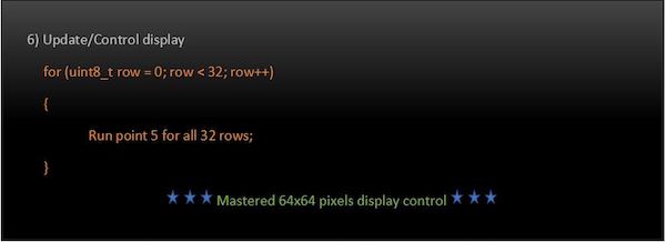
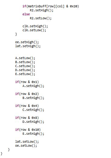
In order to update a single LED pixel value, set the variable (X X R2 G2 B2 R1 G1 B1) conditions to update the matrix buffer, and then set the clock high and low (to indicate one clock pulse). Repeat this process for as many columns present in the matrix. After this, set the output enable and latch pins high. Now, set the address lines depending upon the values set in the row number. After doing this, set the latch and output enable pins low. And then repeat this process for as many times as the number of rows (in our case, the row number is 64 but, since the matrix buffer is selected as 32 to save memory by dividing into two sections, it will be 32). In this way the pixel values are set high or low and stored in the buffer. The updateBuffer() function is called every 1ms to update the LED matrix display.
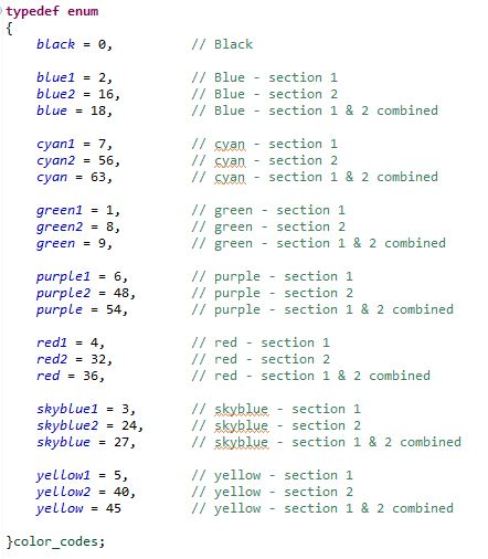
Depending upon the different values that can be stored in each cell value, an enum is used to represent different color values as shown in the below image. This helps the Master module to directly pass any color value from the enum in order to display a specific color and in a specific section of the LED Matrix Display. For example: If the Master wants to display the car for Player 1 (Player 1 is represented by red color and is in section 1) starting from position (24, 2), then it just has to call the display API function as follows:
drawCar(24, 2, red1); Note: red1 = 4 (00000100) -> R1 is set.
Similarly, if the Master wants to display the car for Player 2 (Player 2 is represented by blue color and is in section 2) at (55, 2), then it can be displayed by calling the same function
 drawCar(24, 2, red2);                       Note: red2 indicates that we want to display in Section 2.
                                                          red2 = 32 -> (00100000) -> R2 is set.
                                                          x = 55 in the display corresponds to x=24 for section 2.
To display red cars at the specified location on both the sections at the same time,
drawCar(24, 2, red); Note: red = 36 (00100100) -> R1 & R2 are set.
Also, each pixel values can be updated using drawPixel() or clearPixel() functions.
Functions like moving the display down to get real-time game feel (making sure that score displayed on the top remains intact) was a challenging task but, not impossible. It was carried out by updating the matrix updating the pixel value by copying the value above it and doing this for each pixel in a column and subsequently for all the rows to cover the entire matrix.
matrixbuff[x][y] = matrixbuff[x][y+1];
The play area above 53rd column (col=52) was uncahnged as it was reserved to display the scores. The topmost pixel value to be moved down in this application was the 53rd pixel in each row. It was cleared and all other pixel values below it were moved down. However, challenging part was to generate dotted lane marking lines at every interval while moving the display down. In the rows corresponding to these lane markings (x=10 and x=21), pixels were cleared for count equal to 4 and 5 and they were set otherwise and count made to zero after count = 5. Thus, this gave us dotted lane lines (2 pixels cleared after every 3 pixels set) at rows 11 and 22 while moving the display down.
Implementation
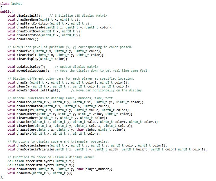
Various functions were written to display pixels, lines (dotted or solid), digits, numbers, time, text, cars, obstacles as well as to clear them. Also, APIs to check if the player hit the obstacle or no and to display the starting condition and winner of the game were written. These APIs are called by the Master module to carry out specific tasks and check conditions depending upon the values obtained from the player module. Below diagram shows the functions in the display matrix API
MP3 Decoder and Amplifier
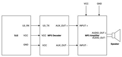
The HiLetgo YX5300 UART Control Serial MP3 Music Player Module is a kind of simple MP3 player device which is based on a high-quality MP3 audio chip. It can support 8k Hz ~ 48k Hz sampling frequency MP3 and WAV file formats. There is a TF card socket on board, so you can plug the micro SD card that stores audio files. MCU can control the MP3 playback state by sending commands to the module via UART port, such as switch songs, change the volume and play mode and so on. You can also debug the module via USB to UART module. The MP3 decoder is connected to the SJ2 board using the UART2 pins and needs 3.3V power supply and Ground pin. It works on 9600 bps baud rate. The songs are loaded into the memory card using the .wav format. Since we could not find a proper documentation for the mp3 decoder we referred to Catalex MP3 decoder document. The MP3 decoder works by sending a 8bytes of Hex command. The initial command is to select the device and later hex command are sent based upon the selection. Some of the operations that could be performed by sending the hex commands include, start a song, pause a song, increase/ decrease volume , change to next/ previous song and so on. The initial testing of the songs and the MP3 decoder are done by using a serial terminal coolterm. Hex commands are send as strings using the serial command to test and understand the mp3 decoder.
Since we wanted to use compact speakers which can be fixed inside the package and did not require an external power source we used magnetic diaphragm speakers. But this speakers when hooked to the output of the mp3 decoder produced a really low levels of audio. In order to increase the output audio levels we used Super Mini PAM8403 DC 5V 2 Channel USB Digital Audio Amplifier Board Module. The output of the mp3 decoder was connected to this amplifier and then the speakers were connected to Audio out terminals of the amplifier. The on board potentiometer of the audio amplifier can be used to increased the output audio level.
Hardware Design
Discuss your hardware design here. Show detailed schematics, and the interface here.
Hardware Interface
In this section, you can describe how your hardware communicates, such as which BUSes used. You can discuss your driver implementation here, such that the Software Design section is isolated to talk about high level workings rather than inner working of your project.
Software Design
MP3 Player Task: The task sends commands to the MP3 decoder to play a specific song. Based on the current state of the game, the Game task sends different signals to the MP3 player task. The MP3 player task plays specific songs based on the signal received.
Code Snippet
void mp3_player_task(void *pvParameters) {
  send_mp3_command(mp3_player_init, MP3_COMMAND_SIZE);
  uint8_t current_state = NO_SOUND;

  while (true) {
    if (xSemaphoreTake(countdown, 0)) {
      play_audio(COUNTDOWN);
      current_state = COUNTDOWN;
    } else if (xSemaphoreTake(crash, 0) && current_state != CRASH) {
      play_audio(CRASH);
      current_state = CRASH;
    } else if (xSemaphoreTake(car_moving, 0) && current_state != CAR) {
      play_audio(CAR);
      current_state = CAR;
    } else if (xSemaphoreTake(no_sound, 0) && current_state != NO_SOUND) {
      play_audio(NO_SOUND);
      current_state = NO_SOUND;
    } else if (xSemaphoreTake(level, 0) && current_state != LEVEL_CHANGE) {
      play_audio(LEVEL_CHANGE);
      current_state = LEVEL_CHANGE;
    } else if (xSemaphoreTake(play, 0) && current_state != PLAY) {
      play_audio(PLAY);
      current_state = PLAY;
    }

    vTaskDelay(100);
  }
}
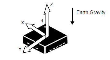
Accelerometer Task: We used on-board accelerometer to get the values. We have used only the Y-axis values to trigger movement of the player's car. We have divided the Y-axis values into different buckets which defines where the player car should move.
Code Snippet
static void accelerometer_task(void *params) {

  acceleration__axis_data_s acc_sensor_values;
  uint32_t y = 0;
  while (1) {
    acc_sensor_values = acceleration__get_data();
    y = acc_sensor_values.y;

    switch (y) {
    case 0 ... 150: //Staright
      break;

    case 151 ... 800: //Right
      move_car_right();
      break;

    case 3100 ... 3944: //Left
      move_car_left();
      break;

    case 3945 ... 4095: //Straight
      break;

    default:
      break;
    }
    vTaskDelay(50);
  }
}
Game Task: The game task generates random obstacles, check for collisions. It sends signals to the MP3 player task to play sounds as per the game state.
Random Obstacle Generator and Movement
For every level, we have new obstacles in addition to the old ones. We have an array of obstacle types and we select specific obstacles based on the level. We are using rand() to select the X-axis coordinate and to select the type of obstacle to generate.
Code Snippet
static void generate_obstacle(bitmap_object *obstacle) {
  uint8_t x, index;

  obstacle->y = BORDER_HEIGHT - CAR_HEIGHT_WITH_PADDING;

  x = rand() % LED_MATRIX_WIDTH;
  if (x < BORDER_WIDTH) {
    x = BORDER_WIDTH;
  } else if (x > (LED_MATRIX_WIDTH - BORDER_WIDTH - CAR_WIDTH_WITH_PADDING)) {
    x = LED_MATRIX_WIDTH - BORDER_WIDTH - CAR_WIDTH_WITH_PADDING;
  }
  obstacle->x = x;

  index = rand() % levels[current_level - 1].level_obstacle_mod;

  obstacle->image = obstacle_types[index].image;
  obstacle->isAlive = true;
  obstacle->color = obstacle_types[index].color;
  obstacle->movement_type = obstacle_types[index].movement_type;
  obstacle->height = obstacle_types[index].height;
  obstacle->width = obstacle_types[index].width;
  obstacle->speed = obstacle_types[index].speed;
  obstacle->counter = 0;
  obstacle->direction = index % 2;
}
Every object has padding above it and on the left and right. When we move the obstacle down by one row, the padding clears the last row. For every obstacle there are three attributes speed, life and movement type. We update the position of the obstacle when the counter reaches the corresponding speed. We have two movement types DOWN and DOWN_AND_LEFT_RIGHT. We update the counter every 30ms. So if the speed of the car is 20, then the car moves down every 30*20 = 600ms. In case of DOWN_AND_LEFT_RIGHT, we update the X-axis as well as Y-axis values. The alive attribute is set to false once the obstacle is out of the screen.
Code Snippet
static void move_obstacles(bitmap_object *obstacle) {
  obstacle->counter++;
  if (obstacle->counter < obstacle->speed) {
    return;
  }

  switch (obstacle->movement_type) {
  case DOWN:
    obstacle->y = obstacle->y - 1;
    break;
  case DOWN_AND_LEFT_RIGHT:
    obstacle->y = obstacle->y - 1;
    if (obstacle->direction == RIGHT) {
      if (obstacle->x <
          (LED_MATRIX_WIDTH - BORDER_WIDTH - CAR_WIDTH_WITH_PADDING)) {
        obstacle->x = obstacle->x + 1;
      } else {
        obstacle->direction = LEFT;
      }
    } else {
      if (obstacle->x > BORDER_WIDTH) {
        obstacle->x = obstacle->x - 1;
      } else {
        obstacle->direction = RIGHT;
      }
    }
  }

  if (obstacle->y == (-1) * CAR_HEIGHT_WITH_PADDING) {
    obstacle->isAlive = false;
    num_of_on_screen_obstacles--;
  }
}

void move() {
  for (uint8_t i = 0; i < NUM_OF_OBSTACLES; i++) {
    if (car_obstacle[i].isAlive) {
      move_obstacles(&car_obstacle[i]);
    }
  }
}
Implementation
The 64x64 LED matrix we used were from Adafruit and had a pitch of 3mm. It features 64 rows and 64 columns of LEDs, with each LED capable of emitting RGB colors. The matrix is typically interfaced through a series of GPIO pins that control the rows and columns, which are used to manage the pixels. The main interfacing include GPIO pins that control the RGB colors for each row, along with additional pins for clock, latch, and output. These connections allow for dynamic addressing of individual LEDs, which can be controlled to display images, text, or animations. The matrix usually operates using a multiplexing technique where each row is updated in sequence, creating the appearance of a continuous display. Proper timing and control of these pins are essential for achieving smooth, flicker-free visual output.
Testing & Technical Challenges
Describe the challenges of your project. What advise would you give yourself or someone else if your project can be started from scratch again? Make a smooth transition to testing section and described what it took to test your project.
Include sub-sections that list out a problem and solution, such as:
<Bug/issue name>
Issues, Challenges and solutions to get past them
1. RGB LED Matrix Display driver
We first started by porting Adafruit’s LED driver for Arduino, however we could not get it running. So we started to implement our own driver. It worked well for the bottom half of the matrix but not the top half. We debugged the code, later to realize that the SJ2 board pins which we were using for R1, G1 and B1 were not working properly. We used other GPIO pins and it solved the issue.
2. MP3 Decoder The HiLetgo YX5300 UART Control Serial MP3 Music Player Module does not have a detailed datasheet available for reference. After much researching on the internet we found a catalex_mp3 decoder data sheet which was really helpful in understanding and using the mp3 decoder.
3. Low level Audio Sound As we wanted to make the game package very compact, we opted for low power magnetic speaker which consumes less power and does not require an external power source. But when we started using this speakers we noticed that audio level was very low. We used an audio amplifier which takes in the output of the mp3 decoder and amplifies and sends it to the speaker. The onboard potentiometer on this amplifier can be used to adjust the level of the output volume.
4. Pause Bug When we paused the game, the display was frozen but after hitting the play button, the position of the car was way off when we paused. We realized that our accelerometer kept updating the position of the car, it was just not displayed. To solve this issue we now update the values only in the GAME PLAY state.
5. LED Flickering Bug Initially we were refreshing the screen by turning off all pixels and repainting the screen. As a result, at lower speeds the LED used to flicker. To solve this issue, we do not turn off all the pixels, instead we use padding above and on the left, right. Hence, after moving the object, the padding clears the unwanted row.
Conclusion
Conclude your project here. You can recap your testing and problems. You should address the "so what" part here to indicate what you ultimately learnt from this project. How has this project increased your knowledge?
Project Video
Upload a video of your project and post the link here.
Project Source Code
References
Acknowledgement
Any acknowledgement that you may wish to provide can be included here.
References Used
List any references used in project.
Appendix
You can list the references you used.


