Difference between revisions of "F24: Rival Rush"
Proj user3 (talk | contribs) |
Proj user3 (talk | contribs) |
||
| Line 251: | Line 251: | ||
Since we wanted to use compact speakers which can be fixed inside the package and did not require an external power source we used magnetic diaphragm speakers. But this speakers when hooked to the output of the mp3 decoder produced a really low levels of audio. In order to increase the output audio levels we used Super Mini PAM8403 DC 5V 2 Channel USB Digital Audio Amplifier Board Module. The output of the mp3 decoder was connected to this amplifier and then the speakers were connected to Audio out terminals of the amplifier. The on board potentiometer of the audio amplifier can be used to increased the output audio level. | Since we wanted to use compact speakers which can be fixed inside the package and did not require an external power source we used magnetic diaphragm speakers. But this speakers when hooked to the output of the mp3 decoder produced a really low levels of audio. In order to increase the output audio levels we used Super Mini PAM8403 DC 5V 2 Channel USB Digital Audio Amplifier Board Module. The output of the mp3 decoder was connected to this amplifier and then the speakers were connected to Audio out terminals of the amplifier. The on board potentiometer of the audio amplifier can be used to increased the output audio level. | ||
| − | |||
| − | |||
| − | |||
| − | |||
| − | |||
| − | |||
| − | |||
| − | |||
| − | |||
| − | |||
| − | |||
| − | |||
| − | |||
<BR/> | <BR/> | ||
Revision as of 21:12, 19 December 2024
Contents
Project Title
Rival Rush
Abstract
This is a 2 player game that would be implemented on a 64*64 RGB LED. Each player has to move against the oncoming traffic without being hit by any of the vehicles. The players can move left or right horizontally across the highway by tilting the player consoles (SJ2 boards). The movement across the road by tilting is sensed by an accelerometer. The players will have 3 lives each of which is deducted per hit. The players can also collect coins on the road which add to their score. The number and speed of the approaching traffic will increase over time. The player with a greater score at the end of 60 seconds will win the game. The LED will display the players’ scores, number of lives left and the racing track on either side.
Objectives & Introduction
Show list of your objectives. This section includes the high level details of your project. You can write about the various sensors or peripherals you used to get your project completed.
Team Members & Responsibilities
- Alshama Mony Sheena
- Harshwardhan Ashish Bhangale
- Gautam Santhanu Thampy
Schedule
| Week# | Date | Task | Status |
|---|---|---|---|
| 1 | 10/14 |
|
|
| 2 | 10/21 |
|
|
| 3 | 10/28 |
|
|
| 4 | 11/04 |
|
|
| 5 | 11/11 |
|
|
| 6 | 11/18 |
|
|
| 7 | 11/25 | ||
| 8 | 12/02 |
|
|
| 9 | 12/09 |
|
|
| 10 | 12/16 |
|
|
| 11 | 05/13 |
|
|
| 12 | 05/20 |
|
Parts List & Cost
Give a simple list of the cost of your project broken down by components. Do not write long stories here.
Design & Implementation
Display Module
LED Matrix
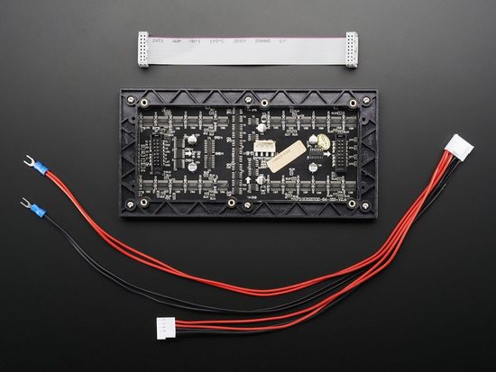
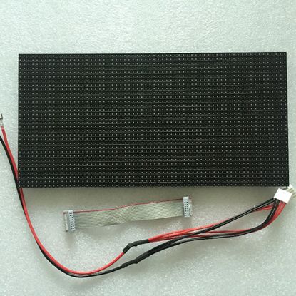
The hardware design employs the use of 64x32 RGB LED matrix panel which is the most important part of the project, this uses four data lines namely A, B, C and D which can be addressed and used to control each LED which has following technical specifications:
Dimensions:
- 110.1 x 5 x 0.2 inches
Operation Power
- AC100-240V 50-60HZ Switch-able
- 5V regulated power input, 4A max (all LEDs on)
- 5V data logic level input
- 4mm pitch
- Module Refresh: 1560hz
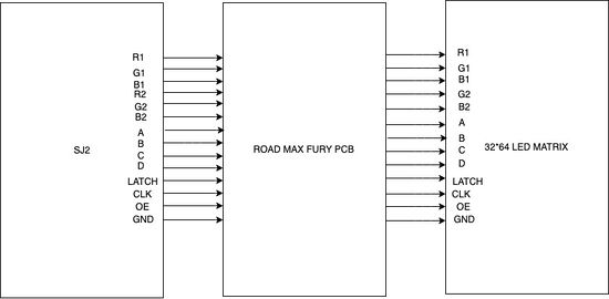
Pin Mapping:
| SJ One Board Pin | Name | Description |
|---|---|---|
| P1_14 | R1 | Top half red data |
| P4_29 | G1 | Top half green data |
| P0_7 | B1 | Top half blue data |
| P4_28 | R2 | Bottom half red data |
| P0_6 | G2 | Bottom half green data |
| P0_8 | B2 | Bottom half blue data |
| P0_26 | addrA | Address Input A |
| P1_31 | addrB | Address Input B |
| P1_20 | addrC | Address Input C |
| P1_28 | addrD | Address Input D |
| P2_0 | Clock | Shift clock |
| P2_2 | Latch | Shift in row data/Active High |
| P2_5 | Output Enable | Turn on selected rows/Active Low |
LED Matrix Driver and Implementation
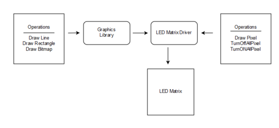
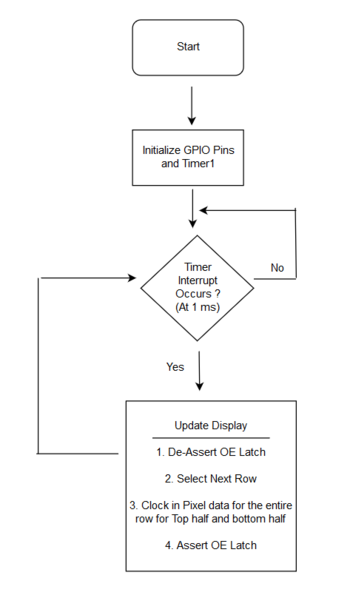
The Led Matrix Driver Library is responsible for driving individual pixels of the LED Matrix. We started understanding the functioning of the LED Matrix by reading the SparkFun's article and Adafruit's article. The Drivers provided by Adafruit uses a BCM technique (In-place of PWM) for obtaining different color combination. However when we designed our own driver we did not used the BCM technique thus were able to display only eight colors (BLACK = 0, BLUE = 1, GREEN = 2, CYAN = 3, RED = 4, MAGENTA = 5, YELLOW = 6, WHITE = 7). The software design flow is illustrated below:
Another function 'bool led_matrix__drawPixel(int16_t x, int16_t y, uint16_t color)' is used to update a pixel in Led Matrix Buffer. The 'led_matrix__drawPixel' function is used by all functions of the graphics library to update the Led Matrix Buffer.
MP3 Decoder and Amplifier
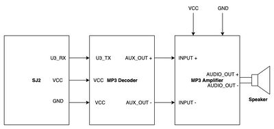
The HiLetgo YX5300 UART Control Serial MP3 Music Player Module is a kind of simple MP3 player device which is based on a high-quality MP3 audio chip. It can support 8k Hz ~ 48k Hz sampling frequency MP3 and WAV file formats. There is a TF card socket on board, so you can plug the micro SD card that stores audio files. MCU can control the MP3 playback state by sending commands to the module via UART port, such as switch songs, change the volume and play mode and so on. You can also debug the module via USB to UART module. The MP3 decoder is connected to the SJ2 board using the UART2 pins and needs 3.3V power supply and Ground pin. It works on 9600 bps baud rate. The songs are loaded into the memory card using the .wav format. Since we could not find a proper documentation for the mp3 decoder we referred to Catalex MP3 decoder document. The MP3 decoder works by sending a 8bytes of Hex command. The initial command is to select the device and later hex command are sent based upon the selection. Some of the operations that could be performed by sending the hex commands include, start a song, pause a song, increase/ decrease volume , change to next/ previous song and so on. The initial testing of the songs and the MP3 decoder are done by using a serial terminal coolterm. Hex commands are send as strings using the serial command to test and understand the mp3 decoder.
Since we wanted to use compact speakers which can be fixed inside the package and did not require an external power source we used magnetic diaphragm speakers. But this speakers when hooked to the output of the mp3 decoder produced a really low levels of audio. In order to increase the output audio levels we used Super Mini PAM8403 DC 5V 2 Channel USB Digital Audio Amplifier Board Module. The output of the mp3 decoder was connected to this amplifier and then the speakers were connected to Audio out terminals of the amplifier. The on board potentiometer of the audio amplifier can be used to increased the output audio level.
Hardware Design
Discuss your hardware design here. Show detailed schematics, and the interface here.
Hardware Interface
In this section, you can describe how your hardware communicates, such as which BUSes used. You can discuss your driver implementation here, such that the Software Design section is isolated to talk about high level workings rather than inner working of your project.
Software Design
Show your software design. For example, if you are designing an MP3 Player, show the tasks that you are using, and what they are doing at a high level. Do not show the details of the code. For example, do not show exact code, but you may show psuedocode and fragments of code. Keep in mind that you are showing DESIGN of your software, not the inner workings of it.
Implementation
This section includes implementation, but again, not the details, just the high level. For example, you can list the steps it takes to communicate over a sensor, or the steps needed to write a page of memory onto SPI Flash. You can include sub-sections for each of your component implementation.
Testing & Technical Challenges
Describe the challenges of your project. What advise would you give yourself or someone else if your project can be started from scratch again? Make a smooth transition to testing section and described what it took to test your project.
Include sub-sections that list out a problem and solution, such as:
<Bug/issue name>
Discuss the issue and resolution.
Conclusion
Conclude your project here. You can recap your testing and problems. You should address the "so what" part here to indicate what you ultimately learnt from this project. How has this project increased your knowledge?
Project Video
Upload a video of your project and post the link here.
Project Source Code
References
Acknowledgement
Any acknowledgement that you may wish to provide can be included here.
References Used
List any references used in project.
Appendix
You can list the references you used.
