Difference between revisions of "F22: Thunder Flash"
(→Schedule) |
(→Design & Implementation) |
||
| Line 479: | Line 479: | ||
</li> | </li> | ||
</ul></div> | </ul></div> | ||
| + | |||
| + | == '''MP3 Decoder''' == | ||
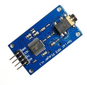
| + | This module is a straightforward MP3 player that runs on the YX5300 high-quality MP3 audio chip. MP3 and WAV file formats with sampling rates of 8 kHz to 48 kHz are supported. The micro SD card used to store the audio files can be inserted because there is a TF card socket on the board. By sending commands to the module via the UART interface, the MCU can control the MP3 playback state by altering the volume, switching tracks, etc. | ||
| + | [[File:MP3_Decoder_board.JPG|300px|thumb|center|Serial MP3 Player]] | ||
| + | |||
| + | ==== Hardware Design ==== | ||
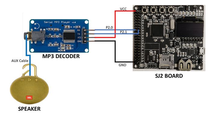
| + | The UART Tx, UART Rx, VCC, and GND pins are the 4 pins that the MP3 decoder module needs. The SJ2 board provided the module with the 3.3V it needed to start up. On the SJ2 board, UART1 pins have been set up so that commands can be sent to the decoder. This UART communication's baud rate is set at 9600 bps. Additionally, this decoder has a speaker-connected 3.5mm audio jack. | ||
| + | [[File:MP3_Decoder_SJ2_Connection.JPG|700px|thumb|center|Connection diagram of MP3 decoder to SJ2 board.]] | ||
| + | |||
| + | ==== Software Design ==== | ||
| + | |||
| + | [[File:MP3_Initialization.png|700px|thumb|center|MP3 Initialization]] | ||
| + | |||
| + | |||
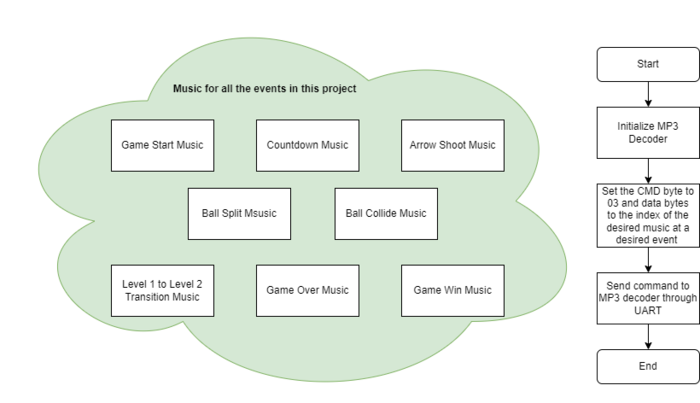
| + | In our Bow and Arrow project, the command we use plays the song by navigating to its index on the SD card. In our code, the function that sends this command is referred to as play music at index. We must first send the command [Select device] before we can send the instruction to play music at a specific index. The datasheet specifies that you should send "7E FF 06 09 00 00 02 EF" since Serial MP3 Player only accepts micro SD cards. Additionally, the function uart polled put on UART1 is being used to transmit the commands. | ||
| + | |||
| + | [[File:MP3_Flowchart.png|700px|thumb|center|MP3 Flowchart]] | ||
| + | |||
| + | |||
| + | |||
| + | |||
| + | |||
| + | |||
== '''Testing & Technical Challenges''' == | == '''Testing & Technical Challenges''' == | ||
Revision as of 21:48, 7 December 2022
Contents
Grading Criteria
- How well is Software & Hardware Design described?
- How well can this report be used to reproduce this project?
- Code Quality
- Overall Report Quality:
- Software Block Diagrams
- Hardware Block Diagrams
- Schematic Quality
- Quality of technical challenges and solutions adopted.
Bow and Arrow
Abstract
Bow and arrow is a fun, aiming archery game. Our goal is to produce a similar version of ‘Bow and Arrow’ where the archer aims the arrow at the targets (balloons) using the bow. The game would have different levels and the archer would get 3 lives to score maximum points. As the level increases the challenges and speed of the game increase. In the later levels, there would be monsters coming onto the archer. In the later levels, there would be monsters coming onto the archer, and the archer should make sure he dodges those obstacles to save his life and hit the balloons to earn points. This is all displayed on the LED matrix acting as the screen.
Objectives & Introduction
The main objective of this project was to create the “Bow and Arrow” video game displayed on a 64X64 RGB LED matrix, with one SJ2 board as a graphics processor/matrix controller, and another SJ2 board as a controller. Other objectives are the following:
- Design custom PCBs for both the gamepad and matrix controller SJ2 boards.
- Use the FreeRTOS Real-Time Operating System on both SJ2 boards.
- Establish UART communications through Xbee between the two SJ-Two Microcontrollers.
- Create simple coding logic for displaying required characters and game objects.
- Add background music to the game to enhance the gameplay experience.
Team Members & Technical Responsibilities
- Shreya Kulkarni
- Integrating of Graphics Driver
- Game logic design
- Joystick and button Implementation
- Pinky Mathew
- Interfacing of LED Matrix and driver design
- Game logic design and implementation
- Graphics driver design and implementation
- Joystick Integration
- Pushkar Deodhar
- Zigbee module
- Integrating MP3 module with the Game
- Hardware Designing & PCB Integration
- Noel Smith
- MP3 Audio Encoder/Decoder
- Integrating MP3 player with the Game
- Hardware Designing & PCB Integration
Administrative Responsibilities
| Administrative Roles | ||||
|---|---|---|---|---|
|
Noel Smith | |||
|
Pinky Mathew | |||
|
Shreya Kulkarni | |||
|
Pushkar Deodhar | |||
Schedule
| Week# | Start Date | End Date | Task | Status |
|---|---|---|---|---|
| 1 |
|
|
|
|
| 2 |
|
|
|
|
| 3 |
|
|
|
|
| 4 |
|
|
|
|
| 5 |
|
|
|
|
| 6 |
|
|
|
|
| 7 |
|
|
|
|
| 8 |
|
|
|
|
| 9 |
|
|
|
|
| 10 |
|
|
|
|
Bill Of Materials
| Item# | Part Description | Part Model & Vendor | Quantity | Cost |
|---|---|---|---|---|
| 1 | Microcontroller Boards | SJ2 Boards (Purchased from Preet Kang) | 2 | $100.00 |
| 2 | LED Matrix Display | Adafruit RGB LED Matrix Panel - 64x64 | 1 | $87.95 |
| 3 | PCB | JLC PCB | 5 | $18.00 |
| 4 | Electronics Fun Kit & Power Supply Module | ELEGOO Upgraded Electronics Fun Kit | 2 | $7.56 |
| 5 | MP3 Decoder | HiLetgo YX5300 UART Control Serial MP3 Music Player Module | 1 | $6.99 |
| 6 | Power Adapter for LED Matrix | Belker 36W Adapter | 1 | $15.00 |
| 7 | XBee Module | XBee 2mW Wire Antenna - Series 2C (ZigBee Mesh) | 2 | $62.00 |
| 8 | Joystick | HiLetgo Game Joystick Sensor Game Controller | 1 | $4.89 |
| 9 | Push Button Switch | Anchor Electronics | 1 | $1.00 |
| 10 | Jumper Cables | Anchor Electronics | 1 | $7.00 |
| 11 | Female headers for SJ2-PCB Connection | Anchor Electronics | 1 | $2.50 |
| 12 | Ribbon Cable Connector for LED Matrix-PCB Connection | Anchor Electronics | 1 | $1.00 |
| 13 | Soldering Wire & 18 Gauge Wire | Anchor Electronics | 1 | $3.00 |
| 14 | Copper Board for Game Controller Connections | Anchor Electronics | 1 | $4.00 |
| Total Cost | 22 | $317.89 |
Design & Implementation
PIN CONFIGURATION
-
Pin# SJ2 Main Board - LED Matrix Pin Configuration SJ-2 PIN R1 PIN for Red terminal of RGB LED for the upper half of LED Matrix P0_0 G1 PIN for Green terminal of RGB LED for the upper half of LED Matrix P0_1 B1 PIN for Blue terminal of RGB LED for the upper half of LED Matrix P2_2 R2 PIN for Red terminal of RGB LED for the lower half of LED Matrix P2_4 G2 PIN for Green terminal of RGB LED for the lower half of LED Matrix P2_5 B2 PIN for Blue terminal of RGB LED for the lower half of LED Matrix P2_6 A Mux pin for row selection P2_7 B Mux pin for row selection P2_8 C Mux pin for row selection P2_9 D Mux pin for row selection P0_16 E Mux pin for row selection P0_15 OE Output Enable P1_28 LATCH Data Latch P1_29 CLK Clock Signal P0_17 MP3 Decoder RX UART Receive From MP3 Decoder P2_1 TX UART Send Command from SJ-2 Main Board P2_0 XBEE Module Receiver RX UART Receive From Game Controller P0_11 VCC VCC Supply VCC 3.3 -
Pin# Controller Board Pin Configuration uC PIN XBEE Module Transmitter TX UART Transmit to Main Board P0_10 VCC VCC Supply VCC 3.3 Joystick VCC VCC 3.3V GND GND GND Vx X-axis ADC Reading for character movement P0_25 Push Button I/0 Pin Arrow Shooting P1_29
MP3 Decoder
This module is a straightforward MP3 player that runs on the YX5300 high-quality MP3 audio chip. MP3 and WAV file formats with sampling rates of 8 kHz to 48 kHz are supported. The micro SD card used to store the audio files can be inserted because there is a TF card socket on the board. By sending commands to the module via the UART interface, the MCU can control the MP3 playback state by altering the volume, switching tracks, etc.
Hardware Design
The UART Tx, UART Rx, VCC, and GND pins are the 4 pins that the MP3 decoder module needs. The SJ2 board provided the module with the 3.3V it needed to start up. On the SJ2 board, UART1 pins have been set up so that commands can be sent to the decoder. This UART communication's baud rate is set at 9600 bps. Additionally, this decoder has a speaker-connected 3.5mm audio jack.
Software Design
In our Bow and Arrow project, the command we use plays the song by navigating to its index on the SD card. In our code, the function that sends this command is referred to as play music at index. We must first send the command [Select device] before we can send the instruction to play music at a specific index. The datasheet specifies that you should send "7E FF 06 09 00 00 02 EF" since Serial MP3 Player only accepts micro SD cards. Additionally, the function uart polled put on UART1 is being used to transmit the commands.
Testing & Technical Challenges
Describe the challenges of your project. What advise would you give yourself or someone else if your project can be started from scratch again? Make a smooth transition to testing section and described what it took to test your project.
Include sub-sections that list out a problem and solution, such as:
<Bug/issue name>
Discuss the issue and resolution.
Conclusion
Conclude your project here. You can recap your testing and problems. You should address the "so what" part here to indicate what you ultimately learnt from this project. How has this project increased your knowledge?
Project Video
Upload a video of your project and post the link here.
Project Source Code
- github repository link[1]
References
Acknowledgement
Any acknowledgement that you may wish to provide can be included here.
References Used
- Serial MP3 Player Datasheet
- Binary code pattern generator for LED Matrix
- Everything You Didn't Want to Know About RGB Matrix Panels
Appendix
You can list the references you used.


