Difference between revisions of "F21: ACE MARIO"
Proj user13 (talk | contribs) (→MP3 Decoder) |
Proj user13 (talk | contribs) (→Bluetooth Interface) |
||
| Line 338: | Line 338: | ||
==== Software Design ==== | ==== Software Design ==== | ||
| + | |||
| + | |||
| + | ---- | ||
=== Bluetooth Interface === | === Bluetooth Interface === | ||
Revision as of 07:20, 15 December 2021
Contents
Grading Criteria
- How well is Software & Hardware Design described?
- How well can this report be used to reproduce this project?
- Code Quality
- Overall Report Quality:
- Software Block Diagrams
- Hardware Block Diagrams
- Schematic Quality
- Quality of technical challenges and solutions adopted.
Project Title
Ace Mario
Abstract
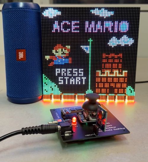
Super Mario is one of the best-selling games of all time, with more than 50 million copies sold worldwide. Our goal will be to produce a similar version of it where the player controls Mario. Mario has to race through the Mushroom Kingdom and save Princess.
Objectives & Introduction
Show list of your objectives. This section includes the high level details of your project. You can write about the various sensors or peripherals you used to get your project completed.
Team Members & Responsibilities
- Vivek Tapkir
- Shreevats Gadhikar
- Daya Modekar
Schedule
| Week# | Start Date | End Date | Task | Status |
|---|---|---|---|---|
| 1 |
|
|
|
|
| 2 |
|
|
|
|
| 3 |
|
|
|
|
| 4 |
|
|
|
|
| 5 |
|
|
|
|
| 6 |
|
|
|
|
| 7 |
|
|
|
|
| 8 |
|
|
|
|
| 9 |
|
|
|
|
Parts List & Cost
General Parts
| Item # | Part | Vendor | Qty | Cost |
|---|---|---|---|---|
| 1 | 64x64 RGB LED Matrix | Adafruit | 1 | $54.95 |
| 2 | SJ-2 Boards | SJSU | 2 | $100.00 |
| 3 | HC-05 Bluetooth Boards | Amazon | 2 | $20.00 |
| 4 | MP3 Decoder/Player Board | Amazon | 1 | $6.99 |
| 5 | Joystick | Amazon | 1 | $4.89 |
| 6 | Power Supply for LED Matrix (5V 5A) | Amazon | 1 | $15.99 |
| 7 | JBL Speakers | already had | 1 | $0 |
| 8 | Audio Jack Cable | already had | 1 | $0 |
| 9 | MicroSD Card & Adapter | already had | 1 | $0 |
| 10 | Vibration Sensor | Amazon | 1 | $10.99 |
Design & Implementation
The design section can go over your hardware and software design. Organize this section using sub-sections that go over your design and implementation.
Hardware Design
LED Matrix
MP3 Decoder
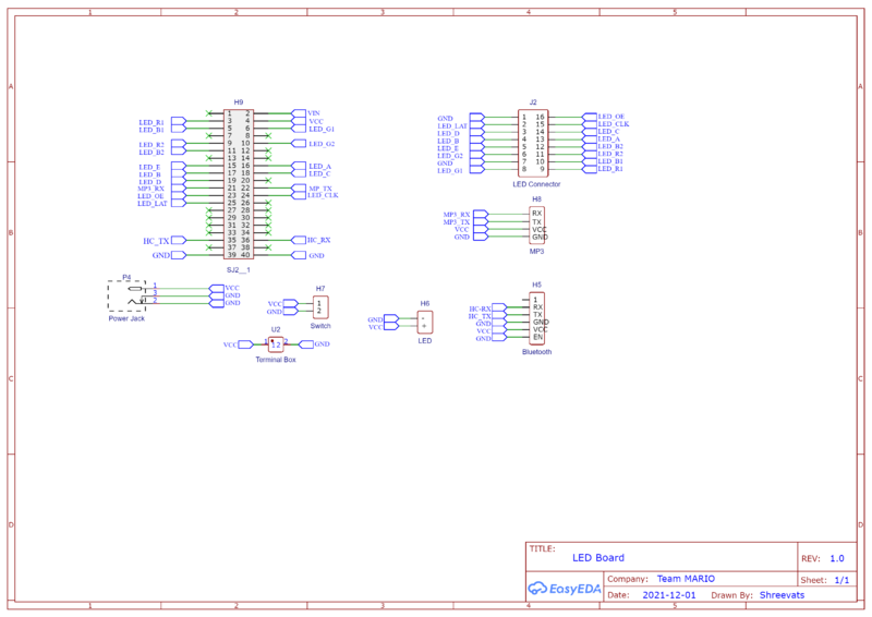
The MP3 player device which is based on a high-quality MP3 audio chip -YX5300 is used in our project to play different soundtracks based on the current state of the game such as jump, victory, game over and Mario run states. Our master controller unit (sjtwo-c board) controls MP3 playback state by sending commands to serial MP3 via UART port
Hardware Design
Software Design
Bluetooth Interface
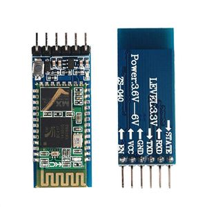
For this project, we used two HC-05 Bluetooth modules. One Bluetooth was configured on the LED matrix controller board while the other was configured on the gamepad controller. The Bluetooth configured on the led matrix controller worked as a slave, only receives commands, while the one configured on the gamepad worked as master, sending controls to the other controller. The master Bluetooth connected to the gamepad controller transmitted the joystick direction. The transmitted direction was in the form of x and y coordinates. The UP and FORWARD direction was calibrated using the x and y coordinates. So along with UP and FORWARD direction, the joystick switch button data was also transmitted using Bluetooth.
We selected the HC-05 Bluetooth module to transmit data over other modules because of their ease to configure, they are extremely reliable and also easy to set up. Both the Bluetooth modules were configured using AT commands. Using AT commands made our job easy to set one Bluetooth as a master while the other as a slave. The best thing about using AT commands is that we can change the configuration as per our needs. The UART baud rate was set to 38400.
Hardware Design
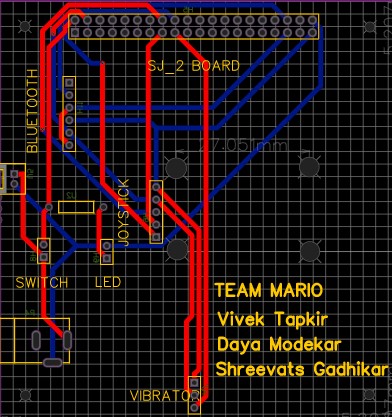
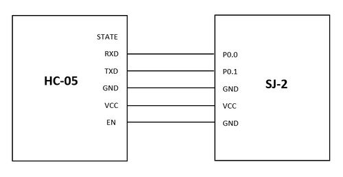
The HC-05 Bluetooth module was connected to both boards using the SJ2 pins. The pins used were P0.0 and P0.1. These Bluetooth modules communicate with each other over the UART interface. The gamepad controller board process the joystick signals to UP and FORWARD and also the button press and then sends them to the Bluetooth module via UART.
Game pad Controller
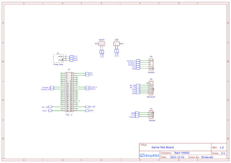
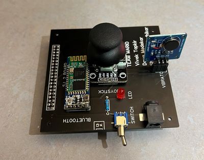
Gamepad Controller basically consists of only three main components. Firstly the joystick, which is used to get the UP and FORWARD direction, and also the press button. Second is the Bluetooth module which is used to transmit the data via UART to the other board. And lastly, the vibration sensor to produce the vibration. The vibration sensor is used to get the real game feel.
Joystick
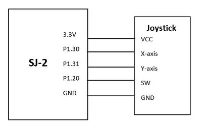
The joystick was interfaced on the Game-pad controller. We used a joystick to get a UP and FORWARD direction. The joystick was configured using ADC pins of the SJ2 board. The Joystick provides an analog output, therefore they were connected to ADC pins to get the digital values. The values of the X-axis and Y-axis varied from 0 to 4095. The center was 2048 for both X-axis and Y-axis. The UP and FORWARD direction was calculated using these ADC values. The joystick also had a digital switch. This digit switch was used as a press button in our game. These three contents (i.e UP, FORWARD, Button_press) were transmitted to the led board using Bluetooth.
Hardware Design
The hardware design was pretty simple. The two analog output pins i.e X-axis and Y-axis were connected to ADC pins of the SJ2 board. The ADC pins used were P1.30 and P1.31 to get the UP direction and the FORWARD direction. The digital switch was connected to one of the gpio pins on the SJ2 board. This gpio pin was read to detect if the switch was pressed.
Vibration Sensor
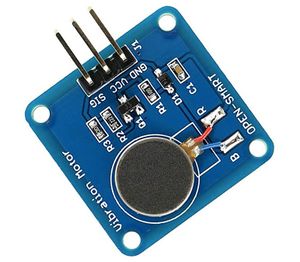
A vibration sensor was used to produce the vibration on the game-pad controller to get the real feel of the game. The vibration sensor was triggered on the Mario jump state and also when Mario died.
Hardware Design
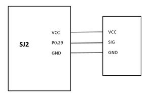
Vibration consists of just 3 pins. VCC for power, Signal pin to trigger the pin, and GND. The signal pin of the vibration sensor was connected to one of the gpio pin (P0.29) of the SJ2 board.
Testing & Technical Challenges
Describe the challenges of your project. What advise would you give yourself or someone else if your project can be started from scratch again? Make a smooth transition to testing section and described what it took to test your project.
Include sub-sections that list out a problem and solution, such as:
<Bug/issue name>
Discuss the issue and resolution.
Conclusion
Conclude your project here. You can recap your testing and problems. You should address the "so what" part here to indicate what you ultimately learnt from this project. How has this project increased your knowledge?
Project Video
Upload a video of your project and post the link here.
Project Source Code
References
Acknowledgement
Any acknowledgement that you may wish to provide can be included here.
References Used
List any references used in project.
Appendix
You can list the references you used.
