Difference between revisions of "F20: Bubble Shooter"
Proj user7 (talk | contribs) |
Proj user7 (talk | contribs) |
||
| Line 247: | Line 247: | ||
<BR/> | <BR/> | ||
| − | == '''Bill Of Materials'''== | + | == '''Bill Of Materials''' == |
{| class="wikitable" style="margin-left: 0px; margin-right: auto;" | {| class="wikitable" style="margin-left: 0px; margin-right: auto;" | ||
|- | |- | ||
| Line 411: | Line 411: | ||
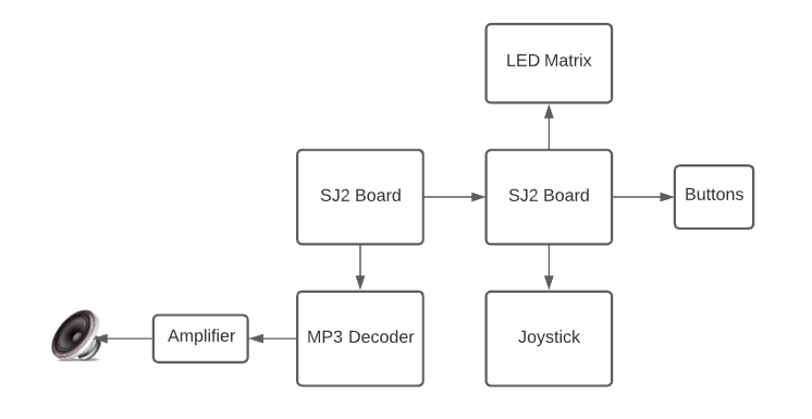
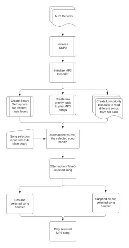
[[File:MP3 Flow Chart(1).png|700x800px|thumb|center|MP3 Layout]] | [[File:MP3 Flow Chart(1).png|700x800px|thumb|center|MP3 Layout]] | ||
| − | + | # Implementation | |
To initialize the MP3 decoder, we have first initialized the SSP0 and the SJ2 pins connected to the MP3 decoder with proper input/output function configurations. We then configure the decoder registers by selecting the MP3 chip select pin and writing data over SPI. These include the mode (default), clock frequency multiplier (3x), volume (max), and audio (44100 Hz stereo data). We then flush the mp3 decoder, sending it 2500 0 bytes. | To initialize the MP3 decoder, we have first initialized the SSP0 and the SJ2 pins connected to the MP3 decoder with proper input/output function configurations. We then configure the decoder registers by selecting the MP3 chip select pin and writing data over SPI. These include the mode (default), clock frequency multiplier (3x), volume (max), and audio (44100 Hz stereo data). We then flush the mp3 decoder, sending it 2500 0 bytes. | ||
| Line 417: | Line 417: | ||
We create a low priority task (read_song_from_sd_card) to read from the SD Card. Read_song_from_sd_card task first opens the mp3 file on the sd card and determines the size. Afterward, it reads in 512 bytes at a time to a global array (whenever the music playing task has finished playing the previous 16 bytes) and sets a global variable (sdready) to true. It will continue to do this until the file has been completely read, and then start over from the beginning. | We create a low priority task (read_song_from_sd_card) to read from the SD Card. Read_song_from_sd_card task first opens the mp3 file on the sd card and determines the size. Afterward, it reads in 512 bytes at a time to a global array (whenever the music playing task has finished playing the previous 16 bytes) and sets a global variable (sdready) to true. It will continue to do this until the file has been completely read, and then start over from the beginning. | ||
| − | + | ## Feeding the Decoder and Playing Music | |
We create another low priority task (play_song_task) to play music. If the MP3 DREQ pin is currently set, it delays. Otherwise, whenever sdready is true, it selects the Data chip select line and sends 32 bytes over the SPI bus. It then deselects data chip select and redoes this 16 times (sending the 512 bytes that have been read). After it has sent all 512 bytes, it sets sdready to false so the read_song_from_sd_card task knows to read in the next 512 bytes. It continues to repeat this process for as long as mp3sdcard reads in data to the array. | We create another low priority task (play_song_task) to play music. If the MP3 DREQ pin is currently set, it delays. Otherwise, whenever sdready is true, it selects the Data chip select line and sends 32 bytes over the SPI bus. It then deselects data chip select and redoes this 16 times (sending the 512 bytes that have been read). After it has sent all 512 bytes, it sets sdready to false so the read_song_from_sd_card task knows to read in the next 512 bytes. It continues to repeat this process for as long as mp3sdcard reads in data to the array. | ||
| − | + | ## Binary Semaphore | |
We have low priority created check_which_song_recieved_from_main_sj2_board_semaphore_give which will act as a producer task which will select which mp3 background music or sound fx need to be played and it will give the semaphore of the selected music file to the high priority consumer task called play_song_task which will suspend all other song handlers and play the selected song. | We have low priority created check_which_song_recieved_from_main_sj2_board_semaphore_give which will act as a producer task which will select which mp3 background music or sound fx need to be played and it will give the semaphore of the selected music file to the high priority consumer task called play_song_task which will suspend all other song handlers and play the selected song. | ||
| − | + | ## Communication between Main and sister SJ2 board | |
We have initialized 3 GPIO pins on the main(P0.15, P0.18, P0.1) and sister board(P2.0, P2.2, P2.5) and we have a total of 8 songs list, to which the respective GPIO pins will be high or low based on the song selection. The GPIO pins on the mainboard will be the output pins and the GPIO pins on the sister board will be the input pins. Henceforth, the sister board will receive input from the mainboard for the song selection and a binary semaphore will play the song. | We have initialized 3 GPIO pins on the main(P0.15, P0.18, P0.1) and sister board(P2.0, P2.2, P2.5) and we have a total of 8 songs list, to which the respective GPIO pins will be high or low based on the song selection. The GPIO pins on the mainboard will be the output pins and the GPIO pins on the sister board will be the input pins. Henceforth, the sister board will receive input from the mainboard for the song selection and a binary semaphore will play the song. | ||
Revision as of 04:59, 18 December 2020
Contents
Abstract
Bubble shooter is an arcade game that has bubbles or balls present on the screen. The bubbles are of different colors and the goal is to clear them by forming a group of bubbles (3 or more) of the same color. Points are earned upon clearing the bubbles and increases with the number of bubbles cleared in a single shot. The player wins upon clearing the screen and loses when the bubbles touch the bottom of the screen.
Objectives & Introduction
The objective of this project is to develop a simple, single-player 2D game using LPC 4078 microcontroller on an LED matrix display. It focuses on integrating the micro-controller peripheral drivers, led drivers, MP3 player, button and joystick controller interface and the application software in FreeRTOS. The button controller interface consists of the joystick for moving the shooter left and right. The button is used to fire the ball.
Team Members
Technical Responsibilities
|
Hisaam Hashim, Amiraj Nigam, Anirudh Ashrit, Akshat Bhutiani |
|---|---|
|
Anirudh Ashrit |
|
Hisaam Hashim |
|
Hisaam Hashim, Akshat Bhutiani |
|
Amiraj Nigam, Anirudh Ashrit |
|
Akshat Bhutiani |
|
Amiraj Nigam, Hisaam Hashim |
Administrative Responsibilities
|
Hisaam Hashim |
|---|---|
|
Akshat Bhutiani & Anirudh Ashrit |
|
Hisaam Hashim |
|
Amiraj Nigam & Anirudh Ashrit |
|
Akshat Bhutiani |
Schedule
| Week# | Start Date | End Date | Task | Status |
|---|---|---|---|---|
| 1 |
|
|
|
|
| 2 |
|
|
|
|
| 3 |
|
|
|
|
| 4 |
|
|
|
|
| 5 |
|
|
|
|
| 6 |
|
|
|
|
| 7 |
|
|
|
|
| 8 |
|
|
|
|
| 9 |
|
|
|
|
| 10 |
|
|
|
|
Bill Of Materials
| Item# | Part Description | Part Model & Vendor | Quantity | Cost |
|---|---|---|---|---|
| 1 | Microcontroller Boards | SJ2 Boards (Purchased from Preet Kang) | 1 | $50.00 |
| 2 | LED Matrix Display | RGB LED Matrix Panel - 32X64 | 1 | $55.00 |
| 3 | Audio decoder Breakout Board | MP3 PLayer Shield | 1 | $26.95 |
| 4 | Analog 2-axis Thumb Joystick | Analog 2-axis Joystick | 1 | $10.36 |
| 5 | Power Supply | 5V/3A Power Supply | 1 | $8.99 |
PCB Design
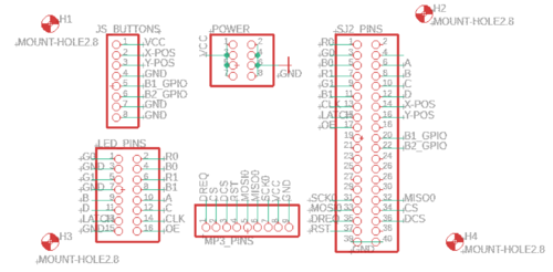
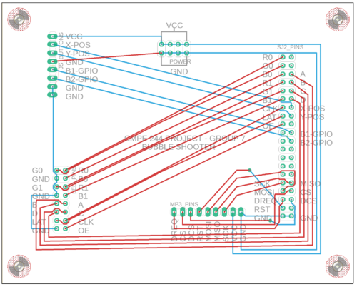
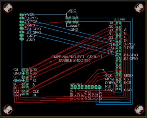
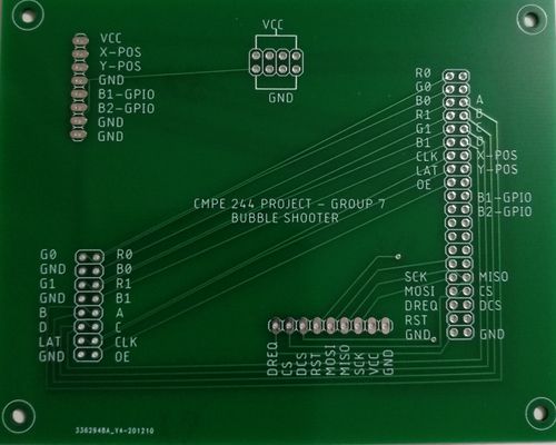
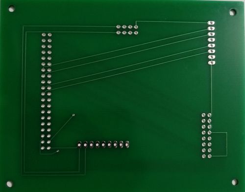
The board is designed to connect modules in the game directly. Autodesk's Eagle software is used to design the Schematics and Board layout. The board has 2 layers(Top and Bottom). JLCPCB is the manufacturer of the PCB board. Connections from SJ2 Board are provided to the PCB, which are internally connected to MP3 Decoder, Joystick, Buttons, and LED Matrix pins. These are connected directly to the peripherals using a harness. Additional power and ground pins are also provided on the board.
Joystick
Hardware Design
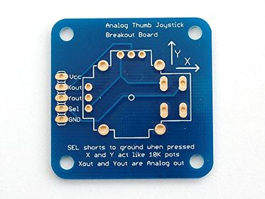
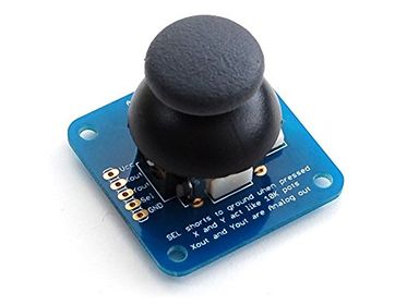
An ADA512 2-axis Analog Joystick and Button is used for controlling the movement of the launcher and shooting the ball. The data from the joystick is read using the ADC pins of the SJTwo board. The button switch is detected using a digital pin on the board.
| X values & Mapping | Y values & Mapping |
|---|---|
| 2297 (center) | 2295 (center) |
| 43 (left) | 45 (up) |
| 4095 (right) | 4090 (down) |
MP3 Decoder
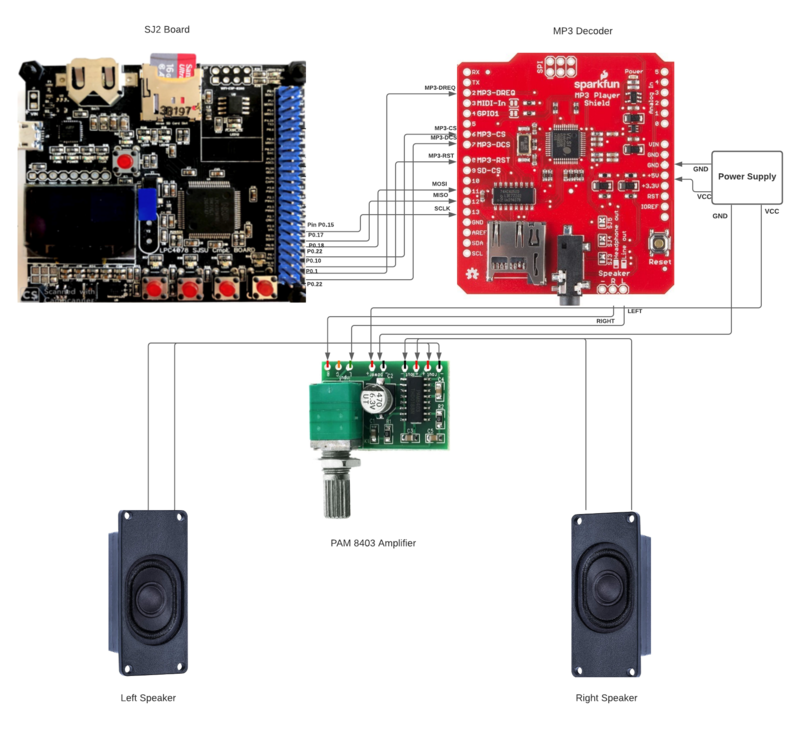
The MP3 shield communicates with the sister SJ2 board through SPI communication protocol with the SPI0 pins of the SJ2 board as follows:
| Label | Name | Function | Pin Connection | Description |
|---|---|---|---|---|
| 1 | MP3-DREQ | Decoder Data Request | Pin 0.1 | MP3 decoder signals to master to ready to receive next 32 bytes of data |
| 2 | MP3-CS | VS1053B Chip Select | Pin 0.22 | Chip select pin for MP3 decoder to be activated while sending control signals |
| 3 | MP3-DCS | VS1053B Data CS | Pin 0.0 | Data Chip Select Pin for the MP3 decoder to be activated while sending audio data signals. |
| 4 | MP3-RST | VS1053 Reset | Pin 0.10 | Reset pin for the MP3 Decoder |
| 5 | MOSI | Master Output Slave Input | Pin 0.18 | Master send data to Slave over SPI bus |
| 6 | MISO | SPI Bus (Master Input Slave Output) | Pin 0.17 | Slave send data to master over SPI bus |
| 7 | SCK | SPI Clock | Pin 0.15 | Clock generated by the master over SPI bus |
| 8 | +5V | +5V | PCB Vout | 5 Volt Input from PVB |
| 9 | GND | GND | GND | GND connected to PCB |
Hardware Design
Software Design
- Implementation
To initialize the MP3 decoder, we have first initialized the SSP0 and the SJ2 pins connected to the MP3 decoder with proper input/output function configurations. We then configure the decoder registers by selecting the MP3 chip select pin and writing data over SPI. These include the mode (default), clock frequency multiplier (3x), volume (max), and audio (44100 Hz stereo data). We then flush the mp3 decoder, sending it 2500 0 bytes. Reading the MP3 File from an SD Card[edit] We create a low priority task (read_song_from_sd_card) to read from the SD Card. Read_song_from_sd_card task first opens the mp3 file on the sd card and determines the size. Afterward, it reads in 512 bytes at a time to a global array (whenever the music playing task has finished playing the previous 16 bytes) and sets a global variable (sdready) to true. It will continue to do this until the file has been completely read, and then start over from the beginning.
- Feeding the Decoder and Playing Music
We create another low priority task (play_song_task) to play music. If the MP3 DREQ pin is currently set, it delays. Otherwise, whenever sdready is true, it selects the Data chip select line and sends 32 bytes over the SPI bus. It then deselects data chip select and redoes this 16 times (sending the 512 bytes that have been read). After it has sent all 512 bytes, it sets sdready to false so the read_song_from_sd_card task knows to read in the next 512 bytes. It continues to repeat this process for as long as mp3sdcard reads in data to the array.
- Binary Semaphore
We have low priority created check_which_song_recieved_from_main_sj2_board_semaphore_give which will act as a producer task which will select which mp3 background music or sound fx need to be played and it will give the semaphore of the selected music file to the high priority consumer task called play_song_task which will suspend all other song handlers and play the selected song.
- Communication between Main and sister SJ2 board
We have initialized 3 GPIO pins on the main(P0.15, P0.18, P0.1) and sister board(P2.0, P2.2, P2.5) and we have a total of 8 songs list, to which the respective GPIO pins will be high or low based on the song selection. The GPIO pins on the mainboard will be the output pins and the GPIO pins on the sister board will be the input pins. Henceforth, the sister board will receive input from the mainboard for the song selection and a binary semaphore will play the song.
LED Matrix Interfacing
Game
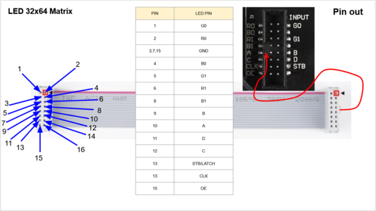
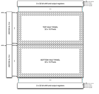
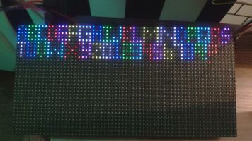
We use a 32x64 LED matrix consisting of 2048 LEDs arranged in 32 rows and 64 columns each, with each led having separate Red, Green, and Blue LED chips assembled together as a single unit. This 32x64 LED matrix is comprised of 2 of 16x32 led matrices placed vertically to each other. There are different drivers for controlling the corresponding rows and columns each. In order to illuminate a particular led, one needs to access and control the corresponding row and column (just like the coordinate-axis). To change the color of a particular led, each led must be controlled using the driver for that row and column. A layout of pins and connections can be seen below:
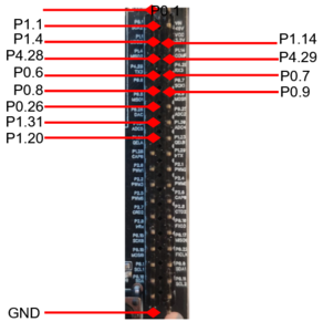
| LED Matrix Pins | Connection to SJTwo board |
|---|---|
| R0 | Pin 0.1 |
| G0 | Pin 1.1 |
| B0 | Pin 1.4 |
| R1 | Pin 4.28 |
| B1 | Pin 0.6 |
| G1 | Pin 0.8 |
| A | Pin 1.23 |
| B | Pin 1.29 |
| C | Pin 2.1 |
| D | Pin 2.4 |
| CLK | Pin 0.26 |
| STB | Pin 1.31 |
| OE | Pin 1.20 |
| GND | GND |
The matrix pixels are controlled by 6 drivers, 3 for the top half of the matrix(R0, G0, B0) and 3 for the bottom half(R1, G1, B1). The three drivers for R, G, and B share an SCLK, Latch, and OE signal. The top half pixels of the matrix controlled by R0, G0, B0 are rows 0-15, and the second half controlled by R1, G1, B1 are rows 16-31. The display is multiplexed at a duty cycle of 1/16, this means that one row in the top half and one row in the bottom half will be illuminated at a time. In order to display an image, the row and column LEDs for that image must be turned “ON”, therefore, the entire panel must be scanned at a rate(speed) at which it appears that the image is being displayed without flickering. To display different colors and different brightness levels, the LED chips of the corresponding row and column must be adjusted by varying the amount and time that each LED chip is turned on during each cycle.
LED Matrix Specifications:
5V regulated power input, 4A max (all LEDs on)
2.1 mm x 2.1 mm LED size
1/16 Scan Rate
Software Design & Implementation
Analog Joystick & Button Device Driver
The ADA512 joystick's device driver works on the principle that the ADC pins will be able to read the x and y values. The joystick consists of 2 inbuilt potentiometers that provide output (x and y directions) according to the way the joystick is moved.
Steps to read joystick data:
1. Turn on the ADC Peripheral
2. Make the ADC pin operational by setting the appropriate pin functionality using the IOCON registers.
3. Set the appropriate ADC clock (12.4 MHz is the maximum clock supported by the ADC).
4. Set the ADC pin functionality as input.
5. Select the number of channels to read.
6. Select burst mode for immediate conversion.
void adc__initialize_alien(void)
{
Turn ON ADC peripheral;
make ADC operational;
set ADC clock;
Set Pin functions;
select ADC channels;
start burst mode;
}

data get_data(adc_channel_e x_port, adc_channel_e y_port, gpio_s button_press) {
data s;
s.x_data = adc__get_adc_value(x_port);
s.y_data = adc__get_adc_value(y_port);
if (gpio__get(button_press)) {
s.switch_pressed = true;
} else {
s.switch_pressed = false;
}
return s;
}
LED Matrix Device
Game
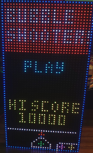
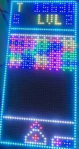
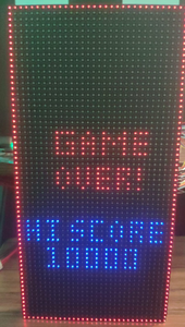
The game has 3 levels apart from the main menu, Credit scene, and Game-over screen. Just like any other arcade game, the game only starts when you earn credits and it is earned by pressing a button. The game begins with the press of another button. A block of bubbles starts falling down with every turn and finishes if it touches the danger line below. Bubbles, when hit with similar color, get destroyed and the game advances to the next level when all the bubbles on the screen are cleared. There's also a hack to traverse through levels, just press the credit score button and it will do the job for you. But hey, that's a cheat code, so you're a cheater!
RGB Color Combo
| Red | Blue | Green | Color |
|---|---|---|---|
| 0 | 0 | 0 | White |
| 0 | 0 | 1 | Blue |
| 0 | 1 | 0 | Green |
| 0 | 1 | 1 | Cyan |
| 1 | 0 | 0 | Red |
| 1 | 0 | 1 | Magenta |
| 1 | 1 | 0 | Yellow |
| 1 | 1 | 1 | Black |
Implementation
1. Initialize the LED matrix by configuring necessary pin directions.
2. Disable Output Enable (OE) GPIO before feeding matrix data.
3. Select the required row by setting bits on A, B, C, D GPIO pins.
4. Loop through the pixels (columns) in the selected row and set the pixel color on R, G, B GPIO pins.
5. Set zero on R, G, B GPIO pins to mask that particular pixel.
6. Set and Reset the clock for pushing the R, G, B bits for each column.
7. Issue latch to mark the row's completion and reset latch before going to the next row.
8. Follow steps 2 to 7 for other rows.
for (uint8_t row = 0; row < (MAX_ROW); row++) {
     disableOE();
     set_row(row);
     for (uint8_t col = 0; col < MAX_COL; col++) {
       LPC_GPIO0->PIN |= (1 << CLK);
       set_color_bottom(game_matrix[row + (MAX_ROW / 2)][col]);
       set_color_top(game_matrix[row][col]);
       LPC_GPIO0->PIN &= ~(1 << CLK);
     }
     LPC_GPIO0->PIN |= (1 << LAT);
     enableOE();
     LPC_GPIO0->PIN &= ~(1 << LAT);
     enableOE();
     vTaskDelay(1);
}
Graphics Driver
We have managed to program the graphics in a relatively simple way by looking at the ADAFruit gfx library that comes ready to use with Arduino. Our graphics driver can implement graphics and animations such as letters, numbers, ball appearance and ball disappearance etc.
void place_launcher(LedMatrixDisplay led_display, pixel_color rgb, gfx__cursor start_cursor, bool
choose_back_frame) {

game_event object_property = BACKGROUND_OBJECT;
rgb.event = object_property;
draw_line(led_display, rgb, ROTATION_90, start_cursor, 9, choose_back_frame);
modify_pixel(led_display, rgb, start_cursor.x + 0, start_cursor.y + 1, choose_back_frame);
modify_pixel(led_display, rgb, start_cursor.x + 0, start_cursor.y + 2, choose_back_frame);
modify_pixel(led_display, rgb, start_cursor.x + 1, start_cursor.y + 3, choose_back_frame);
modify_pixel(led_display, rgb, start_cursor.x + 2, start_cursor.y + 4, choose_back_frame);
modify_pixel(led_display, rgb, start_cursor.x + 3, start_cursor.y + 5, choose_back_frame);
modify_pixel(led_display, rgb, start_cursor.x + 4, start_cursor.y + 5, choose_back_frame);
modify_pixel(led_display, rgb, start_cursor.x + 5, start_cursor.y + 5, choose_back_frame);
modify_pixel(led_display, rgb, start_cursor.x + 6, start_cursor.y + 4, choose_back_frame);
modify_pixel(led_display, rgb, start_cursor.x + 7, start_cursor.y + 3, choose_back_frame);
modify_pixel(led_display, rgb, start_cursor.x + 8, start_cursor.y + 1, choose_back_frame);
modify_pixel(led_display, rgb, start_cursor.x + 8, start_cursor.y + 2, choose_back_frame);
}
Testing & Technical Challenges
Describe the challenges of your project. What advice would you give yourself or someone else if your project can be started from scratch again? Make a smooth transition to the testing section and described what it took to test your project.
Include sub-sections that list out a problem and solution, such as:
<Bug/issue name>
Discuss the issue and resolution.
Conclusion
This project was a fun and strenuous application of our engineering and project management skills.
After completing the driver labs during CMPE 244, we felt confident that we could develop a driver, for the Adafruit LED matrix, without using any third party libraries. We researched the hardware operations of the LED matrix and how to drive the RGB LED's. Once we could control LED's one at a time, the project evolved from an engineering problem into more of a creative exercise.
Overall I think the biggest lessons that we learned is project management based. We spent a lot of time choosing between various game designs and it forced us to start our final iteration later than we would have liked. However, we bonded together and worked hard and managed to get the game working.
Project Video
Upload a video of your project and post the link here.
Project Source Code
References
Acknowledgement
We would like to sincerely thank Professor Preetpal Kang for his allround guidance, feedback and support. His classroom lectures were significant in imparting knowledge on embedded systems. Further, we would like to thank the ISA team for their advice.
