Difference between revisions of "S20: Tesla Model RC"
(→Printed Circuit Board) |
(→Printed Circuit Board) |
||
| Line 497: | Line 497: | ||
== Printed Circuit Board == | == Printed Circuit Board == | ||
| − | [[File:CAN_Board.jpg|thumb|100px|middle]] | + | [[File:CAN_Board.jpg|thumb|100px|middle|center]] |
| − | [[File:Power_Board.jpg|thumb|100px|middle]] | + | [[File:Power_Board.jpg|thumb|100px|middle|center]] |
<Picture and information, including links to your PCB> | <Picture and information, including links to your PCB> | ||
Revision as of 01:17, 22 May 2020
Contents
Tesla Model RC
Abstract
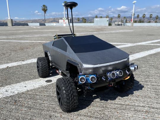
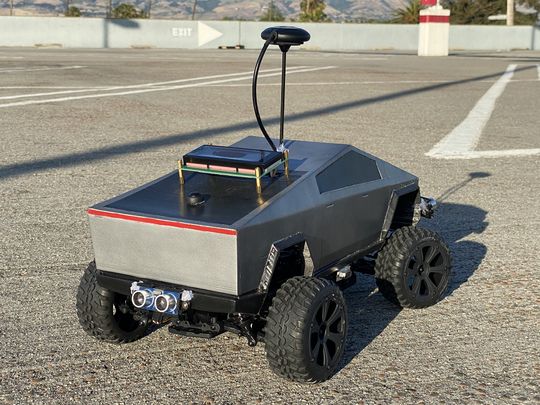
Tesla Model RC is an electric, battery-powered, self-navigating RC car. The aim is to navigate to the destination set on the Android application by utilizing GPS navigation. The car combines the data received from multiple sensors to perceive its surroundings to avoid obstacles in its path.
Introduction
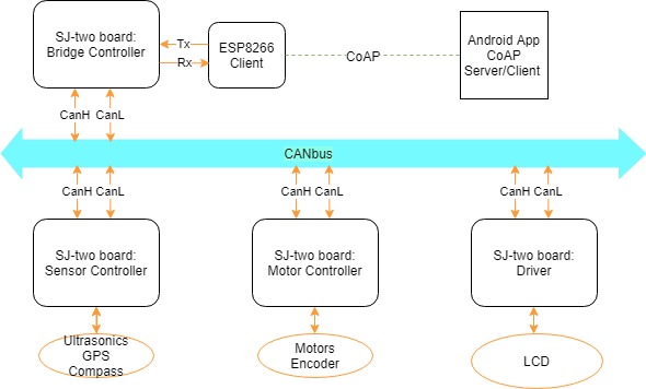
The project was divided into 5 modules:
- Bridge and Sensor Controller
- Motor Controller
- Geographical Controller
- Driver and LCD controller
- Android Application
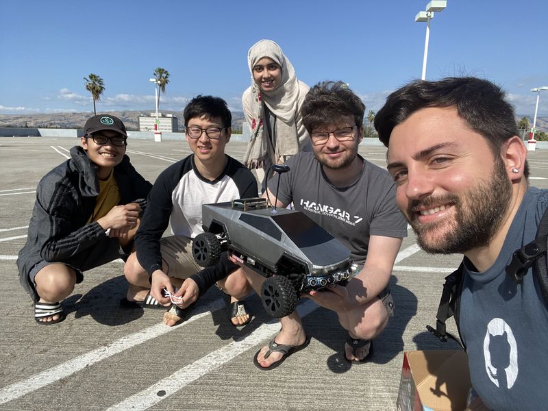
Team Members & Responsibilities
- Salvatore Nicosia Gitlab
- Motor Controller
- Geographical Controller
- System Integration and Testing
- RC Car Design: 3D Printing
<Member picture>
- Nickolas Schiffer
- Motor Controller
- Geographical Controller
- Danny Nuch Gitlab
- Bridge Sensor Controller
<Member picture here>
- Ayesha Siddiqua
- Driver & LCD Controller
<Member picture here>
- Andrew Kwon
- Android Application
- Review Team
Schedule
| Week# | Start Date | End Date | Task | Status |
|---|---|---|---|---|
| 1 |
|
|
|
|
| 2 |
|
|
|
|
| 3 |
|
|
|
|
| 4 |
|
|
|
|
| 5 |
|
|
|
|
| 6 |
|
|
|
|
| 7 |
|
|
|
|
| 8 |
|
|
|
|
| 9 |
|
|
|
|
| 10 |
|
|
|
|
| 11 |
|
|
|
|
Parts List & Cost
| Item# | Part Desciption | Vendor | Qty | Cost |
|---|---|---|---|---|
| 1 | RC Car 1/10 Scale | Redcat Racing [1] | 1 | $99.99 + Tax |
| 2 | CAN Transceivers TJA1050 | LIVISN [2] | 5 | $6.39 + Tax |
| 3 | GPS Module Built-in Compass | Readytosky [3] | 1 | $28.89 + Tax |
| 4 | HC-SR04 Ultrasonic Module | ELEGOO [4] | 5 | $9.98 + Tax |
| 5 | HC-020K Wheel Encoder Module | Hilitchi [5] | 1 | $9.99 + Tax |
| 6 | ESP8266 WiFi Module | DIYmall [6] | 1 | $6.55 + Tax |
| 7 | Extra 7.2V 5000mAh NiMH battery | Melasta [7] | 1 | $29.99 + Tax |
| 8 | Micro-USB to USB cable | Walmart [8] | 4 | $4.00 + Tax |
| 9 | EL-CP-004 120pcs Multicolored Dupont Wire | ELEGOO [9] | 1 pack | $6.98 + Tax |
| 10 | SJTwo Microcontroller | SCE at SJSU [10] | 4 | $40 |
| 11 | Black PLA Filament | Hatchbox [11] | 1 | $22.99 + Tax |
| 12 | 120 Ω Resistor | Excess Solutions | 2 | $0.30 |
| 13 | 1 MΩ Resistor | Excess Solutions | 1 | $0.15 |
| 13 | 100 kΩ Resistor | Excess Solutions | 1 | $0.15 |
| 14 | DB9 Female Connector Right Angle Mount | Excess Solutions | 1 | $0.30 |
| 15 | 2.54 Male Header Strip 36 Pin | Excess Solutions [12] | 1 | $0.36 |
| 16 | 5x7cm Prototype Board | uxcell [13] | 3 | $7.09 + Tax |
| 17 | 2.54mm JST-XHP 2 Pin Housing with 2.54mm JST XH Female Connector | QLOUNI [14] | 8 | |
| 18 | 12mm Waterproof Push Button Momentary On Off Switch | PP-NEST [15] | 1 | |
| 19 | #22 Gauge Wire | Elenco [16] | As needed | |
| 20 | LM2596 Buck Converter DC to DC | D-PLANET [17] | 1 | $5.95 + Tax |
| 21 | 11 in. x 14 in. x .093 in. Acrylic Sheet | The Home Depot [18] | 1 | $6.67 + Tax |
| 22 | 20x4 LCD Display Module | [19] | 1 | $ |
| 23 | 6-32 Brass Motherboard Standoffs | Hantof [20] | 36 | $14.58 + Tax |
| 24 | Metallic Aluminium Spray Paint | Walmart [21] | 1 | $3.96 + Tax |
| 25 | Metallic Dark Metal Spray Paint | Walmart [22] | 1 | $4.96 + Tax |
| 26 | Plastidip Black Spray Paint | Walmart [23] | 1 | $5.82 + Tax |
Printed Circuit Board
<Picture and information, including links to your PCB>
CAN Communication
<Talk about your message IDs or communication strategy, such as periodic transmission, MIA management etc.>
Hardware Design
<Show your CAN bus hardware design> High Level Hardware Diagram
DBC File
https://gitlab.com/tesla-model-rc/sjtwo-c/-/blob/dev/dbc/tesla_model_rc.dbc
Bridge Sensor ECU
https://gitlab.com/tesla-model-rc/sjtwo-c/-/tree/dev/projects/sensor
https://gitlab.com/tesla-model-rc/esp8266-coap-server
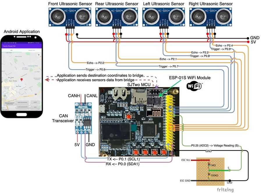
Hardware Design
| SJTwo Board | Module | Description | Protocol/Bus |
|---|---|---|---|
| P4.28 (TX3) | RX (ESP8266) | ESP8266 Rx data line | UART 3 |
| P4.29 (RX3) | TX (ESP8266) | ESP8266 Tx data line | UART 3 |
| P0.6 | Trigger (Ultrasonic) | Front sensor | |
| P2.0 | Echo (Ultrasonic) | Front sensor | |
| P0.7 | Trigger (Ultrasonic) | Rear sensor | |
| P2.1 | Echo (Ultrasonic) | Rear sensor | |
| P0.8 | Trigger (Ultrasonic) | Left sensor | |
| P2.2 | Echo (Ultrasonic) | Left sensor | |
| P0.9 | Trigger (Ultrasonic) | Right sensor | |
| P2.4 | Echo (Ultrasonic) | Right sensor | |
| P0.25 (ADC2) | Voltage reading (S) | Output of voltage divider | |
| P0.1 (SCL1) | CAN transceiver (Tx) | CAN transmit | CAN |
| P0.0 (SDA1) | CAN transceiver (Rx) | CAN receive | CAN |
| 5V (Ultrasonics) | Vcc | ||
| GND | GND | Ground |
Software Design
Bridge and Sensor Node
The Bridge and Sensor node interfaces with four ultrasonic sensors (front, back, left, and right) and the ESP8266 Wifi module for bridging connection with a mobile application to control the car and display ultrasonic ranging diagnostics.
Sensor Node and CAN Bus Periodics Handler module
The CAN bus handler has periodicially running functions specific to a task and is called in the Periodics module. Debug messages that may be enabled are sent at 1Hz. The handler of all incoming messages (including Wifi messages) is parsed in 10Hz, along with MIA management and the transmission of CAN messages. Unique to this node is the 100Hz functions that initiates and records Ultrasonic sensor rangings at this rate along with the Wifi character parser which fills the message buffer. This module wraps the Sensor Node module.
The Sensor Node module creates the sensing messages that are sent over the CAN bus. These messages include battery voltage level and all four ultrasonic ranging distances. Furthermore, the GPS longitude and latitude value and start/stop state changes parsed from Wifi transmissions are sent as well. This module handles MIA messages of the Driver node's heartbeat message. On not receiving the Driver node's heartbeat message, this module will not send messages over CAN bus and brighten LED0 indicating the node is not synchronized with the Driver node.
Wifi module
Battery Tracking module
Ultrasonics and GPIO Interrupts module
Average Buffer module
Ultrasonic smoothing by averaging
low pass filter for zeros (Ultrasonics received too quickly)
ESP8266
Bridging between ESP8266 and mobile application is done through the creation of an access point on the ESP8266. Furthermore, the ESP8266 opens a server socket through CoAP allowing other CoAP clients to transmit or receive data from a created resource (/topics). The mobile application serves as the CoAP client and currently performs:
(GET) /heartbeat will receive string: "tmrc:heartbeat"
(GET) /getRadars will receive string: "aa,bb,cc,dd" where a is front radar, b is left radar, c is right radar, and d is back radar
(PUT) /setStatus will send string - either "$stop\n" or "$start\n"
(PUT) /setCoordinates will send coordinates as string - i.e. "#Sxxx.xxxxxx,Syyy.yyyyyy\n" where S is the sign and x is latitude and y is longitude
/getRadars resource will update through UART from a microcontroller. The string must follow the format: "^%02,%02,%02,%02" where '^' is the identifier for setting this resource. This length is also fixed where each radar data must have a width of no more than 2.
/setStatus resource has an identifier of '$', while /setCoordinates resource has an identifier of '#'. Both resources require appending a new line character at the end of string. This is essential for parsing strings on microcontroller side as the ESP8266 echoes received data over UART.
Project Setup
This project is built with ESP8266 RTOS SDK for programming the ESP8266. FreeRTOS, UART, Wifi with CoAP libraries are fully utilized in this project.
See the Getting Started Guide for full steps to configure and use ESP-IDF to build projects.
Wifi Access Point module
ESP8266 opens an access point for other wireless devices to connect too. This access point follows adaptation of this example:
https://github.com/espressif/ESP8266_RTOS_SDK/tree/master/examples/wifi/getting_started/softAP.
UART Configuration module
UART is simply transmitted over UART0 TX/RX pins. This example is integrated.
CoAP Server module
CoAP server would startup a daemon task, create resources and receive data from CoAP clients and transmit data to CoAP clients. This server follows adaptation of a couple examples:
https://github.com/espressif/ESP8266_RTOS_SDK/tree/master/examples/protocols/coap_server
https://github.com/obgm/libcoap-minimal/blob/master/server.cc
https://github.com/obgm/libcoap/blob/develop/examples/coap-server.c
The Constrained Application Protocol (CoAP) is a specialized web transfer protocol for use with constrained nodes and constrained networks in the Internet of Things.
The protocol is designed for machine-to-machine (M2M) applications such as smart energy and building automation.
Please refer to RFC7252 for more details.
Technical Challenges
ultrasonic sensors smoothing/filtering
Motor ECU
https://gitlab.com/tesla-model-rc/sjtwo-c/-/tree/dev/projects/motor_node
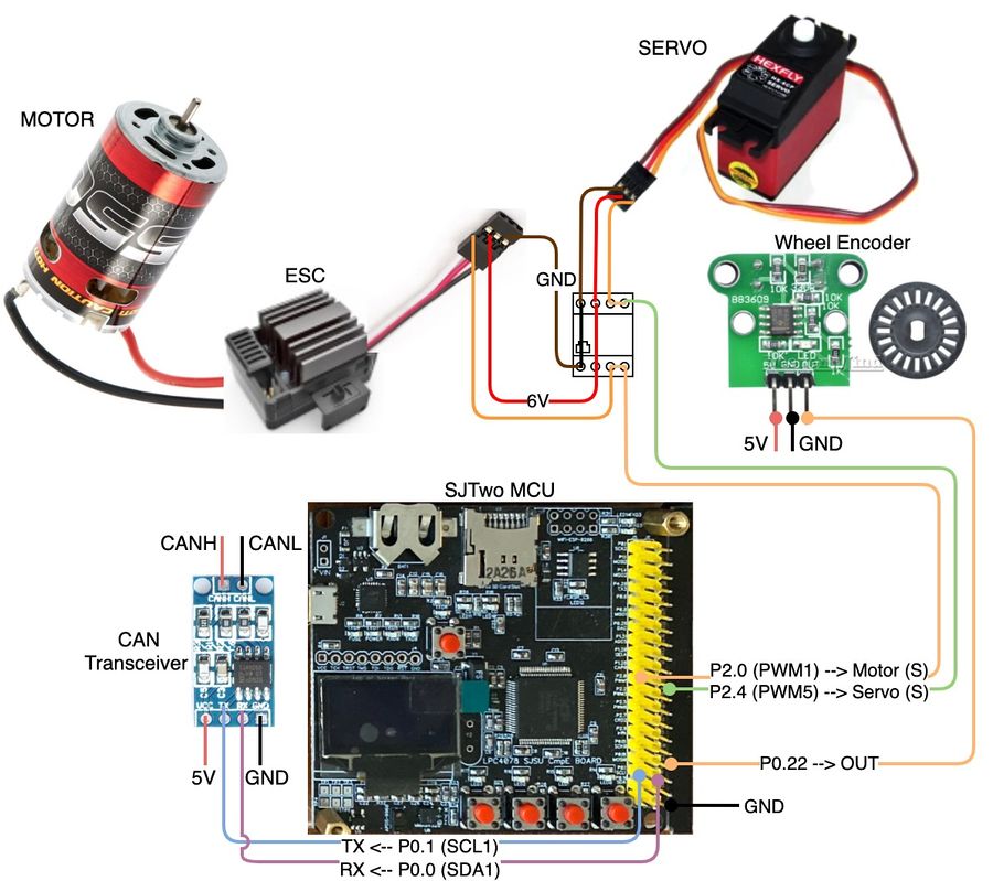
Hardware Design
| SJTwo Board | Module | Description | Protocol/Bus |
|---|---|---|---|
| P2.0 (PWM1) | Motor (S) | Control signal for motor speed | |
| P2.4 (PWM5) | Servo (S) | Control signal for servo steering | |
| P0.22 (PWM1) | Wheel encoder (Out) | Output signal of wheel encoder | |
| P0.1 (SCL1) | CAN transceiver (Tx) | CAN transmit | CAN |
| P0.0 (SDA1) | CAN transceiver (Rx) | CAN receive | CAN |
| 6V Motor and Servo | Vcc | ||
| 5V Wheel encoder | Vcc | ||
| GND | GND | Ground |
Software Design
<List the code modules that are being called periodically.>
Technical Challenges
< List of problems and their detailed resolutions>
Geographical ECU
https://gitlab.com/tesla-model-rc/sjtwo-c/-/tree/dev/projects/geo_node
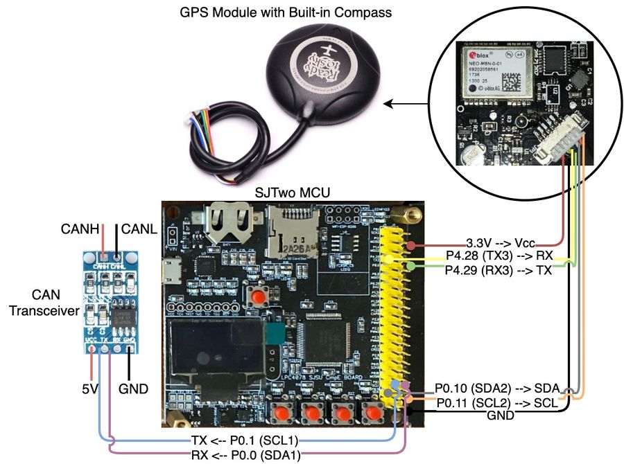
Hardware Design
| SJTwo Board | GPS/Compass Module | Description | Protocol/Bus |
|---|---|---|---|
| P4.28 (TX3) | RX (Yellow Wire) | Ublox M8N Rx data line | UART 3 |
| P4.29 (RX3) | TX (Green Wire) | Ublox M8N Tx data line | UART 3 |
| P0.10 (SDA2) | SDA (White wire) | HCM5883L SDA | I2C 2 |
| P0.10 (SCL2) | SCL (Orange wire) | HCM5883L SCL | I2C 2 |
| P0.1 (SCL1) | CAN transceiver (Tx) | CAN transmit | CAN |
| P0.0 (SDA1) | CAN transceiver (Rx) | CAN receive | CAN |
| Vcc 3.3V | Vcc (Red wire) | Vcc | |
| GND | GND (Black wire) | Ground |
Software Design
<List the code modules that are being called periodically.>
Technical Challenges
GPS (Ublox Neo-M8N)
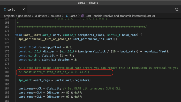
- Problem:The enabled 2-stop bits in uart.c were causing communication problems between the SJTwo MCU and the Ublox M8N GPS module.
- Solution:To solve the 2 stop bits configuration was disabled in uart.c in the uart__init() function as shown in figure # and issue was solved.
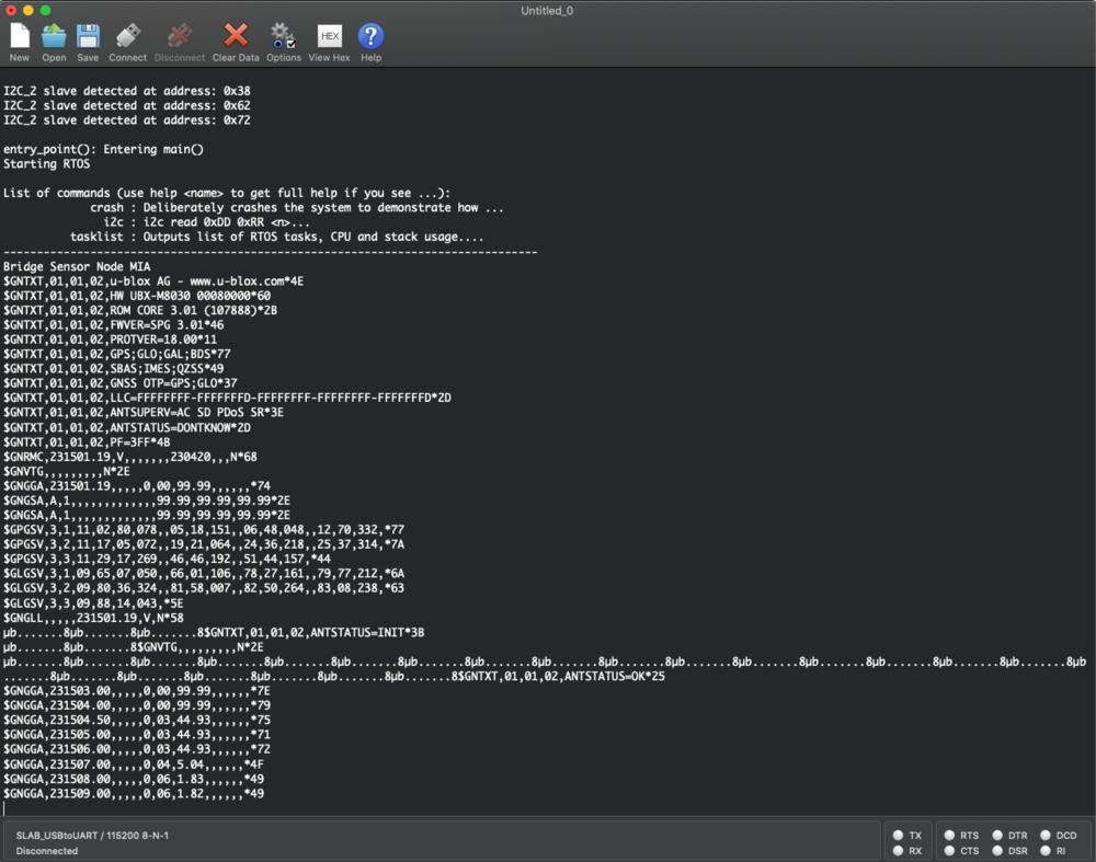
- Problem:GPS module did not retain configurations and were lost after being powered off for many hours going back back to default settings. This problem was crucial since it was causing the SJ2 to parse the latitude and longitude incorrectly from other messages other than NMEA GNGGA.
- Solution: To solve this configuration problem u-center which is an interface for the GPS Ublox module was used to read which strings the program sends over UART to configure the GPS module. This solution was implemented in the gps.c module creating a function called gps__private_configure_for_nmea_gngga() in which holds a char array with the hex representation of the configurations needed to disable all of the NMEA messages except GNGGA. This function then sends this configuration values back to the GPS module over UART and the GPS module responds back with an ACK message (8μ.......) from every configuration message meaning that the configurations were successfully applied as shown in figure #. The function gps__private_configure_for_nmea_gngga() could not be called in the periodic_callbacks__initialize() function has it required more time to properly configure the GPS. As a solution, a bool flag indicating that the configuration was done was used along with calling gps__private_configure_for_nmea_gngga() in the gps_run_once_10Hz() to allow it properly configure the GPS module.
Compass (HMC5883L 3-Axis Magnetometer)
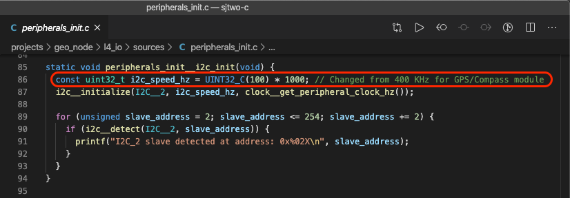
- Problem:SJTwo MCU could not detect the slave address of the HMC5883L magnetometer on the I2C Bus 2.
- Solution:Upon reading the HMC5883L datasheet it was mentioned that it works at 400KHz. However, this was not the case as changing the speed in peripherals__init.c module from 400KHz to 100KHz solved the issue and the SJTwo board successfully detected the HMC5883L 3-Axis Magnetometer. In Figure # is shown the function a long with change it was made. In addition, changing the speed did not affect the other modules using I2C Bus 2.
- Problem:Compass heading degree true north was off by about 90 degree when compared to the compass of smart phone. This problem was due the fact the compass had to be completely flat to show proper values. In addition, the default calibration seemed also to be a problem in providing an accurate heading degree a long with hard iron and soft iron interferences.
- Solution:To solve these problems a function to calibrate the compass was implemented in which calculates offset and scale correcting for hard iron and soft iron interferences respectively. The process to calibrate consisted in turning the compass at different angles to collect as many sample points as possible and store offsets values of x and y axes in const variables which were then used in the equations to compute the heading degree. Although this corrected some of the imprecision problems, not having the compass completely flat still provided results that were not precise. To solve this issue the compass was compensated for tilt by using the built-in accelerometer of the SJTwo board which provides roll and pitch and the tilt compensation algorithm described at this link. The challenge in making this work properly was that the axes of the magnetometer and the axes of the accelerometer need to be perfectly aligned. However, after finalizing the place of the compass on the RC car it was fairly easy to align the axes. The tilt compensation system for the compass is show in figure #. After including the tilt compensation algorithm the compass heading degree was off by 1-2 degrees when tilted in all directions which drastically improved the accuracy from non-compensated in which the heading was off by 60-90 degrees when the compass was not held flat.
- Problem:Compass heading degree was decreasing when turning clock-wise rather then increasing.
- Solution:To solve this problem, the Azimuth rather then being calculated as atan2(Y / X) was calculated as atan2(X / Y). This fixed the Azimuth orientation however, North degree was shown as 180 degrees which was incorrect. Finally to compensate for this, π was subtracted from the Azimuth = atan2(X / Y) - π to show the correct decimal degree for true North which is 0 degrees.
Driver Controller & LCD
https://gitlab.com/tesla-model-rc/sjtwo-c/-/tree/dev/projects/driver_controller_node
Hardware Design
| SJTwo Board | LCD Module | Description | Protocol/Bus |
|---|---|---|---|
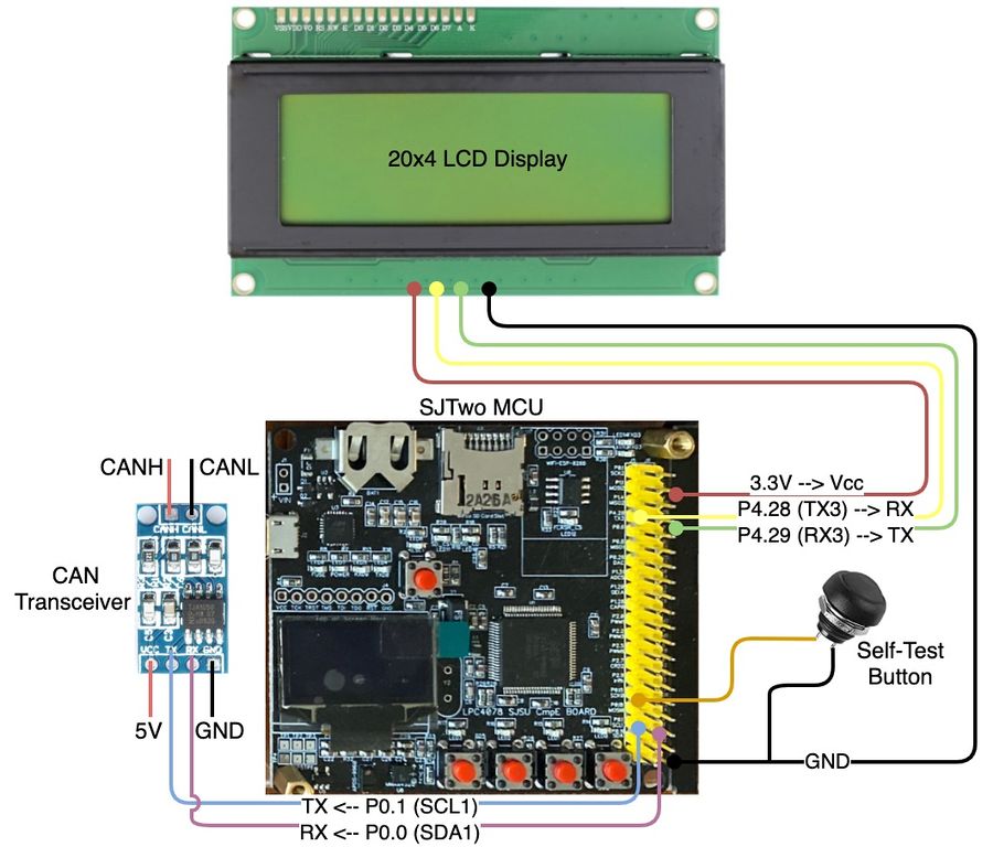
| P4.28 (TX3) | RX | LCD Rx data line | UART 3 |
| P4.29 (RX3) | TX | LCD Tx data line | UART 3 |
| P0.1 (SCL1) | CAN transceiver (Tx) | CAN transmit | CAN |
| P0.0 (SDA1) | CAN transceiver (Rx) | CAN receive | CAN |
| Vcc 3.3V | Vcc (Red wire) | Vcc | |
| GND | GND (Black wire) | Ground |
Software Design
<List the code modules that are being called periodically.>
Technical Challenges
< List of problems and their detailed resolutions>
Mobile Application
<Picture and link to Gitlab>
Hardware Design
Software Design
<List the code modules that are being called periodically.>
Technical Challenges
< List of problems and their detailed resolutions>
Conclusion
<Organized summary of the project>
<What did you learn?>
Project Video
Project Source Code
- Git Project Link: Tesla Model RC
Advise for Future Students
<Bullet points and discussion>
