Difference between revisions of "S20: Bucephalus"
Proj user2 (talk | contribs) (→Hardware Integration:- Printed Circuit Board) |
Proj user2 (talk | contribs) (→Hardware Integration:- Printed Circuit Board) |
||
| Line 567: | Line 567: | ||
| − | To avoid all the above challenges We designed the custom PCB using EasyEDA in which we implemented connections for all the controller modules(SJTwo Board LPC4078) all communicating/sending data via CAN bus. The data is sent by individual sensors to the respective controllers. GPS and Compass are connected to Geographical Controller. RPM sensor, DC and Servo Motors are connected to Motor Controller. Ultrasonic are connected to Bridge and Sensor Controller. LCD is connected to Driver Controller. Bluetooth is connected to Bridge and Sensor Controller. CAN Bus is implemented using CAN Transceivers SN65HVD230 terminated by 120 Ohms; with PCAN for monitoring CAN Debug Messages and Data. Some Components need 5V while some sensors worked on 3.3V power supply. Also it was difficult to use separate USB's to power up all boards.Hence we used CorpCo breadboard power supply 3.3V/5V. PCB was sent to fabrication to JLCPCB China which provided PCB with MOQ of 5 with the lead time of 1 week. We implemented 2 layers of PCB with most of the parts in top layer. We implemented rectangular header connector for SJTwo boards, RPM sensor, DC & Servo Motor | + | To avoid all the above challenges We designed the custom PCB using EasyEDA in which we implemented connections for all the controller modules(SJTwo Board LPC4078) all communicating/sending data via CAN bus. The data is sent by individual sensors to the respective controllers. GPS and Compass are connected to Geographical Controller. RPM sensor, DC and Servo Motors are connected to Motor Controller. <br> |
| − | + | Ultrasonic are connected to Bridge and Sensor Controller. LCD is connected to Driver Controller. Bluetooth is connected to Bridge and Sensor Controller. CAN Bus is implemented using CAN Transceivers SN65HVD230 terminated by 120 Ohms; with PCAN for monitoring CAN Debug Messages and Data. Some Components need 5V while some sensors worked on 3.3V power supply. Also it was difficult to use separate USB's to power up all boards.Hence we used CorpCo breadboard power supply 3.3V/5V. <br> | |
| − | + | PCB was sent to fabrication to JLCPCB China which provided PCB with MOQ of 5 with the lead time of 1 week. We implemented 2 layers of PCB with most of the parts in top layer GPS sensor and Compass sensor. We implemented rectangular header connector for SJTwo boards, RPM sensor, DC & Servo Motor on the bottom layer. There were 2 iterations of this board.<br> | |
| − | There were 2 iterations of this board. | + | <b> Challenges</b>We also need to change the header for LCD since it was having different pitch. |
<br><br><br> | <br><br><br> | ||
Revision as of 03:21, 5 May 2020
Contents
ABSTRACT
Bucephalus is a Self Driving RC car using CAN communication based on FreeRTOS(Hard RTOS). The RC car takes real time inputs and covert it into the data that can be processed to monitor and control to meet the desired requirements. In this project, we aim to design and develop a self-driving car that autonomously navigates from the current location to the destination (using Waypoint Algorithm )which is selected through an Android application and at the same time avoiding all the obstacles in the path using Obstacle avoidance algorithm . It also Increases or Decreases speed on Uphill and downhill (using PID Algorithm)as well as applies breaks at required places. The car comprises of 4 control units communicating with each other over the CAN Bus using CAN communication protocol, each having a specific functionality that helps the car to navigate to its destination successfully.
INTRODUCTION
Objectives of the RC Car:-
1) Driver Controller:- Detection and avoidance of the obstacles coming in the path of the RC car by following Obstacle detection avoidance.
2) Geographical Controller:- Getting the GPS coordinates from the Android Application and traveling to that point using Waypoint Algorithm
3) System hardware communication using PCB Design.
4) Bridge and Sensor Controller:- Communication between the Driver Board and Android Mobile Application using wireless bluetooth commmunication.
5) Motor Controller:- Control the Servo Motor for Direction and DC motor for speed. Implementation of PID Algorithm on normal road uphill and down hill to maintain speed
The project is divided into six main modules:
|
CORE MODULES OF RC CAR | ||||
|---|---|---|---|---|
| ||||
Team Members & Responsibilities
<Team Picture>
Bucephalous GitLab - [1]
- Mohit Ingale GitLab LinkedIn
- Driver and LCD Controller
- Hardware Integration (PCB Designing)
- Testing Team / Code Reviewers
- Shreya Patankar GitLab LinkedIn
- Geographical Controller
- Hardware Integration (PCB Designing)
- Testing Team / Code Reviewers
- Wiki Page
- Nicholas Kaiser GitLab LinkedIn
- Bridge and Sensor Controller
- Wiki Page
- Hardware Integration (PCB Designing)
- Hari Haran Kura GitLab LinkedIn
- Motor Controller
- Testing Team / Code Reviewers
- Hardware Integration (PCB Designing)
- Abhinandan Burli GitLab LinkedIn
- Driver and LCD Controller
- Testing Team / Code Reviewers
- Hardware Integration (PCB Designing)
Schedule
| Week# | Start Date | End Date | Task | Status |
|---|---|---|---|---|
| 1 | 02/16/2020 | 02/22/2020 |
|
|
| 2 | 02/23/2020 | 02/29/2020 |
|
|
| 3 | 03/01/2020 | 03/07/2020 |
|
|
| 4 | 03/08/2020 | 03/14/2020 |
|
|
| 5 | 03/15/2020 | 03/21/2020 |
|
|
| 6 | 03/22/2020 | 03/28/2020 |
|
|
| 7 | 03/29/2020 | 04/04/2020 |
|
|
| 8 | 04/05/2020 | 04/11/2020 |
|
|
| 9 | 04/12/2020 | 04/18/2020 |
|
|
| 10 | 04/19/2020 | 04/25/2020 |
|
|
| 11 | 04/26/2020 | 05/02/2020 |
|
|
| 12 | 05/03/2020 | 05/09/2020 |
|
|
| 13 | 05/10/2020 | 05/16/2020 |
|
|
| 14 | 05/17/2020 | 05/23/2020 |
|
|
Parts List & Cost
| Item# | Part Desciption | Vendor | Qty | Cost |
|---|---|---|---|---|
| 1 | RC Car Chassis | Traxxas | 1 | $250.00 |
| 2 | Lithium-Ion Battery | 1 | ||
| 3 | Battery Charger | 1 | ||
| 4 | Tap Plastics Acrylic Sheet | 1 | ||
| 5 | Ultrasonic Sensors | Amazon [2] | 4 | |
| 6 | GPS Module | 1 | ||
| 7 | GPS Antenna | 1 | ||
| 8 | Compass Module | 1 | ||
| 9 | UART LCD Display | 1 | ||
| 10 | Bluetooth Module | 1 | ||
| 11 | CAN Transceivers SN65HVD230DR | 15 | Free Samples | |
| 12 | Sjtwo Board | Preet | 4 | $50.00 |
| 13 | 12" Pipe | 1 | ||
| 14 | Android Mobile Phone | 1 | ||
| 15 | Sensor Mounts | 4 |
Hardware Integration:- Printed Circuit Board
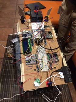
We Initially started with a very basic design of mounting all the hardware on a cardboard sheet for our first round of Integrated hardware testing.
Challenges:- The wires were an entire mess and the car could not navigate properly due to the wiring issues as all the wires were entangling and few had connectivity issues.
Hence we decided to go for a basic dot matrix Design before finalizing our final PCB Design as a Prototype board for testing if anything goes haywire.
The Prototype Board just before the actual PCB board was created on a dot matrix PCB along with all the hardware components for the Intermediate Integrated testing phase is as follows:
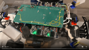
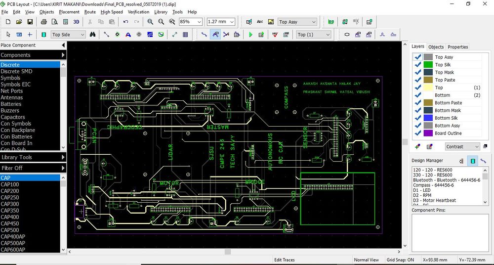
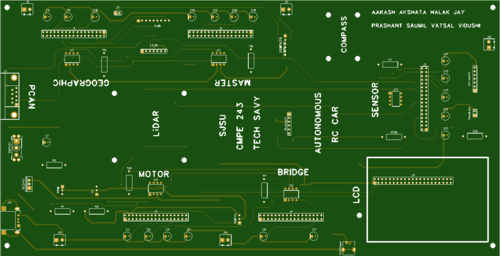
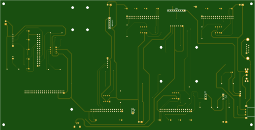
To avoid all the above challenges We designed the custom PCB using EasyEDA in which we implemented connections for all the controller modules(SJTwo Board LPC4078) all communicating/sending data via CAN bus. The data is sent by individual sensors to the respective controllers. GPS and Compass are connected to Geographical Controller. RPM sensor, DC and Servo Motors are connected to Motor Controller.
Ultrasonic are connected to Bridge and Sensor Controller. LCD is connected to Driver Controller. Bluetooth is connected to Bridge and Sensor Controller. CAN Bus is implemented using CAN Transceivers SN65HVD230 terminated by 120 Ohms; with PCAN for monitoring CAN Debug Messages and Data. Some Components need 5V while some sensors worked on 3.3V power supply. Also it was difficult to use separate USB's to power up all boards.Hence we used CorpCo breadboard power supply 3.3V/5V.
PCB was sent to fabrication to JLCPCB China which provided PCB with MOQ of 5 with the lead time of 1 week. We implemented 2 layers of PCB with most of the parts in top layer GPS sensor and Compass sensor. We implemented rectangular header connector for SJTwo boards, RPM sensor, DC & Servo Motor on the bottom layer. There were 2 iterations of this board.
ChallengesWe also need to change the header for LCD since it was having different pitch.
CAN Communication
<Talk about your message IDs or communication strategy, such as periodic transmission, MIA management etc.>
Hardware Design
<Show your CAN bus hardware design>
DBC File
Bridge and Sensor Controller
<Picture and link to Gitlab>
Hardware Design
Software Design
<List the code modules that are being called periodically.>
Technical Challenges
< List of problems and their detailed resolutions>
Motor Controller
<Picture and link to Gitlab>
Hardware Design
Software Design
<List the code modules that are being called periodically.>
Technical Challenges
< List of problems and their detailed resolutions>
Geographical Controller
<Picture and link to Gitlab>
Hardware Design
Software Design
<List the code modules that are being called periodically.>
Technical Challenges
< List of problems and their detailed resolutions>
Driver Module
<Picture and link to Gitlab>
Hardware Design
Software Design
<List the code modules that are being called periodically.>
Technical Challenges
< List of problems and their detailed resolutions>
Mobile Application
<Picture and link to Gitlab>
Hardware Design
Software Design
<List the code modules that are being called periodically.>
Technical Challenges
< List of problems and their detailed resolutions>
Conclusion
<Organized summary of the project>
<What did you learn?>
Project Video
Project Source Code
Advise for Future Students
<Bullet points and discussion>
Acknowledgement
=== References ===
