Difference between revisions of "S19: Run D.B.C"
Proj user10 (talk | contribs) (→BRIDGE CONTROLLER) |
Proj user10 (talk | contribs) (→Hardware Interface of GPS Module) |
||
| Line 658: | Line 658: | ||
=== Hardware Interface of GPS Module === | === Hardware Interface of GPS Module === | ||
| − | [[File: | + | [[File:RUN DBC geo sch.jpeg | 800px]] |
=== <font color="0000FF"> Software Design </font> === | === <font color="0000FF"> Software Design </font> === | ||
Revision as of 01:59, 18 May 2019
Contents
- 1 ABSTRACT
- 2 INTRODUCTION & OBJECTIVES
- 3 SCHEDULE
- 4 BILL OF MATERIALS (GENERAL PARTS)
- 5 HARDWARE INTEGRATION PCB
- 6 CAN NETWORK
- 7 ANDROID MOBILE APPLICATION
- 8 BRIDGE CONTROLLER
- 9 Design and Implementation
- 10 MASTER CONTROLLER
- 11 MOTOR CONTROLLER
- 12 SENSOR CONTROLLER
- 13 CONCLUSION
- 14 Grading Criteria
ABSTRACT
The RUN-D.B.C project, involves the design and construction of an autonomously navigating RC car. Development of the R.C car's subsystem modules will be divided amongst and performed by seven team members. Each team member will lead or significantly contribute to the development of at least one subsystem.
INTRODUCTION & OBJECTIVES
|
RC CAR OBJECTIVES | ||||
|---|---|---|---|---|
| ||||
|
TEAM OBJECTIVES | ||||
|---|---|---|---|---|
| ||||
|
CORE MODULES OF RC CAR | ||||
|---|---|---|---|---|
| ||||
|
PROJECT MANAGEMENT ADMINISTRATION ROLES | ||||
|---|---|---|---|---|
| ||||
|
TEAM MEMBERS & RESPONSIBILITIES | ||||
|---|---|---|---|---|
|
Team Members |
Administrative Roles |
Technical Roles | ||
|
|
| ||
|
| |||
|
|
| ||
|
|
| ||
|
| |||
|
| |||
|
| |||
SCHEDULE
|
TEAM MEETING DATES & DELIVERABLES | ||||
|---|---|---|---|---|
|
Week# |
Date Assigned |
Deliverables |
Status | |
| 1 | 2/16/19 |
|
| |
| 2 | 2/24/19 |
|
| |
| 3 | 3/3/19 |
|
| |
| 4 | 3/10/19 |
|
| |
| 5 | 3/17/19 |
|
| |
| 6 | 3/24/19 |
|
| |
| 7 | 3/31/19 |
|
| |
| 8 | 4/7/19 |
|
| |
| 9 | 4/14/19 |
|
| |
| 10 | 4/21/19 |
|
| |
| 11 | 4/28/19 |
|
| |
| 12 | 5/5/19 |
|
| |
| 13 | 5/12/19 |
|
| |
| 14 | 5/22/19 |
|
| |
BILL OF MATERIALS (GENERAL PARTS)
|
MICRO-CONTROLLERS | ||||
|---|---|---|---|---|
|
PART NAME |
PART MODEL & SOURCE |
QUANTITY |
COST PER UNIT (USD) | |
|
|
|
| |
|
RC CAR | ||||
|---|---|---|---|---|
|
PART NAME |
PART MODEL & SOURCE |
QUANTITY |
COST PER UNIT (USD) | |
|
|
| ||
|
|
| ||
|
|
| ||
HARDWARE INTEGRATION PCB
Hardware Design
The hardware integration PCB was designed with two goals:
1. Minimize the footprint of the onboard electronics
2. Minimize the chances of wires disconnecting, during drives
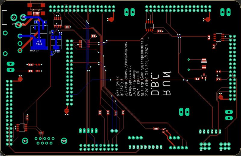
To accomplish these goals, all controllers were directly connected to the board's 34 pin header arrays, while all sensors were connected to the board, using ribbon cables and locking connectors. The master controller's header pins were inverted and then connected to a header array on top of the PCB, while the other controllers were mounted to the bottom. This guaranteed secure power and signal transmission paths, throughout the system.
The board consisted of 4 layers:
Signal
3.3V
5.0V
GND
Technical Challenges
Design
- Balancing priorities between HW design and getting a working prototype
- Finalizing a PCB design, when some components and module designs are not nailed down
Assembly
- DB-9 connector for CAN dongle was wired backwards in the PCB design. Because there are several unused pins, we were able to just.
- Spacing for headers with clips were not accounted for properly in the design. two of them are very close. It's a tight fit, but it should work.
- Wireless antenna connector on master board not accounted for in footprint, it may have to be removed to avoid interference with one connector.
Bill Of Materials
|
HARDWARE INTEGRATION PCB | ||||
|---|---|---|---|---|
|
PART NAME |
PART MODEL |
QUANTITY |
COST PER UNIT (USD) | |
|
|
|
|
| |
CAN NETWORK
<Talk about your message IDs or communication strategy, such as periodic transmission, MIA management etc.>
Hardware Design
<Show your CAN bus hardware design>
DBC File
<Gitlab link to your DBC file> <You can optionally use an inline image>
ANDROID MOBILE APPLICATION
<Picture and link to Gitlab>
Hardware Design
Software Design
<List the code modules that are being called periodically.>
Technical Challenges
<Bullet or Headings of a module>
Bug Tracking
<Problem Summary> <Problem Resolution>
Bill Of Materials
|
ANDROID MOBILE APPLICATION | ||||
|---|---|---|---|---|
|
PART NAME |
PART MODEL |
QUANTITY |
COST PER UNIT (USD) | |
|
|
|
|
| |
BRIDGE CONTROLLER
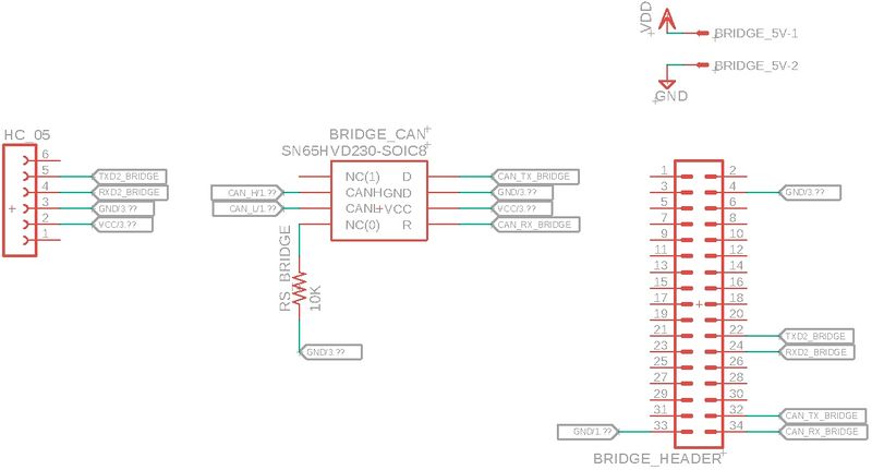
Hardware Design
Software Design
<List the code modules that are being called periodically.>
Technical Challenges
<Problem Summary> <Problem Resolution>
Bill Of Materials
|
BRIDGE CONTROLLER | ||||
|---|---|---|---|---|
|
PART NAME |
PART MODEL |
QUANTITY |
COST PER UNIT (USD) | |
|
|
| ||
GEOGRAPHIC CONTROLLER
Design and Implementation
The geographical controller is responsible for providing the required directions for the car to reach its destination. This is achieved using the Adafruit MTK3339 Ultimate GPS module and the CMPS12 9DOF compass module to obtain the heading and bearing angle. The co-ordinates for the START and STOP positions are entered in the app, which are in turn sent to the geographical controller for obtaining the checkpoints and making sure the car reaches the destination. These co-ordinates are transmitted via Bluetooth. Checkpoints are plotted around the whole campus, and are sent to the geographical module by the bridge module one by one as and when they are reached.
GPS Module
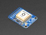
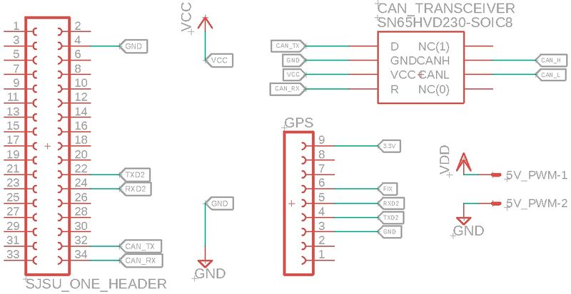
The GPS module chosen is from Adafruit (MTK3339 Ultimate GPS module). An external antenna was also used in order to parse the GPS data more efficiently. The GPS module uses UART for communicating with the SJOne board. The baud rate for the UART interface has to be initialized twice in the code: 9600 baud rate at first and then again at 57600 baud rate.
The GPS module comes with a GPS lock, which essentially means the GPS has enough information from the satellites to know the location. This lock is indicated by an LED, which glows once in every 15 seconds as opposed to glowing every 1-2 seconds when the GPS doesn’t have a lock. The parsing of data from the GPS is in terms of NMEA sentences, each of which has a specific functionality. Out of the several NMEA sentences, $GPRMC was used. It provides the minimum required information like latitudes and longitudes. The $GPRMC sentence is separated by commas, which the user has to parse in order to get useful data out of the module. The strtok() function is used to parse data from the GPS module, with comma(,) as the delimiter.
Hardware Interface of GPS Module
Software Design
<List the code modules that are being called periodically.>
Technical Challenges
<Bullet or Headings of a module>
Bug Tracking
<Problem Summary> <Problem Resolution>
Bill Of Materials
|
GEOGRAPHIC CONTROLLER | ||||
|---|---|---|---|---|
|
PART NAME |
PART MODEL |
QUANTITY |
COST PER UNIT (USD) | |
|
|
| ||
|
|
| ||
MASTER CONTROLLER
<Picture and link to Gitlab>
Hardware Design
The master controller is primarily interfaced with the other controllers over CAN bus. The other main interface is control of the LCD display for debug data, which communicates over UART.
Software Design
<List the code modules that are being called periodically.>
- LCD display
- CAN read and send
- Navigation
- obstacle avoidance
- steer to checkpoint
Technical Challenges
<Bullet or Headings of a module>
Bug Tracking
<Problem Summary> <Problem Resolution>
Bill Of Materials
|
MASTER CONTROLLER | ||||
|---|---|---|---|---|
|
PART NAME |
PART MODEL |
QUANTITY |
COST PER UNIT (USD) | |
|
|
|
|
| |
MOTOR CONTROLLER
<Picture and link to Gitlab>
Hardware Design
Software Design
<List the code modules that are being called periodically.>
Technical Challenges
<Bullet or Headings of a module>
- We had to change the PWM driver to hard code the sys_clock frequency. We found solution.
- Original encoder sourced is was designed to be a knob, not a motor encoder. The additional rotational resistance caused vibrations and resulted in it becoming disconnected from the motor shaft several times. The solution was to us a slightly more expensive encoder, designed for higher speed continuous operation on a motor.
Bug Tracking
<Problem Summary> <Problem Resolution>
Bill Of Materials
|
MOTOR CONTROLLER | ||||
|---|---|---|---|---|
|
PART NAME |
PART MODEL |
QUANTITY |
COST PER UNIT (USD) | |
|
|
|
|
| |
SENSOR CONTROLLER
Hardware Design
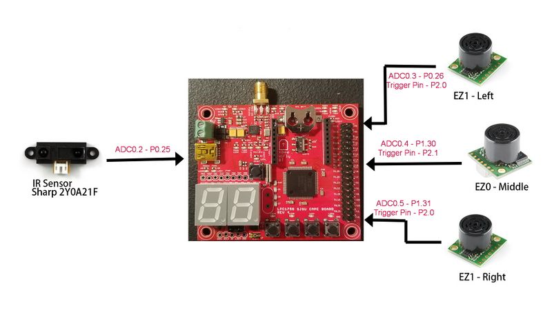
| Part Number | Quantity | Location on Car | Range | Voltage Requirement | Link |
|---|---|---|---|---|---|
| MB1000 LV-MaxSonar-EZ0 | 1 | Front - Middle | 6 in - 254 in (0.15 m - 6.45m) | 3.3V | https://www.maxbotix.com/Ultrasonic_Sensors/MB1000.htm |
| MB1010 LV-MaxSonar-EZ1 | 2 | Front - Left Front - Right |
6 in - 254 in (0.15 m - 6.45m) | 3.3V | https://www.maxbotix.com/Ultrasonic_Sensors/MB1010.htm |
| Infrared Proximity Sensor - Sharp GP2Y0A21YK | 1 | Back - Middle | 10 cm - 80cm | 5V | https://www.sparkfun.com/products/242 |
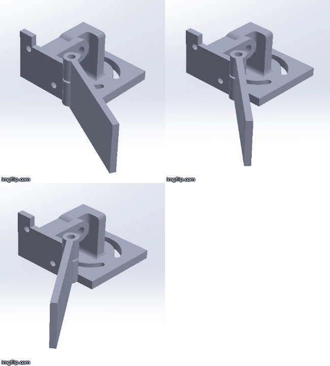
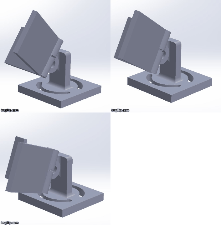
We put in a lot of thoughts on how sensors should be placed on the car. In order to facilitate easy adjustment of sensor direction, we incorporated circular grooves in the sensor bases so the mount left/right direction can be adjusted on the fly. The hinge of the sensor mount also allows sensors to be tiled up and down, together with the sensor mount, offering two degrees of freedom.
CAD Design
Picture on the left shows the hinge of the sensor guard can be adjusted to minimize the amount of interference between sensors.
Picture on the right shows the hinge of the sensor mount allows sensors to be tiled up and down.
Placement for the Ultrasonic Sensors
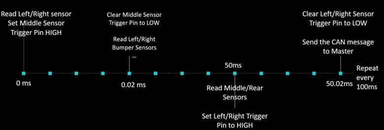
We realized that when the sensors are turned on, the left and right sensors output ultrasonic waves that can interfere that of the middle sensor, even though we purposefully place them in different iterations of the periodic tasks. However, by placing the middle sensor on a higher ground, interference decreases. Moreover, by attaching two guard pieces on the left/right sensors we can further minimize the amount of interference between sensors. The integrity of sensor readings was rigorously tested with the guards to make sure they don’t lead to inaccurate readings for left and right sensors.
Software Design
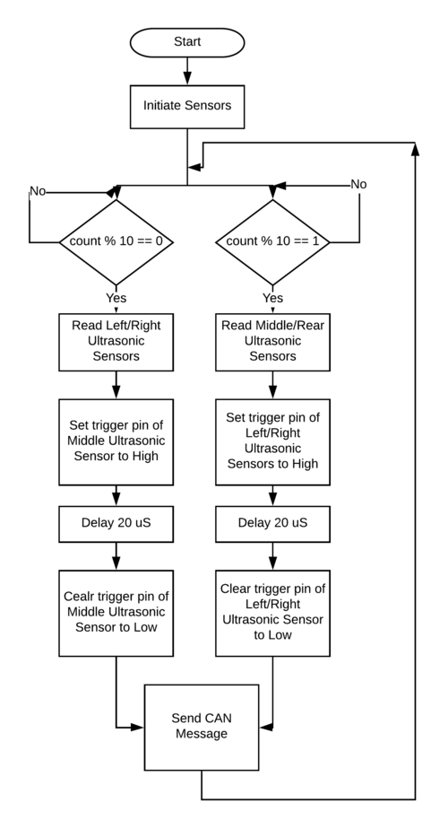
Flowchart
Timing Diagram
Technical Challenges
Sensor Interference
We saw a lot of interference between the front 3 sensors. We were able to overcome the issue with both hardware and software tweaks:
- Higher placement of middle ultrasonic sensor and interference guard for the left and right sensors
- Instead of leaving the RX pin of the sensors unconnected, which causes the sensors to output ultrasonic waves continuously, we toggle the RX pin to turn off sensor ranging and only allow wave output when we need it. The periodic callback function is also written in a way that staggers sensor trigger and sensor reading in a way to ensure sufficient time before ADC read.
Power Deficiency
At first, when the sensors are tested as an individual module, everything is fine. However, when the modules are integrated towards the end of the semester, suddenly they all start to output erroneous data. After many hours of troubleshooting we realized that our power supply was not enough to power everything on the car. We fixed it by having battery with higher power output.
HR-04 unstable reading
At first, our left and right sensors are two HC-SR04 modules from Ebay. However when we tested them during obstacle avoidance we realized that they have very narrow range and can sometimes not see what is in front of them. As a result we switched to more expensive, but reliable Maxbotix EZ line of sensors.
The ADC module can only read 3.3V
Our middle sensor was having fluctuating readings that were very difficult to filter. After hours of testing we realized that we are connecting it to 5V supply but uses the ADC of SJone board to read distance value. As the ADCs of SJone cannot read above 3.3V, this is the reason for the erroneous data and after we switched the sensor to 3.3V supply, the problem disappeared.
Bug Tracking
Slow car response to obstacle due to large queue size (running average)
During our first try at obstacle avoidance we found that the car reacts very slowly to obstacles, even though the sensor update rate is 10Hz. Later we found out that the reason is because of our queue implementation. We used to have a very large queue to calculate running average. This filters out spikes but also means when an obstacle is detected it takes very long time for the running average to be updated.
- Solution: Decrease the queue size and find median value instead of average to output to the master module.
Bill Of Materials
|
SENSOR CONTROLLER | ||||
|---|---|---|---|---|
|
PART NAME |
PART MODEL |
QUANTITY |
COST PER UNIT (USD) | |
|
|
| ||
|
|
| ||
|
|
| ||
|
|
| ||
CONCLUSION
<Organized summary of the project>
<What did you learn?>
Project Video
Project Source Code
Advice for Future Students
<Bullet points and discussion>
Grading Criteria
- How well is Software & Hardware Design described?
- How well can this report be used to reproduce this project?
- Code Quality
- Overall Report Quality:
- Software Block Diagrams
- Hardware Block Diagrams
- Schematic Quality
- Quality of technical challenges and solutions adopted.
