Difference between revisions of "S19: Hot Wheels"
Proj user13 (talk | contribs) (→DC Motor) |
Proj user13 (talk | contribs) (→DC Motor) |
||
| Line 357: | Line 357: | ||
===== DC Motor ===== | ===== DC Motor ===== | ||
[[File:CMPE243_F16_SnF_DCMotor.png|thumb|right|200px|DC Motor]] | [[File:CMPE243_F16_SnF_DCMotor.png|thumb|right|200px|DC Motor]] | ||
| + | Our car came with Titan 12T 550 brushed motor and waterproof ESC. The ESC drives the DC motor based on the Pulse Width modulation (PWM) applied to it. The power supply required for this motor is 8.4 V. Maximum speed of upto 30mph can be achieved. The rotational speed is proportional to the EMF generated in its coil and the torque is proportional to the current.The main connection pins driving the motor are VCC,GND and the Control pin (PWM). The pin P2.1 of SJ-one board is connected to supply the required PWM to the motor. The basic working principle of DC motor is illustrated in the following figure : Since the preprogrammed controller has to be replaced by using our design ,the DC motor is then tested with Digital Oscilloscope for getting the frequency of operation and equivalent PWM values for full throttle condition in the forward as well as backward condition. It was observed from the waveform that the frequency of operation is 100Hz. The range of operational duty cycle is 10% to 20% with 15% being the neutral value or the stop condition. In order to accelerate the car a PWM value in the range of 15.6%-20.0% is applied. The 15.6 is the minimum pickup PWM that should be supplied in order to get the car moving at full load. | ||
===== Servo Motor ===== | ===== Servo Motor ===== | ||
Revision as of 23:57, 11 May 2019
Contents
Project Title
<Team Name>
Abstract
In the HOT WHEELS project, we plan to design and construct an autonomously navigating, electric R.C car which uses CAN bus for internal communication and an android app for selecting car destination. Development of the R.C car's subsystem modules will be divided amongst the eight team members.
Introduction
The project was divided into N modules:
- Sensor ...
- Motor..
- ...
- Android
Team Members & Responsibilities
<Team Picture>
Gitlab Project Link - [1]
<Provide ECU names and members responsible> <One member may participate in more than one ECU>
- Master Control
- Kailash Chakravarty
- Sensor
- Rishabh Sheth
- Motor
- Kriti Hedau
- Tahir Rawn
- Geographical
- Harmeen Joshi
- Nandini Shankar
- Communication Bridge Controller & Android Application
- Swanand Sapre
- Aquib Mulani
- Code Review & Commit Approvers
- Rishabh Sheth
- Nandini Shankar
- Kailash Chakravarty
Schedule
| Week# | Date | Task | Status | Completion Date |
|---|---|---|---|---|
| 1 | 02/12/19 |
|
|
|
| 2 | 02/17/19 |
|
|
|
| 3 | 02/26/19 |
|
|
|
| 4 | 03/05/19 |
|
|
|
| 5 | 03/12/19 |
|
|
|
| 6 | 03/19/19 |
|
|
|
| 7 | 03/26/19 |
|
|
|
| 8 | 04/02/19 |
|
|
|
| 9 | 04/09/19 |
|
|
|
| 10 | 04/16/19 |
|
|
|
| 11 | 04/23/19 |
|
|
|
| 12 | 04/30/19 |
|
|
|
| 13 | 05/07/19 |
|
|
|
| 14 | 05/14/19 |
|
|
|
| 15 | 05/22/19 |
|
|
|
Parts List & Cost
| Item# | Part Desciption | Vendor | Qty | Cost |
|---|---|---|---|---|
| 1 | RC Car | Traxxas | 1 | $250.00 |
| 2 | CAN Transceivers MCP2551-I/P | Microchip [2] | 8 | Free Samples |
Printed Circuit Board
<Picture and information, including links to your PCB>
CAN Communication
<Talk about your message IDs or communication strategy, such as periodic transmission, MIA management etc.>
Hardware Design
<Show your CAN bus hardware design>
DBC File
Gitlab link to your DBC file [3]
VERSION "0.1.0"
BU_: MASTER SENSOR MOTORIO GEO APP
BO_ 220 MOTORIO_CMD: 4 MASTER
SG_ MOTORIO_CMD_Direction : 0|8@1+ (1,0) [0|2] "" MOTORIO
BO_ 210 ULTRA_CMD: 4 SENSOR
SG_ SENSOR_SONARS_FrontDistance : 0|8@1+ (1,0) [2|100] "" MASTER
BO_ 250 DISTANCE: 4 GEO
SG_ DISTANCE_FinalDistance : 0|16@1+ (0.1,0) [0|0] "" MASTER
BO_ 102 BLUETOOTH: 4 APP
SG_ DISTANCE_FinalDistance : 0|16@1+ (0.1,0) [0|0] "" MASTER
CM_ BU_ MASTER "The Master controller of the car";
CM_ BU_ MOTOR "The motor controller of the car";
CM_ BU_ SENSOR "The sensor controller of the car";
CM_ BU_ GEO "The Geo controller of the car";
CM_ BU_ APP "The Bluetooth/App controller of the car";
Sensor ECU
<Picture and link to Gitlab>
MOTOR CONTROLLER
Group Members
Design & Implementation
Hardware Design
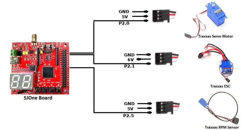
| SJOne Pin Diagram | ||
|---|---|---|
| Sr.No | Pin Number | Pin Function |
| 1 | P0.0 | CAN RX |
| 2 | P0.1 | CAN TX |
| 3 | P2.0 | Servo motor |
| 4 | P2.1 | DC motor |
| 5 | P2.5 | Speed Encoder |
- Hardware Specifications
DC Motor
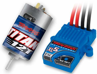
Our car came with Titan 12T 550 brushed motor and waterproof ESC. The ESC drives the DC motor based on the Pulse Width modulation (PWM) applied to it. The power supply required for this motor is 8.4 V. Maximum speed of upto 30mph can be achieved. The rotational speed is proportional to the EMF generated in its coil and the torque is proportional to the current.The main connection pins driving the motor are VCC,GND and the Control pin (PWM). The pin P2.1 of SJ-one board is connected to supply the required PWM to the motor. The basic working principle of DC motor is illustrated in the following figure : Since the preprogrammed controller has to be replaced by using our design ,the DC motor is then tested with Digital Oscilloscope for getting the frequency of operation and equivalent PWM values for full throttle condition in the forward as well as backward condition. It was observed from the waveform that the frequency of operation is 100Hz. The range of operational duty cycle is 10% to 20% with 15% being the neutral value or the stop condition. In order to accelerate the car a PWM value in the range of 15.6%-20.0% is applied. The 15.6 is the minimum pickup PWM that should be supplied in order to get the car moving at full load.
Servo Motor
RPM Sensor
Hardware Interface
Software Design
Technical Challenges
Future Counsel
Geographical Controller
<Picture and link to Gitlab>
Hardware Design
Software Design
<List the code modules that are being called periodically.>
Technical Challenges
<Bullet or Headings of a module>
Unreliable GPS lock
<Problem Summary> <Problem Resolution>
Communication Bridge Controller & LCD
<Picture and link to Gitlab>
Hardware Design
Software Design
<List the code modules that are being called periodically.>
Technical Challenges
<Bullet or Headings of a module>
Insane Bug
<Problem Summary> <Problem Resolution>
Master Module
<Picture and link to Gitlab>
Hardware Design
Software Design
<List the code modules that are being called periodically.>
Technical Challenges
<Bullet or Headings of a module>
Improper Unit Testing
<Problem Summary> <Problem Resolution>
Conclusion
<Organized summary of the project>
<What did you learn?>
Project Video
Project Source Code
Advise for Future Students
<Bullet points and discussion>

