Difference between revisions of "S19: Run D.B.C"
Proj user10 (talk | contribs) (→Hardware Design) |
Proj user22 (talk | contribs) (→Technical Challenges) |
||
| Line 771: | Line 771: | ||
<Bullet or Headings of a module> | <Bullet or Headings of a module> | ||
| − | We had to change the PWM driver to hard code the sys_clock frequency. We found solution. | + | * We had to change the PWM driver to hard code the sys_clock frequency. We found solution. |
| + | |||
| + | * Original encoder sourced is was designed to be a knob, not a motor encoder. The additional rotational resistance caused vibrations and resulted in it becoming disconnected from the motor shaft several times. The solution was to us a slightly more expensive encoder, designed for higher speed continuous operation on a motor. | ||
=== <font color="EE82EE"> Bug Tracking </font>=== | === <font color="EE82EE"> Bug Tracking </font>=== | ||
Revision as of 18:55, 5 May 2019
Contents
- 1 ABSTRACT
- 2 INTRODUCTION & OBJECTIVES
- 3 SCHEDULE
- 4 BILL OF MATERIALS (GENERAL PARTS)
- 5 HARDWARE INTEGRATION PCB
- 6 WIRING HARNESS
- 7 CAN NETWORK
- 8 ANDROID MOBILE APPLICATION
- 9 BRIDGE CONTROLLER
- 10 GEOGRAPHIC CONTROLLER
- 11 MASTER CONTROLLER
- 12 MOTOR CONTROLLER
- 13 SENSOR CONTROLLER
- 14 CONCLUSION
- 15 Grading Criteria
ABSTRACT
The RUN-D.B.C project, involves the design and construction of an autonomously navigating RC car. Development of the R.C car's subsystem modules will be divided amongst and performed by seven team members. Each team member will lead or significantly contribute to the development of at least one subsystem.
INTRODUCTION & OBJECTIVES
|
RC CAR OBJECTIVES | ||||
|---|---|---|---|---|
| ||||
|
TEAM OBJECTIVES | ||||
|---|---|---|---|---|
| ||||
|
CORE MODULES OF RC CAR | ||||
|---|---|---|---|---|
| ||||
|
PROJECT MANAGEMENT ADMINISTRATION ROLES | ||||
|---|---|---|---|---|
| ||||
|
TEAM MEMBERS & RESPONSIBILITIES | ||||
|---|---|---|---|---|
|
Team Members |
Administrative Roles |
Technical Roles | ||
|
|
| ||
|
| |||
|
|
| ||
|
|
| ||
|
| |||
|
| |||
|
| |||
SCHEDULE
|
TEAM MEETING DATES & DELIVERABLES | ||||
|---|---|---|---|---|
|
Week# |
Date Assigned |
Deliverables |
Status | |
| 1 | 2/16/19 |
|
| |
| 2 | 2/24/19 |
|
| |
| 3 | 3/3/19 |
|
| |
| 4 | 3/10/19 |
|
| |
| 5 | 3/17/19 |
|
| |
| 6 | 3/24/19 |
|
| |
| 7 | 3/31/19 |
|
| |
| 8 | 4/7/19 |
|
| |
| 9 | 4/14/19 |
|
| |
| 10 | 4/21/19 |
|
| |
| 11 | 4/28/19 |
|
| |
| 12 | 5/5/19 |
|
| |
| 13 | 5/12/19 |
|
| |
| 14 | 5/22/19 |
|
| |
BILL OF MATERIALS (GENERAL PARTS)
|
MICRO-CONTROLLERS | ||||
|---|---|---|---|---|
|
PART NAME |
PART MODEL & SOURCE |
QUANTITY |
COST PER UNIT (USD) | |
|
|
|
| |
|
RC CAR | ||||
|---|---|---|---|---|
|
PART NAME |
PART MODEL & SOURCE |
QUANTITY |
COST PER UNIT (USD) | |
|
|
| ||
|
|
| ||
|
|
| ||
HARDWARE INTEGRATION PCB
Hardware Design
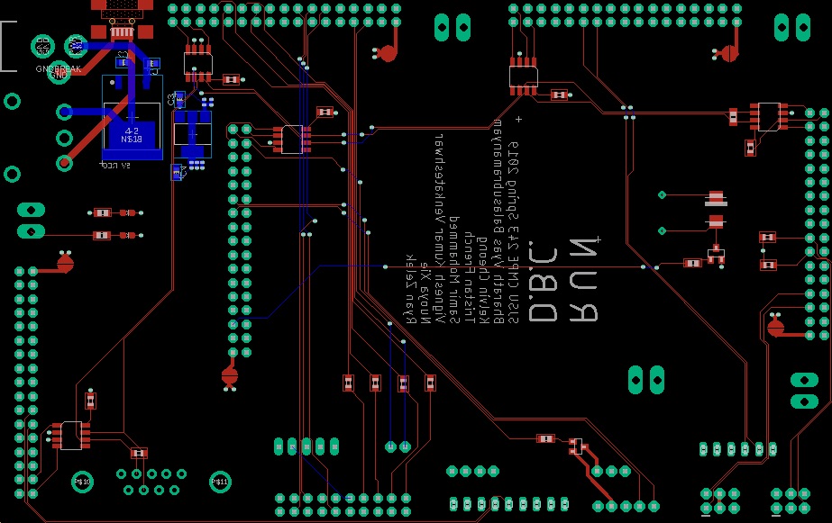
The hardware integration PCB was designed with two goals:
1. Minimize the footprint of the onboard electronics
2. Minimize the chances of wires disconnecting, during drives
To accomplish these goals, all controllers were directly connected to the board's 34 pin header arrays, while all sensors were connected to the board, using ribbon cables and locking connectors. The master controller's header pins were inverted and then connected to a header array on top of the PCB, while the other controllers were mounted to the bottom. This guaranteed secure power and signal transmission paths, throughout the system.
The board consisted of 4 layers:
Signal
3.3V
5.0V
GND
Bill Of Materials
|
HARDWARE INTEGRATION PCB | ||||
|---|---|---|---|---|
|
PART NAME |
PART MODEL |
QUANTITY |
COST PER UNIT (USD) | |
|
|
|
|
| |
WIRING HARNESS
Hardware Design
<Picture and information, including links to your PCB
Bill Of Materials
|
WIRING HARNESS | ||||
|---|---|---|---|---|
|
PART NAME |
PART MODEL |
QUANTITY |
COST PER UNIT (USD) | |
|
|
|
|
| |
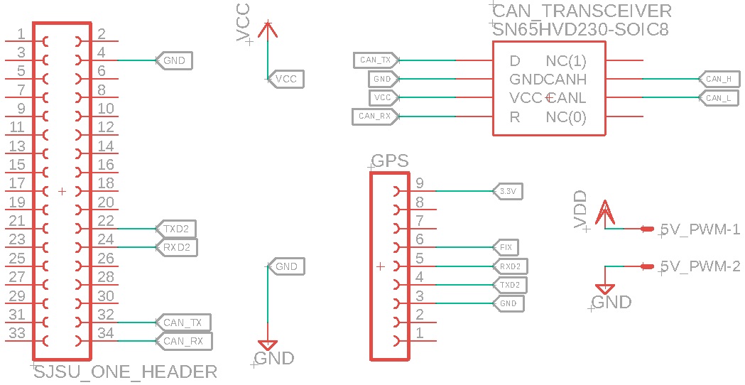
CAN NETWORK
<Talk about your message IDs or communication strategy, such as periodic transmission, MIA management etc.>
Hardware Design
<Show your CAN bus hardware design>
DBC File
<Gitlab link to your DBC file> <You can optionally use an inline image>
ANDROID MOBILE APPLICATION
<Picture and link to Gitlab>
Hardware Design
Software Design
<List the code modules that are being called periodically.>
Technical Challenges
<Bullet or Headings of a module>
Bug Tracking
<Problem Summary> <Problem Resolution>
Bill Of Materials
|
ANDROID MOBILE APPLICATION | ||||
|---|---|---|---|---|
|
PART NAME |
PART MODEL |
QUANTITY |
COST PER UNIT (USD) | |
|
|
|
|
| |
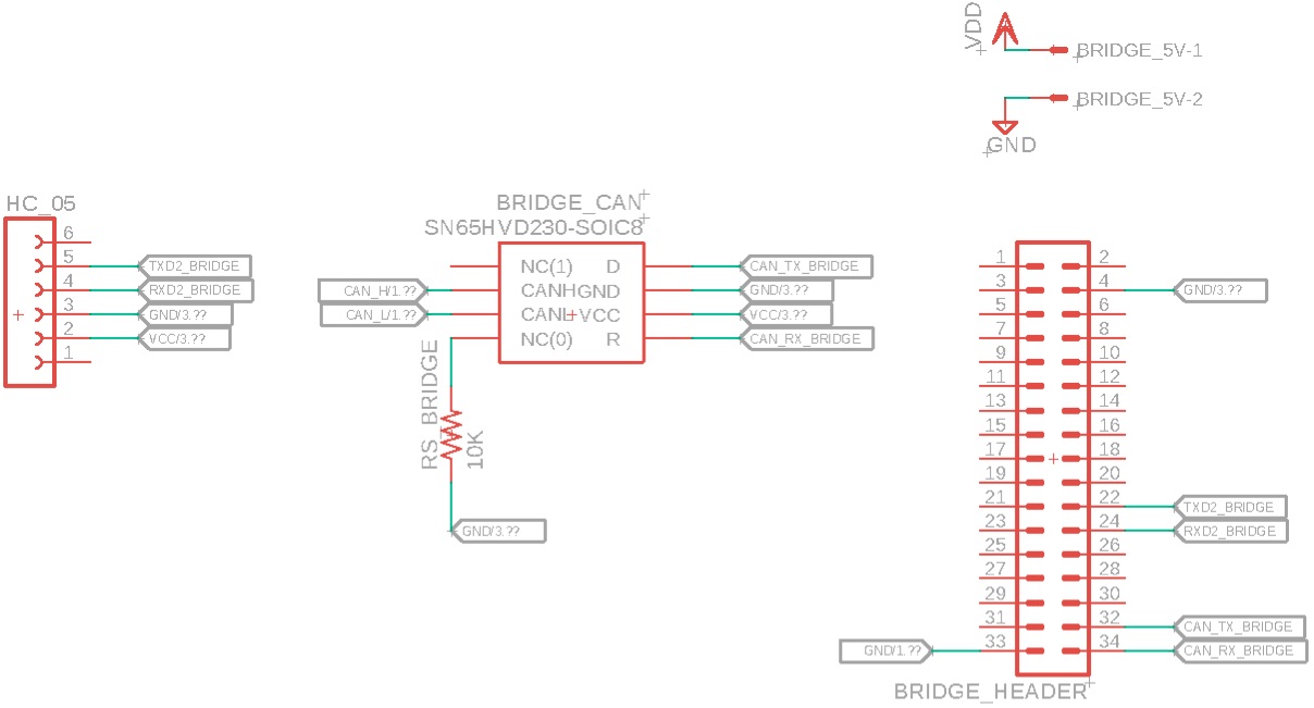
BRIDGE CONTROLLER
<Picture and link to Gitlab>
Hardware Design
Software Design
<List the code modules that are being called periodically.>
Technical Challenges
<Problem Summary> <Problem Resolution>
Bill Of Materials
|
BRIDGE CONTROLLER | ||||
|---|---|---|---|---|
|
PART NAME |
PART MODEL |
QUANTITY |
COST PER UNIT (USD) | |
|
|
| ||
GEOGRAPHIC CONTROLLER
Hardware Design
Software Design
<List the code modules that are being called periodically.>
Technical Challenges
<Bullet or Headings of a module>
Bug Tracking
<Problem Summary> <Problem Resolution>
Bill Of Materials
|
GEOGRAPHIC CONTROLLER | ||||
|---|---|---|---|---|
|
PART NAME |
PART MODEL |
QUANTITY |
COST PER UNIT (USD) | |
|
|
| ||
|
|
| ||
MASTER CONTROLLER
<Picture and link to Gitlab>
Hardware Design
Software Design
<List the code modules that are being called periodically.>
Technical Challenges
<Bullet or Headings of a module>
Bug Tracking
<Problem Summary> <Problem Resolution>
Bill Of Materials
|
MASTER CONTROLLER | ||||
|---|---|---|---|---|
|
PART NAME |
PART MODEL |
QUANTITY |
COST PER UNIT (USD) | |
|
|
|
|
| |
MOTOR CONTROLLER
<Picture and link to Gitlab>
Hardware Design
Software Design
<List the code modules that are being called periodically.>
Technical Challenges
<Bullet or Headings of a module>
- We had to change the PWM driver to hard code the sys_clock frequency. We found solution.
- Original encoder sourced is was designed to be a knob, not a motor encoder. The additional rotational resistance caused vibrations and resulted in it becoming disconnected from the motor shaft several times. The solution was to us a slightly more expensive encoder, designed for higher speed continuous operation on a motor.
Bug Tracking
<Problem Summary> <Problem Resolution>
Bill Of Materials
|
MOTOR CONTROLLER | ||||
|---|---|---|---|---|
|
PART NAME |
PART MODEL |
QUANTITY |
COST PER UNIT (USD) | |
|
|
|
|
| |
SENSOR CONTROLLER
<Picture and link to Gitlab>
Hardware Design
Software Design
<List the code modules that are being called periodically.>
Technical Challenges
<Bullet or Headings of a module>
Had to change PWM driver for sys_clock, hardcoded number was needed. We found solution.
Bug Tracking
<Problem Summary> <Problem Resolution>
Bill Of Materials
|
SENSOR CONTROLLER | ||||
|---|---|---|---|---|
|
PART NAME |
PART MODEL |
QUANTITY |
COST PER UNIT (USD) | |
|
|
| ||
|
|
| ||
|
|
| ||
|
|
| ||
CONCLUSION
<Organized summary of the project>
<What did you learn?>
Project Video
Project Source Code
Advice for Future Students
<Bullet points and discussion>
Grading Criteria
- How well is Software & Hardware Design described?
- How well can this report be used to reproduce this project?
- Code Quality
- Overall Report Quality:
- Software Block Diagrams
- Hardware Block Diagrams
- Schematic Quality
- Quality of technical challenges and solutions adopted.


