Difference between revisions of "F18: 2048"
Proj user16 (talk | contribs) (→Printed Circuit Board (PCB)) |
Proj user16 (talk | contribs) (→Printed Circuit Board (PCB)) |
||
| Line 302: | Line 302: | ||
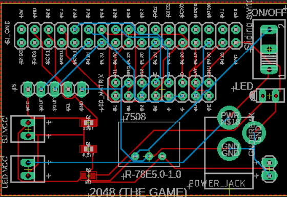
[[File:PCBLayout.png|700px|thumb|left|PCB Layout]] | [[File:PCBLayout.png|700px|thumb|left|PCB Layout]] | ||
</td> | </td> | ||
| − | |||
=== Software Design === | === Software Design === | ||
Revision as of 06:36, 19 December 2018
Contents
2048
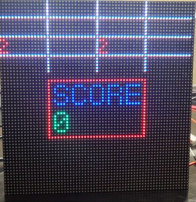
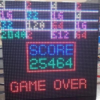
game setup image
Abstract
2048 is a game having a grid of numbered tiles (i.e., a power of 2) to combine them to create a tile with the number 2048. It is usually played on a 4x4 grid with tiles that slide smoothly when a player moves them towards the right, left, up or down. Every time a new tile will randomly appear in an empty spot on the display with a value of either 2 or 4. If two tiles of the same number collide then they will merge into one tile with a value of the sum of those two tiles. The game continues until no merge is possible. The game uses RGB LED matrix to display the 4x4 game grid and the scores. The player is given a choice to choose thumb joystick or an onboard accelerometer to give direction inputs; left, right, up and down. The Game Logic and the display are updated using two FreeRTOS tasks.
Objectives & Introduction
The primary goal of this project is to develop 2048 game with FreeRTOS using SJone Board and to drive the LED matrix to display the 4x4 game grid. The game's objective is to slide numbered tiles on a grid to combine them to create a tile with the number 2048. The player is given the choice to choose between the thumb joystick and an onboard accelerometer to give directions.
Objectives:
- Write drivers to display number grid, score on the RGB LED matrix and update the display continuously.
- Write drivers to give directions from the input devices (joystick/accelerometer).
- Implement game algorithm for movement of blocks in real-time, generate a random tile (2 or 4) and update scores.
- Implement game over logic once the grid is full and no merges are possible.
- Create FeeRTOS tasks for display and game logic and understand the communication and synchronization between them.
Team Members & Responsibilties
- Deepak Shivani
- Hardware Design
- LED Display Drivers
- PCB Design
- Navyashree Chandraiah
- Game Logic
- PCB Design
- Sai Kiran Duggineni
- LED Display Application
- Shrusti Shashidhar
- Joystick Drivers
- Game Logic
- Vishal Yarabandi
- LED Display Drivers
- Wiki Schedule
Schedule
| Week# | Start Date | Task | Status | Completion Date |
|---|---|---|---|---|
| 1 | 09/18 |
|
|
|
| 2 | 10/09 |
|
|
|
| 3 | 10/16 |
|
|
|
| 4 | 10/23 |
|
|
|
| 5 | 10/30 |
|
|
|
| 6 | 11/06 |
|
|
|
| 7 | 11/13 |
|
|
|
| 8 | 11/20 |
|
|
|
| 9 | 11/27 |
|
|
|
| 10 | 12/03 |
|
|
Parts List & Cost
| Component | Cost | Quantity | Seller |
|---|---|---|---|
| SJOne Board | $80 | 1 | Preetpal Kang |
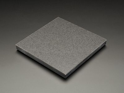
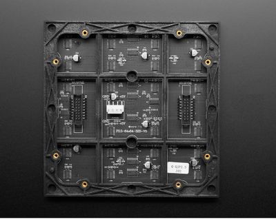
| Adafruit RGB (64x64) LED Matrix Display | $74.95 | 1 | Adafruit |
| Adafruit Analog 2-axis thumb Joystick | $10.18 | 1 | Amazon |
| 5V/4A Power Supply Adapter | $15.95 | 1 | Amazon |
| 34 Pin Flat Ribbon Cable | $6.12 | 1 | Amazon |
| PCB | $23 | 5 | PCBWay |
| DC barrel Jack | $6.70 | 1 | Amazon |
| Terminal Blocks | $8.70 | 1 | Amazon |
| Sliding Switches | $5.35 | 1 | Amazon |
Design & Implementation
Hardware Design
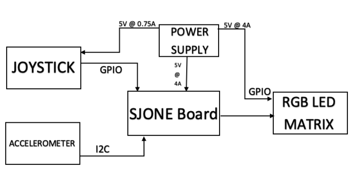
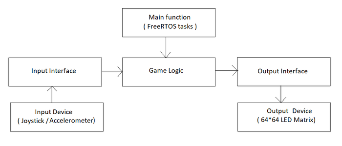
The figure below shows the basic block diagram for our game 2048 implemented on a 64x64 RGB LED matrix display.
Joystick
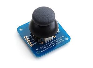
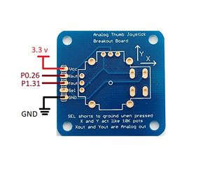
A joystick is an input device consisting of a stick that moves on a base and reports its angle or direction to the device it is controlling. In this project, we are using a joystick to give the control input. The joystick controls our game grid by moving it up, down, left and right based on the respective input fed to the microcontroller. This gives the access to the player to make the desired move and achieve the number 2048. The Joystick also has a select functionality which is nothing but a digital signal that helps the player to give a high/low signal from the joystick. In this project, we are using the Adafruit’s analog 2-axis thumb joystick (ADA512). It is an analog joystick with 2 analog pins and 1 digital pin for the select functionality. The joystick also consists of a VCC and GND pin for the power supply. The 2 analog pins give the output value corresponding to direction based on the movement of the joystick. The joystick is functional with any voltage up to 5V with 1mA current draw.
Accelerometer
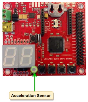
An accelerometer is an electromechanical device that will measure acceleration forces. These forces may be static, like the constant force of gravity pulling at your feet, or they could be dynamic - caused by moving or vibrating the accelerometer. We are using an accelerometer that is available on the SJOne Board just to give the player the choice of controls. The accelerometer gives the orientation of the board when it is moved in up, down, left and right directions which further controls the grid movement based on the 3-axis output value. In this project we are using the MMA8452Q is a smart low-power, three-axis, capacitive micromachined accelerometer with 12 bits of resolution. It is interfaced using the I2C digital output interface (operates to 2.25 MHz with 4.7 kΩ pull-up resistor) and works on up to 3.6V of supply voltage with 6uA – 165uA current consumption.
RGB LED Matrix
Printed Circuit Board (PCB)
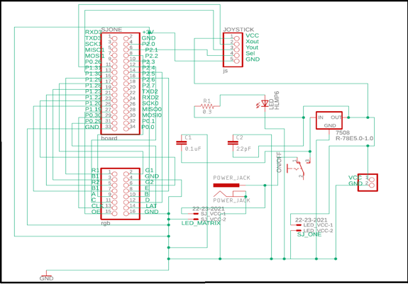
The PCB was designed using the free version of AUTODESK Eagle v9.2.0. We used the preinstalled libraries in the Eagle software and also imported Sparkfun libraries for the PCB components. The PCB constitutes the power supply circuit and all the internal connections between the devices for this project. The power supply for the joystick, SJOne Board and the RGB LED matrix display comes from this PCB. We designed a 2-layer PCB which is capable of supplying 5V output voltage at different current ratings.
PCB Schematic:
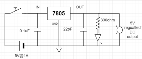
The PCB consists of a 2x17 pin header to replicate the pins of the SJOne board, it also consists of a 2x8 pin header for the RGB LED matrix display and a 5 pin header for the joystick. The circuit is controlled by the main sliding switch which gives the project an ON/OFF functionality. The circuit gets the main power supply from a 5V, 4A DC adapter which is connected to a DC barrel jack mounted on the PCB. The PCB provides the desired voltages to the SJOne board, LED display and joystick using a combination of resistors and capacitors with 7805 voltage regulator IC.
Board Layout:
EAGLE’s board designer is where the dimensions of the board come into play. The parts are arranged and connected by copper traces. In the board editor, the conceptual, idealized schematic we have designed becomes a precisely dimensioned and routed PCB.
The game logic has interface to the input and output devices. It takes direction as the input from the input device and runs move logic on the game grid. The game algorithm iterates over the 4x4 matrix of integers and merges tiles if there are two same value tiles, adjacent to each other in the direction of the input. The game score is cumulative sum of all the merges that happen in the grid. Once the game grid and scores are updated, display application is used to update the screen.
class Game {
private:
    int grid[4][4];
    int score;
    bool moved;
    DisplayApp *displayApp;   //Output Interface
    Input *input;             //Input Interface

public:
    Game(DisplayApp *displayApp, Input *gameInput);
    void updateScreen();
    void run();            //Takes direction input and calls moveTiles() and invokes updateScreen()
    void generateNewTile();
    bool moveTiles(Direction inputDirection);
    void displayScore();
    void rotate();
    void moveUp();
    void moveDown();
    void moveLeft();
    void moveRight();
    bool gridIsFull();
    bool anyPairsPresent();
    bool gameEnded();
};
Input Interface
The input for this game is just the direction. So, we can use any device that can give us the direction input. We are letting the user chose between the on-board accelerometer and a thumb joystick. In future we might also want to update the project by integrating a different input device such as touchscreen. But, adding a different device must not change anything in the Game Logic class. This idea can be implemented using an interface class, which defines the input interface. The application code for each of the input devices must implement this interface. This way game logic will only talk to the interface and not to the input device applications directly.
enum Direction {
        Still,
        Up,
        Down,
        Right,
        Left
};

class Input {
public:
    virtual Direction getDirection() = 0;
    virtual bool selectPressed() = 0;
};
Joystick Application
Joystick application implements the Input interface class. The Joystick driver gives out analog X-axis and Y-axis values when it is moved. Joystick application takes these analog values and maps them to a direction value.
class JoystickApp : public Input {
private:
    Joystick *JS;

public:
    JoystickApp(Pin pinX, Pin pinY);
    Direction getDirection();
    bool selectPressed();
    virtual ~JoystickApp();
};
Accelerometer Application
Accelerometer application implements the Input interface class. We are using the existing Accelerometer drivers from the SJOne development package. The Accelerometer driver gives out analog X-axis and Y-axis values when it is moved. The accelerometer application takes these analog values and maps them to a direction value.
class AccelerometerApp : public Input {
private:
    Acceleration_Sensor acc_sense = Acceleration_Sensor::getInstance();

public:
    AccelerometerApp() {}
    Direction getDirection();
    bool selectPressed();
    virtual ~AccelerometerApp();
};
Joystick Driver
Thumb Joystick is an analog device. It gives the analog X-axis and Y-axis values whenever it is moved. So, input from joystick is read through the ADC channels of lpc1758. We are using the existing ADC driver available in our SJOne development package and building the joystick driver on top of it. Select signal in the Joystick is currently not being used.
enum Pin {
        k0_25,       // AD0.2 <-- Light Sensor -->
        k0_26,       // AD0.3
        k1_30,       // AD0.4
        k1_31,       // AD0.5
};

class Joystick {
private:
    uint8_t channelX, channelY;

public:
    Joystick(Pin pinX, Pin pinY);
    void selectPin(Pin pin);
    uint8_t getChannelNumberOfPin(Pin pin);
    uint16_t getX();
    uint16_t getY();
};
FreeRTOS Tasks
The entire application being very simple, does not need too many tasks. The game grid is updated only when there is any input from the user. So, there must be a task that can sample the input at regular intervals and run the game algorithm based on the input. Display has to be updated very frequently for the output to seem stable on the display. We could use either a Repetitive Software Interrupt or a task that runs at right frequency. We have chosen to use a task for updating display since an interrupt based design would be less predictable.
The main code initiates the display and takes user selection of input device. It then creates tasks to start the game.
displayApp.initDisplay(displayPincon);
xTaskCreate(displayTask, "Display", STACK_SIZE, 0, PRIORITY_HIGH, NULL);
xTaskCreate(gameLogicTask, "Game", STACK_SIZE, 0, PRIORITY_MEDIUM, NULL);

void displayTask(void *p)
{
    while(1) {
        displayApp.updateDisplay();
        vTaskDelay(7);
    }
}

void gameLogicTask(void *p)
{
    game.generateNewTile();
    game.generateNewTile();
    while(1) {
        game.run();
        vTaskDelay(150);
    }
}
Testing & Technical Challenges
Testing
Challenges
The challenges in the implementation of this project were as follows.
- Understanding LED Matrix Display
Include sub-sections that list out a problem and solution, such as:
<Bug/issue name>
Discuss the issue and resolution.
Conclusion
Conclude your project here. You can recap your testing and problems. You should address the "so what" part here to indicate what you ultimately learnt from this project. How has this project increased your knowledge?
Project Video
Upload a video of your project and post the link here.
Project Source Code
References
Acknowledgement
Any acknowledgement that you may wish to provide can be included here.
References Used
List any references used in project.
Appendix
You can list the references you used.
Philosophy
Following are some philosophical renditions of the concepts we have learned in this wonderful class. This is partly inspired by The Zen of Python and mostly by our constant quest for knowledge.
- Priorities are very important; set them correctly.
