Difference between revisions of "S18: Hand gesture controlled multiplayer game"
Proj user10 (talk | contribs) (→Hardware Design) |
Proj user10 (talk | contribs) (→Hardware Design) |
||
| Line 207: | Line 207: | ||
=== Hardware Design === | === Hardware Design === | ||
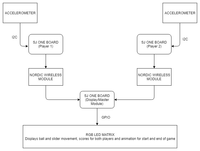
| − | [[File:CmpE244_S18_System_Block_Diagram.jpg| | + | [[File:CmpE244_S18_System_Block_Diagram.jpg|800px|thumb|center|System block diagram]] |
=== Accelerometer Sensor=== | === Accelerometer Sensor=== | ||
Revision as of 06:41, 10 May 2018
Contents
Grading Criteria
- How well is Software & Hardware Design described?
- How well can this report be used to reproduce this project?
- Code Quality
- Overall Report Quality:
- Software Block Diagrams
- Hardware Block Diagrams
- Schematic Quality
- Quality of technical challenges and solutions adopted.
Project Title
Hand gesture controlled multiplayer game
Abstract
This project involves implementation of a wireless and hand-gesture controlled multiplayer ping pong (2D) game using the Adafruit's 16x32 RGB LED Matrix. It incorporates the on-board RF Nordic wireless transceiver for wireless communication and the on-board acceleration sensor to translate the hand movement into the slider movement on the display.
Objectives & Introduction
Show list of your objectives. This section includes the high level details of your project. You can write about the various sensors or peripherals you used to get your project completed.
Team Members & Responsibilities
- Akil Khan
- Design and development of the RGB Led Matrix driver
- Game logic development, implementation, QA and testing.
- Abhilash Tuse
- Game logic development
- Logic Development for communication between hand gesture control board and controller board
- Disha Patil
- Design of PCB using Eagle for Power Supply
- Hand gesture control logic development using accelerometer
- Omkar Kale
- Hand gesture control logic development using accelerometer
- Logic Development for communication between hand gesture control board and controller board
- Vishal Shrivastava
- Design and development of the RGB Led Matrix driver
- Design of PCB using Eagle for Power Supply
Schedule
Show a simple table or figures that show your scheduled as planned before you started working on the project. Then in another table column, write down the actual schedule so that readers can see the planned vs. actual goals. The point of the schedule is for readers to assess how to pace themselves if they are doing a similar project.
| Week# | Date | Task | Status | Actual Completion Date |
|---|---|---|---|---|
| 1 | 10/04/2018 |
|
|
|
| 2 | 17/04/2018 |
|
|
|
| 3 | 24/04/2018 |
|
|
|
| 4 | 01/05/2018 |
|
|
|
| 5 | 08/05/2018 |
|
|
|
| 6 | 15/05/2018 |
|
|
|
Parts List & Cost
| Item# | Part | Manufacturer | Part number | Quantity | Cost($) |
|---|---|---|---|---|---|
| 1 | SJ One Board | Preet | 3 | 80.00 | |
| 2 | Adafruit RGB LED Matrix | LED Matrix | 1 | 35.00 | |
| 3 | Power Adapter | Power Supply | 1 | 7.95 | |
| 4 | Power Bank 800mah | Aibocn | 2 | 11.95 | |
| 5 | PCB Board | ||||
| 6 | Hardware | Excess Solution | Barrel Jack, Jumper wires, Connectors | 5.00 |
- Total Cost:306.955$
Design & Implementation
The design section can go over your hardware and software design. Organize this section using sub-sections that go over your design and implementation.
Hardware Design
Accelerometer Sensor
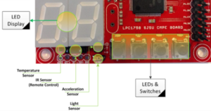
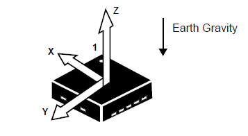
The SJOne board has an accelerometer which is interfaced on the I2C2 bus. Accelerometers are electromechanical devices that sense either static or dynamic forces of acceleration. Static forces include gravity, while dynamic forces can include vibrations and movement.The measurements are on 3-axis and these values can be calibrated to find the desired values.
In our project, accelerometer is used for detecting the up-down movement of the wrist. We are using accelerometers on two SJ-One Boards for gesture recognition. The movement from accelerometer sensor will be used to control the slider movement on the RGB LED Matrix.
Wireless Module
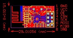
Nordic wireless chip nRF24L01+ is interfaced with SJone board using SPI bus protocol.
Hardware Interface Diagram
In this section, you can describe how your hardware communicates, such as which BUSes used. You can discuss your driver implementation here, such that the Software Design section is isolated to talk about high level workings rather than inner working of your project.
Software Design
Show your software design. For example, if you are designing an MP3 Player, show the tasks that you are using, and what they are doing at a high level. Do not show the details of the code. For example, do not show exact code, but you may show psuedocode and fragments of code. Keep in mind that you are showing DESIGN of your software, not the inner workings of it.
Implementation
This section includes implementation, but again, not the details, just the high level. For example, you can list the steps it takes to communicate over a sensor, or the steps needed to write a page of memory onto SPI Flash. You can include sub-sections for each of your component implementation.
Testing & Technical Challenges
Describe the challenges of your project. What advise would you give yourself or someone else if your project can be started from scratch again? Make a smooth transition to testing section and described what it took to test your project.
Include sub-sections that list out a problem and solution, such as:
<Bug/issue name>
Discuss the issue and resolution.
Conclusion
Conclude your project here. You can recap your testing and problems. You should address the "so what" part here to indicate what you ultimately learnt from this project. How has this project increased your knowledge?
Project Video
Upload a video of your project and post the link here.
Project Source Code
References
Acknowledgement
We would like to thank our Professor Preetpal Kang for all his teachings and inspirational lectures. Not only did we enjoy working though out this project but also gave us an overall learning experience and precious life lessons. We would also like to thank the ISA members for always being ready to help with whatever issues we faced.
References Used
[1] FreeRTOS documentations [2] Adafruit LCD library [3] CMPE 244 Lecture notes from Preetpal Kang, Computer Engineering, San Jose State University. Feb - May 2018.


