Difference between revisions of "F17: Viserion"
Proj user7 (talk | contribs) (→Soft Iron Effect for Compass) |
Proj user7 (talk | contribs) m (→Servo) |
||
| Line 511: | Line 511: | ||
|- | |- | ||
! scope="col"| Pin No. (SJOne Board) | ! scope="col"| Pin No. (SJOne Board) | ||
| − | ! scope="col"| | + | ! scope="col"| Description |
! scope="col"| Wire Color Code | ! scope="col"| Wire Color Code | ||
|- | |- | ||
| − | ! scope="row"| P2. | + | ! scope="row"| P2.1 |
| PWM Signal | | PWM Signal | ||
| WHITE | | WHITE | ||
|- | |- | ||
! scope="row"| VCC | ! scope="row"| VCC | ||
| − | | | + | | 5V |
| RED | | RED | ||
|- | |- | ||
! scope="row"| GND | ! scope="row"| GND | ||
| − | | | + | | Ground |
| BLACK | | BLACK | ||
|- | |- | ||
| Line 531: | Line 531: | ||
<br> | <br> | ||
<br> | <br> | ||
| + | |||
==== RPM Sensor ==== | ==== RPM Sensor ==== | ||
[[File:CmpE243_F17_Viserion_RPMSensor.JPG|300x300px|thumb|right|Traxxas RPM Sensor]] | [[File:CmpE243_F17_Viserion_RPMSensor.JPG|300x300px|thumb|right|Traxxas RPM Sensor]] | ||
Revision as of 09:44, 19 December 2017
Contents
- 1 Viserion Team RC Car
- 2 Abstract
- 3 Objectives & Introduction
- 4 Schedule
- 5 Parts List & Cost
- 6 Process Control
- 7 PCB Design
- 8 Sensors Controller
- 9 Motor and I/O Controller
- 10 Master Controller
- 11 Bluetooth Controller And Android Application
- 12 Geographical Controller
- 13 $GPGGA,HHMMSS.SS,DDMM.MMMMM,K,DDDMM.MMMMM,L,N,QQ,PP.P,AAAA.AA,M,±XX.XX,M,SSS,RRRR*CC<CR><LF>
- 14 Testing & Technical Challenges
- 15 Conclusion
- 16 References
Viserion Team RC Car
Abstract
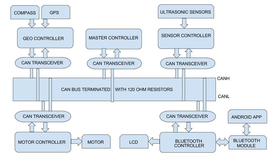
Aim of this project is to build a self-navigating car. The car is divided into five modules. Each module consists of SJ One board as the main controller. The different modules in the car are master, sensors, geo, motor and bluetooth module. The car uses CAN communication protocol for communication between the modules.
The five modules of the car are :
Sensor Controller: This module detects obstacles in the driving path with the help of ultrasonic sensors.
Motor Controller: This controller drives the DC motor and Servo in the car.
Geographical Controller: This module assists the car in navigating to a destination with the help of location details provided by GPS and the orientation(bearing and heading angle) provided by the compass.
Bluetooth Controller: The controller uses Bluetooth to communicate with an Android application. Destination coordinates are provided by this module. The bluetooth module also displays important data like sensor readings, GPS coordinates and speed.
Master Controller: This module will collect data from all modules and direct the motor towards the destination.
Objectives & Introduction
Objectives
The objectives are as follows:
1.To detect and avoid obstacles encountered in the path.
2.To move at an appropriate speed depending upon the path requirement.
3.To use Bluetooth module to start/stop the car and display important data on the LCD.
4.To integrate gps and compass to make sure that the car navigates from source to destination.
5.To efficiently establish communication between all the modules using CAN protocol.
6.To reach a destination given by the Bluetooth module autonomously for a valid path.
System Block Diagram
Team Members & Responsibilities
Master Controller
- Aakash Menon
- Omkar Kale
Geographical Controller
- Ajinkya Mandhre
- Aniket Dali
- Jean Madassery
Sensor Controller
MOTOR & I/O CONTROLLER
- Manoj Ramesh Rao
- Pratap Ramachandran
BLUETOOTH CONTROLLER & ANDROID APP
- Dheemanth Bangalore Vishwanatha
- Pratap Kishore Desai
Schedule
Show a simple table or figures that show your scheduled as planned before you started working on the project. Then in another table column, write down the actual schedule so that readers can see the planned vs. actual goals. The point of the schedule is for readers to assess how to pace themselves if they are doing a similar project.
Legend: Motor & I/O Controller , Master Controller , Communication Bridge Controller, Geographical Controller, Sensor Controller , Team Goal , Team PCB, , Team Android
| Week# | Start Date | End Date | Task | Actual Completion Date / Notes | Status |
|---|---|---|---|---|---|
| 1 | 10/09/2017 | 10/15/2017 |
|
Done | |
| 2 | 10/16/2017 | 10/22/2017 |
|
Done on time except
|
|
| 3 | 10/23/2017 | 29/10/2017 |
|
Done on time except
|
|
| 4 | 10/30/2017 | 11/05/2017 |
|
Done on time | |
| 5 | 11/06/2017 | 11/12/2017 |
|
|
|
| 6 | 11/13/2017 | 11/19/2017 |
|
|
|
| 7 | 11/20/2017 | 11/25/2017 |
|
|
|
| 8 | 11/26/2017 | 12/01/2017 |
|
|
|
| 9 | 12/03/2017 | 12/08/2017 |
|
||
| 10 | 12/10/2017 | 12/12/2017 |
|
||
| 11 | 12/13/2017 | 12/16/2017 |
|
||
| 12 | 12/17/2017 | 12/19/2017 |
|
||
| 13 | 12/20/2017 |
|
Parts List & Cost
| Item# | Part Desciption | Vendor | Qty | Cost |
|---|---|---|---|---|
| 1 | RC Car - Traxxas 1/10 Slash 2WD | Amazon | 1 | $189.95 |
| 2 | Battery - Traxxas 7600mAh 7.4V 2-Cell 25C LiPo Battery | Amazon | 2 | $143.26 |
| 3 | Charger - Traxxas 2970 EZ-Peak Plus 4-Amp NiMH/LiPo Fast Charger | Amazon | 1 | $49.95 |
| 4 | GPS - Readytosky Ublox NEO-M8N GPS Module | Amazon | 1 | $29.98 |
| 5 | Bluetooth Module HC-05 | Amazon | 1 | $8.99 |
| 6 | IMU SparkFun 9DoF Razor IMU M0 | SparkFun | 1 | $49.95 |
| 7 | LV Maxsonar EZ0 Ultrasonic sensors | Robotshop | 6 | $158.7 |
| 8 | RPM Sensor - Traxxas 6520 RPM Sensor | Amazon | 1 | $10.25 |
| 9 | Jumper Wires | Amazon | 1 | $10 |
| 10 | Acrylic Board MIFFLIN Acrylic Plexiglass 12 x 12 | Amazon | 1 | $11 |
| 11 | CAN tranceivers | Microchip Samples | 30 | Free |
| 12 | SJOne Boards | Provided by Preet | 5 | $400.0 |
Process Control
Progress Tracking
- For efficient progress tracking purposes, we exclusively created Milestones in GIT project repository and assigned tasks to the respective module owners.
- Milestones divided into smaller tasks and assigned to the module members.
- The task assignee had to regularly update the tasks with the impediments and useful information.
- Once the task was completed, it was dragged forward from "doing" stage to "closed" stage on the task board. In this way we were able to keep regular track on the completed and pending tasks.
Unit Testing
Code review
- During the planning phase of the project we had listed a set of coding guidelines to be followed uniformly within the team. This included naming
conventions, code commenting formats, committing formats etc. For example: The whole team followed the below rule while committing the code:
Git commit – m “Modulename_Personsinitial: short description of what was added”
 Ex: if ABC wants to make a commit to GEO module ABC would:
 Git commit –m “GC_ABC: Added new file for XYZ”
- After the code has been pushed by a module member onto GIT, all the respective module members would meet up in the presence of 1 or 2 external module member and brainstorm on the written code to find code bugs, cosmetic errors, logical errors etc. The team member would then fix the bugs and push the final code.
PCB Design
Sensors Controller
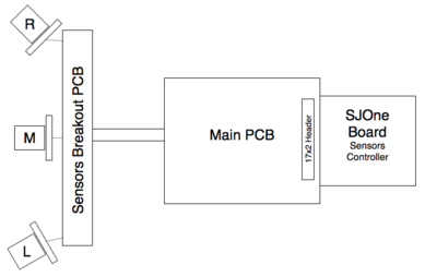
Based on research done on previous projects we decided to use Maxbotix EZ0 Ultrasonic sensors due to its reliability and cost. Four sensors total are used in this project. Three front sensors and one back sensor. They are all of the same type and manufacturer. Since they are triggered at different time, every 50ms, there was no need to use different sensor with different ranging frequency.
Hardware Design
There are two PCBs on car that are involved in wiring sensors, providing them with power and collecting data from them. “Main PCB” which is directly connected to Sensor Controller and “Sensors breakout PCB” which is mounted at the front of the car as close to sensors as possible to reduce wire length that goes through air. Two PCBs are connected with 12-pin ribbon cable. The sensors are powered with 3.3V and since we had only 5V power from power bank, we had to use 3.3V voltage regulator mounted on “Sensors breakout PCB”. Providing stable input voltage for sensors was also required because of unstable reading we were getting from sensors, caused by electrical interference. Our front sensors were interfaced by ADC, so stable input voltage was a must. Back sensor was interfaced by PWM since SJOne board has only three ADC pins.
3D Printing Design
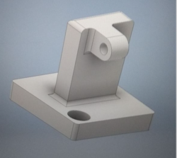
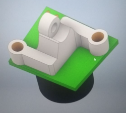
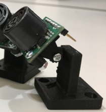
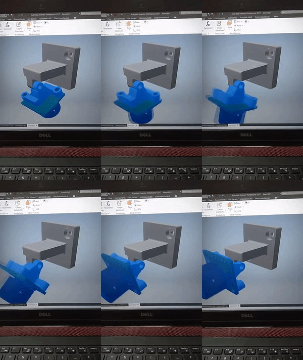
As a really important part of hardware design, 3D printing part was fun to make. After testing sensors on different heights from the ground and different angles we noticed that best results are when sensors are mounted as closer to the ground as possible, so we came out with our own design for sensors mount. Most important thing to consider when making design was to be able to adjust tilt of the sensors since we were receiving lot of reflection from the ground with temporarly mounts we used until we got the final printed version. So in order to satisfy that requirement mount is constructed from two parts, the stand and part that holds the sensor what gave us freedom to test sensors positioning during testing phase.
Hardware Interface
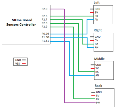
Sensors are interfaced with combination of GPIO, ADC and PWM pins. GPIO pins are used to trigger all sensors. Three ADC pins collect output from front sensors and PWM pin collect output from back sensor. Below you can see pin layout and schematics.
|
Software Design
Show your software design. For example, if you are designing an MP3 Player, show the tasks that you are using, and what they are doing at a high level. Do not show the details of the code. For example, do not show exact code, but you may show pseudocode and fragments of code. Keep in mind that you are showing DESIGN of your software, not the inner workings of it.
Implementation
This section includes implementation, but again, not the details, just the high level. For example, you can list the steps it takes to communicate over a sensor, or the steps needed to write a page of memory onto SPI Flash. You can include sub-sections for each of your component implementation.
Motor and I/O Controller
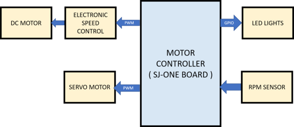
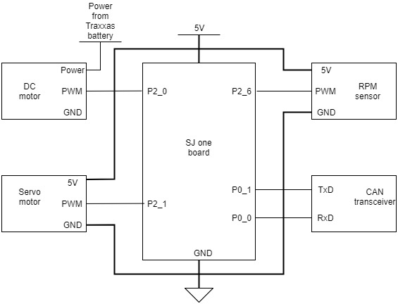
The motor controller is responsible for the steering and controlling the speed of the car. Both direction and speed of the car is controlled using the duty cycle of PWM signal. The RC car comes with a DC motor for driving the car and a servo motor for steering the vehicle. The speed of the car can also be controlled using the Electronic Speed Controller(ESC), which drives the motor based on the PWM signal. Additionally, a RPM sensor was mounted inside the DC motor bracket, to control the speed of the car based on this feedback.These modules where interfaced such that it can work solely on the command from the Master Controller. These modules are explained in further detail in the hardware interface section below.
Design and Implementation
For controlling both the DC motor and Servo motor using the SJ-one board, we require to transmit the required duty cycle. Initially the Radio Control remote provided by Traxxas was used to determine the duty cycle for speed and direction by probing it to using a Oscilloscope. Hence, based on our requirements for steering five different PWM duty cycles were captured for center, slight left, left , right and slight right positions. Before implementing speed control based on feedback, ideal speed for testing was chosen and corresponding PWM cycle was captured.
After mounting the RPM sensor, the rotations per second(rps) could be calculated as it generated a signal for every rotation of the motor shaft. Using this signal as interrupt, the rps was calculated in the 1Hz periodic function. Based on the rps value calculated every second the PWM signal sent to drive the DC motor was calculated dynamically to achieve the required rps specified by the Master controller.
Hardware Design
The hardware design includes the servo motor, DC motor, ESC and the SJ-one board. Both the ESC and Servo motor are connected to PWM pins on the SJ-one board for sending PWM signals to steer and drive the vehicle. The ESC is used to control the DC motor of the car.The power source for both ESC and DC motor is a LiPo battery. The servo motor, RPM sensor and other LEDs are powered using 5v from a power bank.
Hardware Interface
DC Motor
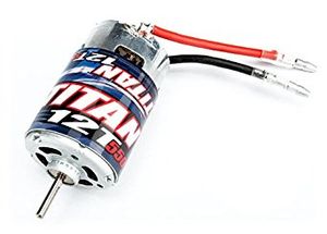
The DC motor is used to drive the vehicle using PWM signal transmitted to ESC. The DC motor in the car is provided by Traxxas and is a 12-turn brush-less motor. It can be considered as the most important part of the vehicle as it drives the vehicle ahead. The motor can be driven either in the forward direction or reverse by setting appropriate duty cycle to the ESC. In order to achieve reverse direction, the motor has to cycle through states of neutral at least once before going into reverse.
| Wires on (ESC) | Description | Wire Color Code |
|---|---|---|
| (+)ve | Positive Terminal | RED |
| (-)ve | Negetive terminal | BLACK |
ESC
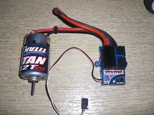
The Electronic Speed Controller is also powered on by the LiPo battery and is used to control the DC motor based on the PWM signals sent to the ESC. In the figure below it can be seen that the ESC has three color coded wires which serve as pins for PWM signal(WHITE Color), VCC(RED Color) and GND(BLACK Color).
The ESC comes with the feature of calibrating the DC motor using the EZ set button that is present. It comes with three modes namely Training mode, racing mode and Sport mode and also with low voltage detection. For our project we initially used the training mode and then shifted to the Sport mode because we needed full capability of the motor for uphills and rough terrains.
| ESC wires | Description | Wire Color Code |
|---|---|---|
| P2.0 | PWM Signal From SJOne | WHITE |
| Vcc | Not Required | RED |
| Ground | Negative terminal | BLACK |
Servo
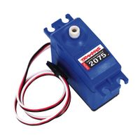
The servo motor is used to steer the vehicle based on commands received from the master controller. The servo motor is powered on using 5V power supply via PCB from the power-bank. The servo motor also has three pins which serve as pins for PWM signal(WHITE Color), VCC(RED Color) and GND(BLACK Color). The PWM pin configured to supply steering signal on the SJ-one board is connected to the PWM pin on the servo. We have used PWM signals at 120Hz, the values were sent for the five different positions as per the Master controller commands.
| Pin No. (SJOne Board) | Description | Wire Color Code |
|---|---|---|
| P2.1 | PWM Signal | WHITE |
| VCC | 5V | RED |
| GND | Ground | BLACK |
RPM Sensor
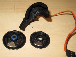
The RPM sensor is used to measure the RPS of the shaft attached to DC motor. The sensor consists of magnet and a signal is generated every time the motor shaft cuts the magnet. This signal is used received as an interrupt on a GPIO pin in the SJ-one board. By using this, the rotations per second is calculated by clearing the interrupt every one second in the 1Hz periodic function. The sensor is installed in the gear compartment of the Traxxas car along with the magnet trigger. The pulse gets generated every time the wheel roattes and is sent on the white wire. The other two wires are used for 5V power Supply (Red) and Ground(Black).
| Pin No. (SJOne Board) | Function | Wire Color Code |
|---|---|---|
| P2.6 | GPIO (INPUT) | WHITE |
| VCC | 5 Volts | RED |
| GND | 0 volts | BLACK |
Software Design
Software design for the motor controller consist of different software modules that control speed, steering, inputs and outputs interface using touch screen LCD, and sensing the speed of the car. Controlling speed, steering and sensing speed is done using 10Hz periodic loop. On the other hand the code for LCD input and output run as a task that get scheduled in between the 10Hz periodic scheduler.
The second phase of the motor controlling is maintaining a constant speed i,e., to find out the speed at which it is running and control the car based on the speed at which it is traveling. This comes in handy when the car has a destination that goes uphill. This operation can be called as speed controlling. This operation is done with the help of a speed sensor that can be fixed either on to the wheel or on to the transmission box of the car.
Steering Control
Speed Control
Consistent speed based on feedback
The design section can go over your hardware and software design. Organize this section using sub-sections that go over your design and implementation.
Implementation
This section includes implementation, but again, not the details, just the high level. For example, you can list the steps it takes to communicate over a sensor, or the steps needed to write a page of memory onto SPI Flash. You can include sub-sections for each of your component implementation.
Master Controller
The master controller is the brain of the car. It communicates over CAN bus with other modules to receive data. It accepts the values of different sensors mounted in front and rear, and takes decision based on this data. It uses heartbeat mechanisms to keep a check on other modules in the system. The entire module has two main algorithms : one for Obstacle Avoidance and another for Navigation.
Hardware Design
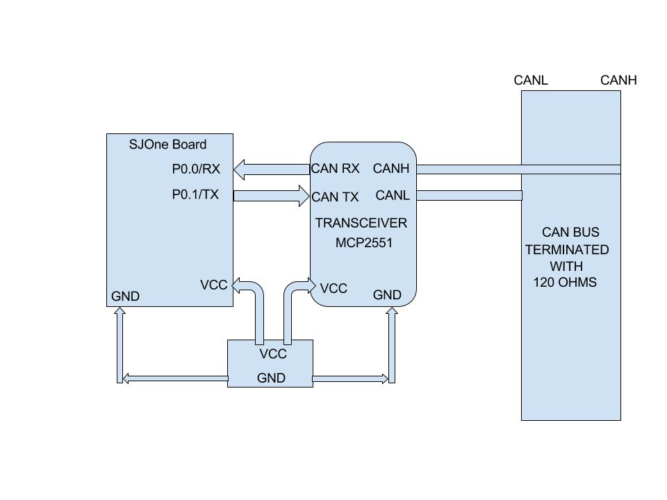
This module was interfaced with Microchip CAN transceiver MCP2551 to communicate with other nodes in the bus. No external peripherals were connected to the master controller.
The figure below shows the hardware design of the master.
Software Design
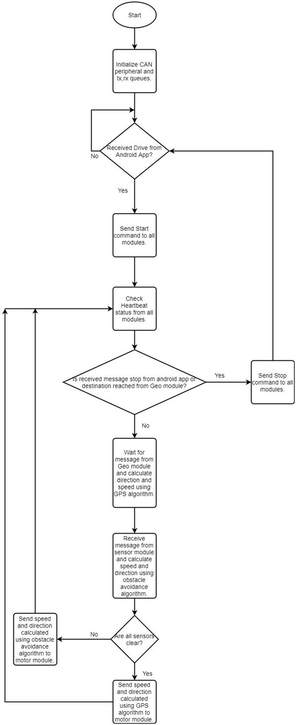
Main flow of Master controller
Master Controller uses 100Hz periodic task to receive values from other controllers. Using 100Hz periodic function ensures that most of the messages are received reliably.We have used 1 Hz task to check whether the CAN bus is working or not.
Obstacle Avoidance
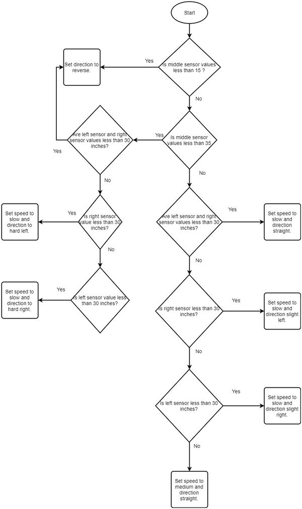
For obstacle avoidance, priority was given to the middle sensor. The values obtained from middle sensor were checked first and then various conditions were applied to check the values of the left and right sensor.
The flowchart below shows the obstacle avoidance algorithm.
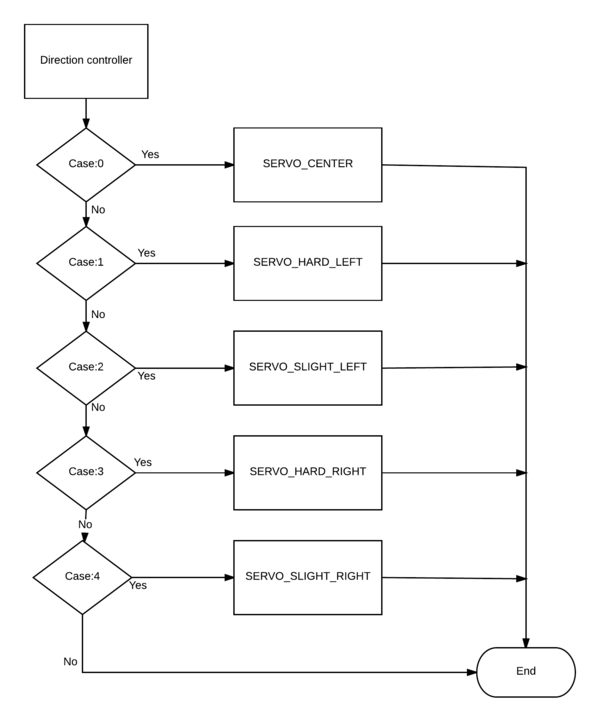
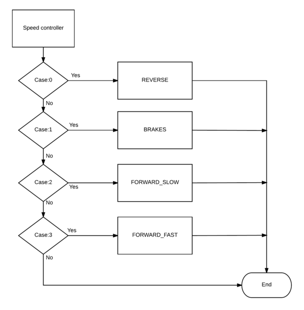
We used two enums to represent the various speeds and directions we would be sending to the motor module.The following snippet shows the enums we used. Such enums make the code readable and easily understandable.
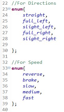
Directions And Steering Signals
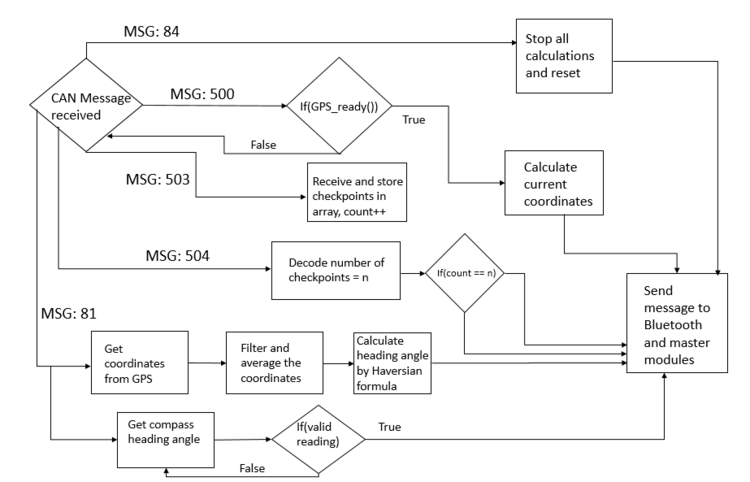
The compass readings gave a heading angle between 0 and 360. The bearing angle was obtained from the GPS module. The difference between this values would give us the direction in which the car should head if there is no obstacle.
The flowchart below shows the navigation algorithm.
Implementation
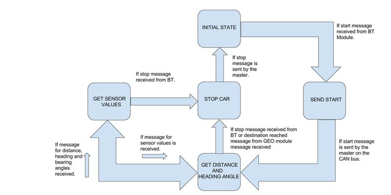
The master has to coordinate with other nodes and take decisions. To achieve this, we have used a state machine. The master takes specific decisions depending upon the state in which the car is. We have used five states : initial state, send start, get distance and heading angle, get sensor values and stop car state.
Initial State: The car will not move till all the initialization is done. The car will wait till it receives a start signal from bluetooth module.
Send Start State: In this state, the master will send a start signal to all the modules and wait till this message is transmitted over the CAN bus.
Get Distance and Heading Angle State: The master receives the heading,bearing angles and the direction from the geo module and then switches to other state.
Get Sensor Values State: The master will check for sensor values. Once it receives the values, master has to make a decision either to avoid obstacle or to go in the direction of the checkpoint.The master will go from 'get sensor values state' and 'get distance and heading angle state' till it reaches the destination or in other words, it reaches the stop state.
Stop Car State: The car goes to this state when it receives stop signal from bluetooth module or when it receives Destination reached message from the Geo module. In this state, the master will send a stop car signal to all the other modules.Once the stop signal is sent, the car will go back to initial state where it will wait for start message from the bluetooth module.
Bluetooth Controller And Android Application
Design And Implementation
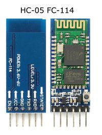
The user selects a destination on the android application which then communicates with the Bluetooth module HC-05 through which car gets to know the route to destination. The user can directly interact with the car using the android application so this is one of the most important modules. The detailed software and hardware design is mentioned in below sub sections.
Hardware Design
This includes
• SJ-One Board
• Bluetooth Module HC-05
• Android Smartphone
• CAN transceiver
Bluetooth And SJOne Board Connection Diagram
Bluetooth Module
Specifications
• Bluetooth protocol: Bluetooth Specification v2.0+EDR
• Frequency: 2.4GHz ISM band
• Speed: Asynchronous: 2.1Mbps(Max) / 160 kbps, Synchronous: 1Mbps/1Mbps
• Profiles: Bluetooth serial port
• Power supply: +3.3VDC 50mA
• Working temperature: -20 ~ +75Centigrade
• Dimension: 26.9mm x 13mm x 2.2 mm
• Modulation: GFSK(Gaussian Frequency Shift Keying)
• Sensitivity: ≤-84dBm at 0.1% BER
• Security: Authentication and encryption
Hardware Interface
The Bluetooth module HC05 is connected to Bluetooth-ECU using UART3. The transmission rate is 9600bps. Bluetooth-ECU communicates with all other ECU's using CAN-Transceiver.The following pins where used for connections.
Bluetooth-ECU
| Function On ECU | Pin NO On ECU | Function On HC05 |
|---|---|---|
| RX | P4_28 | TX |
| TX | P4_29 | RX |
Software Design
Bluetooth Module
|
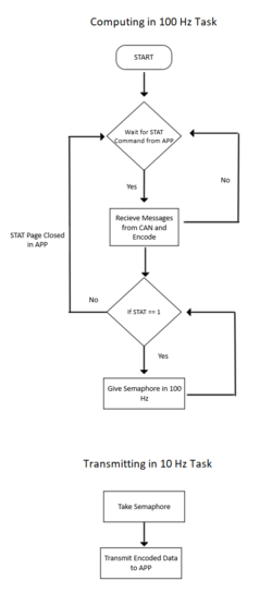
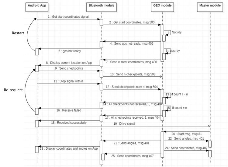
The Bluetooth module establishes communication between the car and the user. Here there is a need for simultaneous communication between other modules and the android application. To achieve this with ease we distributed the data processing and transmission.
|
Android Application
Implementation
Testing
Technical Challenges
Geographical Controller
Design And Implementation
The Geographical controller acts as the navigation unit for the Viserion. It communicates with the attached GPS and compass unit over UART interfaces. It determines the location of the car in terms of Latitude and Longitude and figures out the car's direction with respect to Magnetic North axis. The Geo controller sends the Car's current location to BT application and then receives the source to destination check points, back from the BT application. Geo module periodically calculates the bearing angle with respect to the destination (subsequent checkpoints) and it sends the bearing angle and the compass angle to master module to steer the car towards the destination.
Hardware Design
The components included in Geo Module are as follows
• SJ-One Board
• GPS Module
• Compass Module
• CAN transceiver
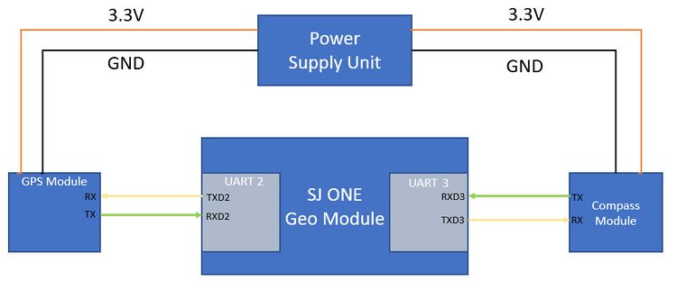
The following block diagram captures how the GPS and Compass modules are interfaced with Geographical Controller.
Software Design
Components
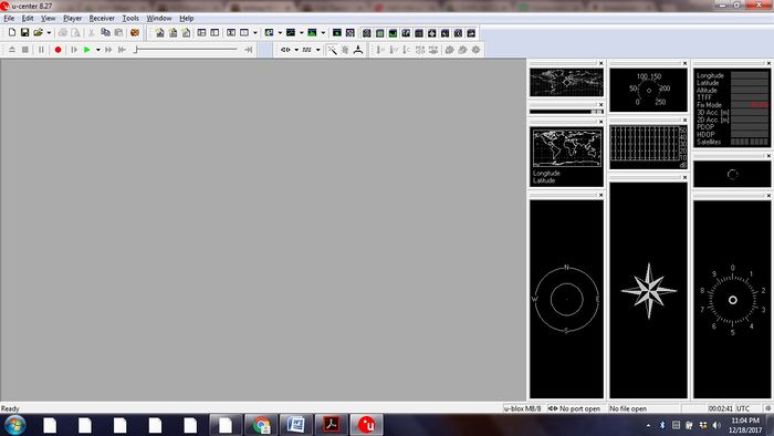
Accuracy of Compass and GPS module is of paramount importance, to successfully navigate the car towards the destination. The compass module is sensitive to the magnetic interference generated from the other components on the car and thus needs to be calibrated to compensate those interfaces. GPS module offers different configuration such as baud rate, selection of positioning systems etc, The module needs to be configured using u-center application from UBlocks.
Compass Module
The Sparkfun's SEN-14001 9DOF Razor's MPU-9250 module has ability to detect linear acceleration, angular rotation velocity and magnetic field vectors using on board 3 axis sensors such as accelerometer, gyroscope and magnetometer.
Compass Calibration
The Calibration of compass module is done with the help of Arduino IDE and the Magnetometer script written using open GL framework "processing".
The Guide https://learn.sparkfun.com/tutorials/9dof-razor-imu-m0-hookup-guide
from Sparkfun walks through the steps required to setup the environment to communicate with the compass module.
We followed the following procedure to calibrate the compass module.
Note the procedure mention is with respect to the east coast, it will differ sligtly for west coast
1. Download and flash the application written by "elizabethsrobert" to output the maximum and minimum values from all the three sensors.
The firmware can be obtained from the following link
https://github.com/sparkfun/9DOF_Razor_IMU
2.Calibrating accelerometer
To calibrate the accelerometer, tune the calibration application to output the maximum and minimum readings for all the three axes from accelerometer. To calibrate X axis,Hold the accelerometer flat to the surface and rotate it along Y-axis such to get the Xmax and Xmin value.
Be careful to move the accelerometer slowly so that it is not affected by the acceleration of gravity. Repeat the sequence for all the axes.
3.Calibrating Gyroscope
Keep the module stable on the surface, select the gyroscope calibration, the module will average out noise on all the axes.
4.Calibrating Magnetometer [Hard Iron effects]
Align the X-axis of the magnetometer with North pole of the earth and rotate the module along E-W axis, tilt the compass in little further in both the axes until you the max/min values are increasing. Repeat the step for all the other axes.
5.Magnetic declination
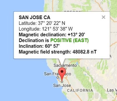
The true magnetic north pole is deviated by +13.22 degrees as of December 18,2017, consider the declination values to calibrate the compass.
The following Picture shows the magnetic declination at sanjose. Magnetic Declination Calculator http://www.magnetic-declination.com
6. Feed all the calculated values back to the application written by "elizabethsrobert to output the calibrated pitch,roll,yaw values. The Yaw value points to the Y axis of Magneto meter which provides the Head angle of compass with respect to the magnetic north.
GPS Module
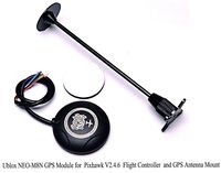
The GPS module is the core unit of the car that is responsible to accurately navigate the car to it's destination based on the Latitude and Longitude values it provide. Choosing the right, stable and a good GPS module is crucial for the car's ultimate working. If the GPS used is of cheap quality then there are lot's of trouble in it's calibration and navigation. Investing in a right GPS module is the most important thing for the team and car's functioning. After a lot of study and understanding the previous projects we decided to select the Ublox GPS chip[1]There are some modules available that have incorporated the Ublox GPS chip and created a product that can be directly used by the user in their system with minimum technical challenges. We also decided to go with one such module. Readytosky Ublox NEO-M8N GPS Module w/ Built-in HMC5883L Compass Protective Case with GPS Antenna Mount[2]
Why we selected Ublox GPS module?
The very first reason is the quality and technical support provided by the Ublox. Also the Ublox module was available on Amazon at a fairly good price. Having a good review on internet across various websites, it was seen that this module found its application use in many projects including quad copters and drones. This significantly shows that how stable, good and reliable the module is.
Some of the technical features of the module are:
The NEO-M8 series utilizes concurrent reception of up to three GNSS systems (GPS/Galileo together with BeiDou or GLONASS), recognizes multiple constellations simultaneously and provides outstanding positioning accuracy in scenarios where urban canyon or weak signals are involved. For even better and faster positioning improvement, the NEO-M8 series supports augmentation of QZSS, GAGAN and IMES together with WAAS, EGNOS, MSAS. The NEO-M8 series also supports message integrity protection, geofencing, and spoofing detection with configurable interface settings to easily fit to customer applications. The NEO form factor allows easy migration from previous NEO generations. The NEO-M8M is optimized for cost sensitive applications, while NEO-M8N/M8Q provides best performance and easier RF integration. The NEO-M8N offers high performance also at low power consumption levels. The future-proof NEO-M8N includes an internal Flash that allows future firmware updates. This makes NEO-M8N perfectly suited to industrial and automotive applications.
Support for the GPS module:
Apart from this the Ublox provides user with a Software frame work called the U-center. u-center evaluation software provides system integrators and end users with a quick and simple way to interface with u-blox GNSS chipsets, modules and boards. It enables easy evaluation, performance testing, development and debugging of GNSS positioning chips and modules. u-center allows easy connection to u-blox products and provides a suite of features to view, log, and analyze performance.
GPS Calibration
The GPS module that is received from the vendor is not calibrated or configured. Directly using the module in the car would result in lot of technical challenges and problems. We first need to understand our application use case and then configure and calibrate the GPS as per our requirement.
Now what exactly are we looking in terms of configuration/calibration for the GPS module?
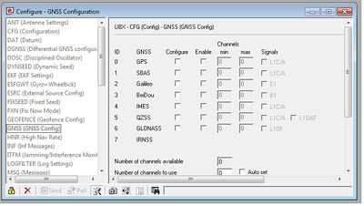
The GPS module by default has multiple GNSS (GPS, Galileo, GLONASS and BeiDou) constellations active. Also there are other Augmentation systems(SBAS, QZSS, IMES, D-GPS) that are active. There are different NMEA protocol (GPGGA, GLL, GSV, GST, RMC, etc) messages that are simultaneously received as well. The baud rate is at different speed (9600 default) for the UART communication.
To have the GPS module perfectly work for the autonomous car requirement we had to do many configurations including.
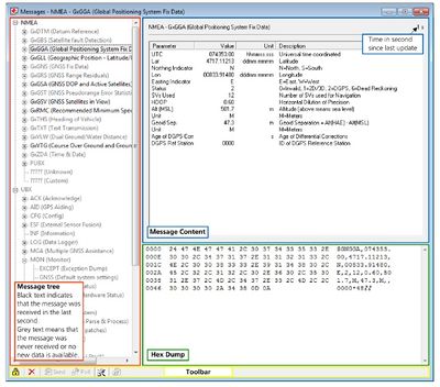
1-Setting the NMEA messages to GPGGA format
2-Increasing the baud rate to 115200
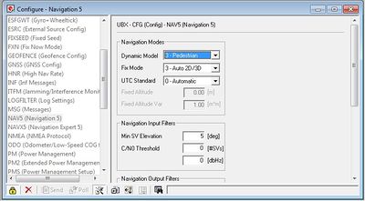
3-Activating the pedestrian mode
4-Refresh rate of the GPS to 10Hz
5-Using the GNSS constellation of choice. We used all the constellations so as to get a deferentially corrected position,there by increasing the accuracy
For detailed configuration settings refer the U-center guide [3]
Implementation
Algorithm
Testing
Performance Analysis of Compass
1. Compare the performance with the off-shelf compass module.
Make the heading angle given by compass module by rotating the compass, turn off the compass module, Place an off-shelf compass module exactly at the same place (direction same as pointed by Y axis of Magnetometer) note down the reading, rotate the compass by 90 degrees and repeat the same procedure. If the difference in all the readings is in within single digit, the performance of the compass is satisfactory.
2. Analyzing the 3D model of IMU on AHRS test using open GL processing framework.
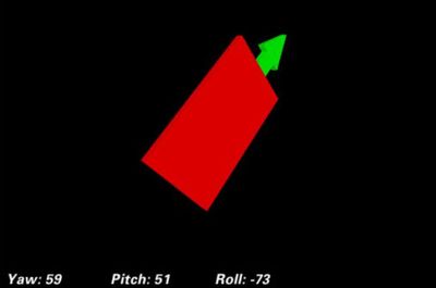
Periodically send yaw,pitch,roll values to the AHRS test application, to plot the 3D model of IMU. The plotted 3D model should mimic the rotation and movements of the IMU.
Technical Challenges
Soft Iron Effect for Compass
While Hard Iron Effects are constant and could be compensated by calibrating the offset, the soft iron effects are caused by the distortions produced by orientation of the material relative to the sensor and are not constant.
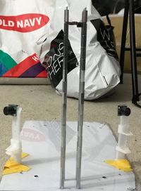
The initial mount for the compass module was made up of a string of stand-offs made up of aluminium.
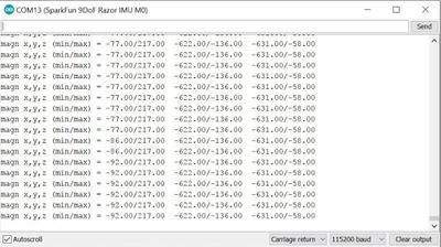
The magnetometer calibration tool based on processing framework plots the sample received from the IMU in a 2D plane, for a calibrated compass the value received from the magnet from the should lie inside the "Sphere of Magnet", however the values obtained were sprayed all over the place.
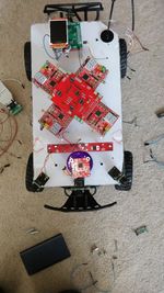
To resolve the issue, we modified our choice of material used, we used a stand made up of plastic to mount the compass on the car, and made a PCB to reduce the number of wires near the compass.
The values obtained after this changes were extremely stable, as shown in the figure in middle.
GPS offset drifting
The biggest problem was to determine whether our GPS module is working good, giving stable and accurate readings. Other than that the problems faced were:
1- The dynamic drifting of the GPS latitude and longitude values 2- Achieving the GPS lock 3- Isolating the exact NMEA message 4- Getting the highest precision of location 5- Configuring the baud rate to match the refresh rate of the GPS module to navigate the car accurately
Solutions to the problems:
The solution to the problem to determine whether our GPS module is working good, giving stable and accurate readings was to do analysis on the latitude ona longitude readings. For that we first need to understand the structure of the earth, the layout of latitude and longitude, and it's relation to distance between two points on earth.
The GPS lock is said to be achieved when there are 3 or more satellites tracking a GPS module. Initially when testing in the University rooms/buildings, it was difficult to get the GPS lock. The lock was achieved in the open area or in the regions where there was adequate space for the module to receive messages from the satellite. If the GPS lock is not present the GPS will not give you the proper readings of the location.
Image:
After having the GPS lock it was observed that there are multiple NMEA messages that are received from the module, making it difficult for us to exactly isolate the string of interest and extract the latitude and longitude values from it. NMEA messages are shown with heading $Gxyyy, where x stands for the satellite system (P = GPS, SBAS, QZSS, L = GLONASS, A = Galileo, B = BeiDou, N = Any combination of GNSS) and yyy for the type of message (e.g. ZDA=Time & Date). We then disabled the other NMEA messages from the system and only activated the GPGGA string, as that was what we were interested in. There are many NMEA formats available, the reason why we selected this was because this string provides the information about the number of satellites it has locked, as well as it gives high precision latitude and longitude values by using other GNSS constellation if enabled, discussed later below.
$GPGGA,HHMMSS.SS,DDMM.MMMMM,K,DDDMM.MMMMM,L,N,QQ,PP.P,AAAA.AA,M,±XX.XX,M,SSS,RRRR*CC<CR><LF>
where
image:
example:
$GPGGA,123519,4807.038,N,01131.000,E,1,08,0.9,545.4,M,46.9,M,,*47
Where:
    GGA          Global Positioning System Fix Data
    123519       Fix taken at 12:35:19 UTC
    4807.038,N   Latitude 48 deg 07.038' N
    01131.000,E  Longitude 11 deg 31.000' E
    1            Fix quality: 0 = invalid
                              1 = GPS fix (SPS)
                              2 = DGPS fix
                              3 = PPS fix
4 = Real Time Kinematic 5 = Float RTK
6 = estimated (dead reckoning) (2.3 feature)
7 = Manual input mode 8 = Simulation mode
    08           Number of satellites being tracked
    0.9          Horizontal dilution of position
    545.4,M      Altitude, Meters, above mean sea level
    46.9,M       Height of geoid (mean sea level) above WGS84
                     ellipsoid
    (empty field) time in seconds since last DGPS update
    (empty field) DGPS station ID number
    *47          the checksum data, always begins with *
To get the highest and accurate data from the GPS module we enabled the GNGGA string. The GNGGA is the deferentially corrected position from the multiple satellites, here N means we enabled the multiple satellite tracking for our module to obtain the precise location from the satellite.
Testing & Technical Challenges
Describe the challenges of your project. What advise would you give yourself or someone else if your project can be started from scratch again? Make a smooth transition to testing section and described what it took to test your project.
Include sub-sections that list out a problem and solution, such as:
<Bug/issue name>
Discuss the issue and resolution.
Conclusion
Conclude your project here. You can recap your testing and problems. You should address the "so what" part here to indicate what you ultimately learnt from this project. How has this project increased your knowledge?
Project Video
Upload a video of your project and post the link here.
Project Source Code
References
Acknowledgement
Any acknowledgement that you may wish to provide can be included here.
References Used
List any references used in project.
Appendix
You can list the references you used.
