Difference between revisions of "S17: Smart Health Gear"
Proj user5 (talk | contribs) (→Body Temperature Calculation) |
Proj user5 (talk | contribs) (→Testing & Technical Challenges) |
||
| Line 722: | Line 722: | ||
* We used the free version of Eagle Studio to design the PCB and this posed us with various limitations. | * We used the free version of Eagle Studio to design the PCB and this posed us with various limitations. | ||
* We tried to implement Blood pressure circuit within the PCB which included of three circuits including Signal Conditioning, Pump circuit, and Valve circuit. The free version did not provide the required dimensions of the PCB needed for this implementation. | * We tried to implement Blood pressure circuit within the PCB which included of three circuits including Signal Conditioning, Pump circuit, and Valve circuit. The free version did not provide the required dimensions of the PCB needed for this implementation. | ||
| − | * As a beginner it was difficult to find the libraries for the exact parts we needed. After searching online for all the exact description of the components, we could successfully search for the libraries of the corresponding parts. | + | * As a beginner, it was difficult to find the libraries for the exact parts we needed. After searching online for all the exact description of the components, we could successfully search for the libraries of the corresponding parts. |
* Mirroring effect during PCB production was a factor that we undermined initially, but while reviewing the PCB before giving for production we noticed the alignment and corresponding connections of various modules with the PCB and changed the header pins accordingly. | * Mirroring effect during PCB production was a factor that we undermined initially, but while reviewing the PCB before giving for production we noticed the alignment and corresponding connections of various modules with the PCB and changed the header pins accordingly. | ||
* Soldering of the components needed to be done carefully so as not to damage any of the components or PCB. | * Soldering of the components needed to be done carefully so as not to damage any of the components or PCB. | ||
| + | |||
| + | === Heart Rate Sensor === | ||
| + | * After analyzing I2C clock on a Digital Oscilloscope, we realized that the frequency set by Preet was actually double the required frequency. So we divided the final frequency by 2 to get the required frequency. | ||
=== Task synchronization issue === | === Task synchronization issue === | ||
Revision as of 00:57, 26 May 2017
Contents
- 1 Grading Criteria
- 2 Project Title
- 3 Abstract
- 4 Objectives & Introduction
- 5 Project Schedule
- 6 Parts List & Cost
- 7 Design & Implementation
- 7.1 Hardware Design
- 7.2 Software Design
- 7.3 Implementation
- 8 Testing & Technical Challenges
- 9 Conclusion
- 10 References
Grading Criteria
- How well is Software & Hardware Design described?
- How well can this report be used to reproduce this project?
- Code Quality
- Overall Report Quality:
- Software Block Diagrams
- Hardware Block Diagrams
- Schematic Quality
- Quality of technical challenges and solutions adopted.
Project Title
Smart Health Gear
Abstract
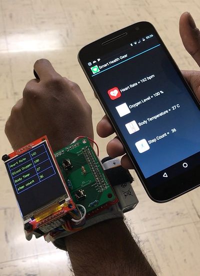
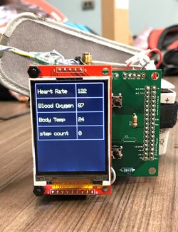
In today's fast paced Environment, more and more people are taking benefits of the latest technologies to keep track of their own fitness level and health. This helps them to make wise health decisions or take immediate action to improve their health by continuously monitoring vital health stats. Smart Health Gear is one such wearable device which will help in monitoring various aspects of a person's health like heart rate, blood oxygen level, footsteps count and body temperature. The device comes with a display unit that provides the user with current time as well as the aforementioned health stats on the go. It also comes with a compatible Bluetooth based Android application which will record the same details and makes it to available to the user. These can be recorded on a day-to-day basis which will enable in tracking these details over a period of time.
Objectives & Introduction
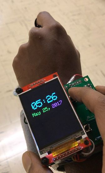
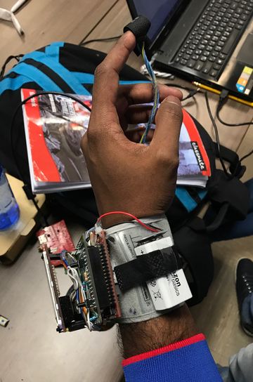
A wearable device that uses heart rate and pulse oximeter sensor to continuously monitor the heart rate and oxygen level in blood. The heart rate and oximeter sensor is connected on the I2C interface. It is also connected to a body temperature sensor wrap around the band to determine the body temperature. It serves as a watch as well by displaying the current time to the user which is fetched from the RTC on SJone board. The user can toggle between the clock and health stats using a switch and another switch to lock and unlock the screen as needed. It also comes with a notification screen that appears when something abnormal is detected in any of the health stats. A bluetooth module is interfaced with the device so that it can be paired with user's smartphone. An android application has also been developed so that the user can view these details via the app when connected via bluetooth.
The objectives are as follows:
- To be able to calculate and continuously monitor the heart rate
- To be able to calculate the oxygen level in blood
- To be able to calculate the body temperature
- To be able to calculate the step count of the person
- To be able to view all the vital details on a wearable device having LCD
- To be able to view the same details on an Android app
Team Members & Responsibilities
Project Schedule
| Sr. No. | Start Date | End Date | Task | Status | Actual Completion Date |
|---|---|---|---|---|---|
| 1 | 03/2/2017 | 03/2/2017 |
|
Completed | 03/2/2017 |
| 2 | 03/15/2017 | 03/30/2017 |
|
Completed | 03/30/2017 |
| 3 | 04/05/2017 | 04/16/2017 |
|
Completed | 04/20/2017 |
| 4 | 04/10/2017 | 04/16/2017 |
|
Completed | 04/25/2017 |
| 5 | 04/25/2017 | 04/30/2017 |
|
Completed | 05/06/2017 |
| 6 | 04/28/2017 | 05/04/2017 |
|
Completed | 05/08/2017 |
| 7 | 05/05/2017 | 05/10/2017 |
|
Completed | 05/12/2017 |
| 8 | 05/13/2017 | 05/16/2017 |
|
Completed | 05/20/2017 |
| 9 | 05/17/2017 | 05/21/2017 |
|
Completed | 05/25/2017 |
| 10 | 05/23/2017 | 05/23/2017 |
|
Completed | 05/25/2017 |
Parts List & Cost
| Item# | Part | Manufacturer | Part number | Cost($) |
|---|---|---|---|---|
| 1 | SJ One Board | Preet | N/A | 80.00 |
| 2 | Heart-Rate Monitor and Pulse Oximeter Sensor | Maxim | MAXREFDES117 | 20.00 |
| 3 | HC-06 wireless bluetooth transceiver | Banggood | Datasheet | 6.55 |
| 4 | 10K Precision Epoxy Thermistor - 3950 NTC | Adafruit | Lookup Table | 4.00 |
| 5 | LCD module | Aliexpress | SEN-10988 | 32.30 |
| 6 | Hardware | Excess Solution | Berg strips, Jumper wires, Connectors, Standoffs | 5.00 |
| 7 | 9V Battery | Amazon | 9.50 |
- Total Cost: 157.35$
Design & Implementation
Hardware Design
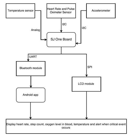
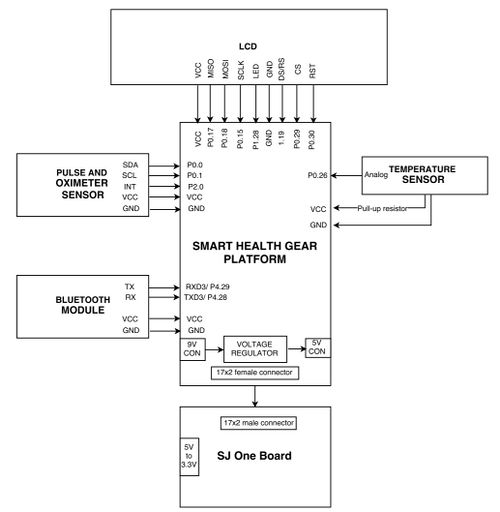
The below figure shows system design of our project including the interfaces for each sensor.
Heart Rate Sensor and Oximeter Sensor
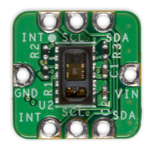
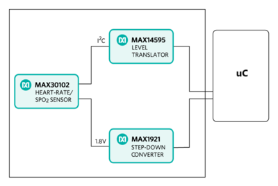
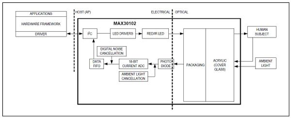
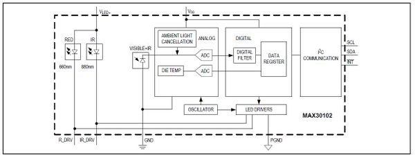
The Heart-Rate Monitor and Pulse Oximeter Sensor (MAXREFDES117) design is a Photoplethysmogram (PPG) based heart rate and SpO2 monitor subsystem. The module contains heart-rate/SpO2 sensor (MAX30102), a low-power step-down converter (MAX1921), and a level translator (MAX14595). The circuit utilizes the MAX30102 heart-rate/SpO2 sensor with integrated red and IR LEDs to detect heart rate and pulse ox on a person’s fingertip, earlobe. It should be powered on using a 2V to 5.5V supply. The step-down converter MAX1921 converts the 2V to 5.5V supply input and generates the 1.8V rail for the heart-rate sensor. The MAX14595 level translator provides an interface between the heart-rate/SpO2 sensor and the controller board, which generally use a different logic level.
It can be interfaced with using I2C communication and is fully adjustable through software registers, and the digital output data can be stored in a 32-deep FIFO within the IC. The SDA(P0.0) and SCL(P0.1) are connected on the I2C1 of the SJ-one board and interrupt is connected to GPIO pin on port 2 (P2.0) as shown on interface diagram. An interrupt is generated whenever it the FIFO gets filled and the samples are read as it gets filled.
Due to the form factor of the IC, it is ideal for wearable and it is can be clipped onto the finger of the person.
Temperature Sensor
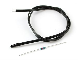
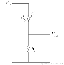
An NTC thermistor is used to compute the body temperature connected to the analog pin of the SJ-one board. A voltage divider circuit is connected to the analog pin of the board. A 10K resistor and thermistor are used in voltage divider circuit whose Vout is connected to analog pin as shown in the figure. Now you just measure the voltage in the middle, as the resistance changes, the voltage changes too, according to the simple voltage divider equation.
Features
- Resistance at 25 degrees C: 10K +- 1%
- B25/50 = 3950+- 1%
- Thermal time constant <= 15 seconds
- Thermistor temperature range -55 °C to 125 °C
- 28 AWG PVC Wire
LCD
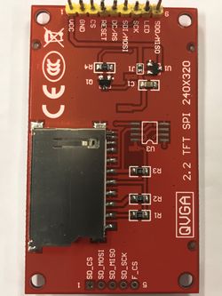
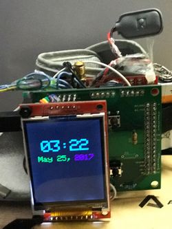
A LCD Display Screen is used to display the health stats collected from all the sensors of the user. It is interfaced to SJOne board via SPI. 2 GPIO pins are configured as Switches. Two Switches are used - One to switch on and off the LCD Interface, one more switch is used to Swap the screens from Timer Screen to Sensor Screen
Features:
- Display resolution: [240xRGB](H) x 320(V)
- a-TFT LCD driver with on-chip full display RAM: 172,800 bytes
- System Interface
- 3-line / 4-line serial interface [SPI/I2C]
- Display mode
- Full color mode (Idle mode OFF): 262K-color
- Reduce color mode (Idle mode ON): 8-color
- On chip functions
- Timing generator
- Oscillator
- DC/DC converter
- Line/frame inversion
- 4 preset Gamma curves with separate RGB Gamma correction
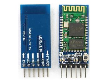
HC-05 Bluetooth Module
The HC-05 module is easy to use Bluetooth SPP (Serial Port Protocol) module, designed for transparent wireless serial connection setup. Serial port Bluetooth module is fully qualified Bluetooth V2.0+EDR (Enhanced Data Rate) 3Mbps Modulation with complete 2.4GHz radio transceiver and baseband. It uses CSR Bluecore 04-External single chip Bluetooth system with CMOS technology and with AFH(Adaptive Frequency Hopping Feature). It has the footprint as small as 12.7mmx27mm.
Hardware Features
- Typical -80dBm sensitivity
- Up to +4dBm RF transmit power
- Low Power 1.8V Operation, 1.8 to 3.6V I/O
- PIO control
- UART interface with programmable baud rate
- With integrated antenna
- With edge connector
Software Features
- Default Baud rate: 38400, Data bits:8, Stop bit:1, Parity: No parity, Data control: has.
Supported baud rate: 9600,19200,38400,57600,115200,230400,460800.
- Given a rising pulse in PIO0, the device will be disconnected.
- Status instruction port PIO1: low-disconnected, high-connected;
- PIO10 and PIO11 can be connected to red and blue led separately. When master and slave
are paired, red and blue led blinks 1time/2s in the interval, while disconnected only blue led blinks 2times/s.
- Auto-connect to the last device on power as default.
- Permit pairing device to connect as default.
- Auto-pairing PINCODE:"1234" as default
- Auto-reconnect in 30 min when disconnected as a result of beyond the range of connection.
Printed Circuit Board
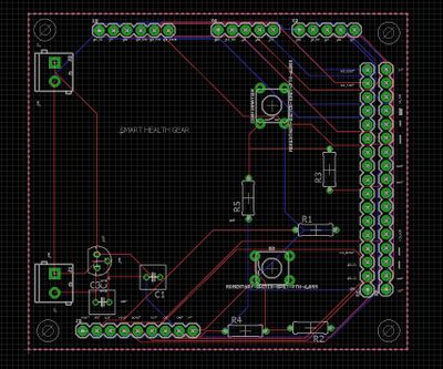
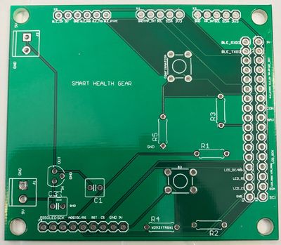
The PCB design was one of the challenging part of this project. The PCB design was created in Autodesk Eagle v8.1.0. Before proceeding with the schematic, we had decided to design a PCB that matches with the size of the SJ one board such that it could be mounted over it. Considering designing a wearable device, we had to keep in mind the form factor of the PCB. Initially we designed a PCB which turned out to be four-layer PCB including the blood pressure monitoring subsystem. However due to budget constraints we had to give up the blood pressure system as printing the same required a licensed version of Eagle.
Before starting the PCB schematic design, we decided on the location of sensors as it was vital for a wearable health monitoring device with a LCD display facing the user. Since surface mount soldering was not an option we decided to design the schematic with through hole connections. Another challenging part for our design was the libraries needed for schematic design. Since we didn’t have libraries for heart rate sensors, we had to design by creating it from scratch. However, we had some libraries from sparkfun, Eagle and Adafruit, the entire process took most of our time.
The first step in PCB design is to import all the libraries of the components that we would be using and create a schematic using the same. We made use of the Dimension tool in Eagle to match the PCB size with that of the SJ one board. We created the schematic by placing the required components and wiring them. The tutorial on Sparkfun website was very helpful in designing the same. It was very important for to ensure that all connections are verified properly before it gets printed. This was done using “DRC” Design Rule Check in Eagle which would show if any consistent errors existed.
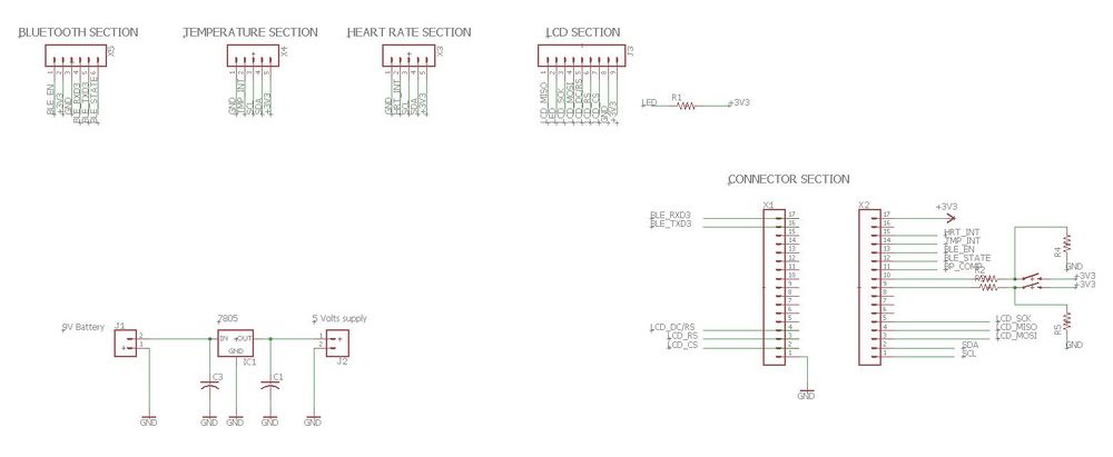
EAGLE Schematic
EAGLE Connector List
| Section | Connector | Library | Package | Device |
|---|---|---|---|---|
| Power Connector | 2x2-pin | SparkFun-Connectors | SCREWTERMINAL-3.5MM-2 | CONN_023.5MM (CONN_02) |
| SJ-One Board | 2x17-pin | SparkFun-Connectors | 1X17 | CONN_17 |
| Bluetooth Module | 1x6-pin | SparkFun-Connectors | 1X06 | CONN_06SILK_FEMALE_PTH (CONN_06) |
| Temperature Sensor | 1x5-pin | SparkFun-Connectors | 1X05 | CONN_05 |
| Heart Rate Sensor | 1x5-pin | SparkFun-Connectors | 1X05 | CONN_05 |
| LCD Section | 1x9-pin | SparkFun-Connectors | 1X09 | CONN_09 |
| Resistor | 5x2-pin | resistor | 0207/7 | R-US_0207/7 (R-US_) |
| Capacitor | 2x2-pin | rcl | C025-050X050 | C-US025-050X050 (C-US) |
| Switch | 2x4-pin | SparkFun-Switches | TACTILE_SWITCH_PTH_6.0MM | MOMENTARY-SWITCH-SPST-PTH-6.0MM (MOMENTARY-SWITCH-SPST) |
| LM7805 Regulator IC | 1x3-pin | v-reg | 78LXX | 78LXX |
Once the schematic is created that can be easily converted to Board Layout using the Generate/Switch to board option in Eagle. But this would create the board by randomly placing the parts at different locations. Since we had to have an LCD mount over the PCB as well as match the 17x2 connectors with that of SJ one board we created the design accordingly. After ensuring that everything was in place we placed order for the PCB and verified the same again using a multi-meter if all the connections were correct.
Hardware Interface Diagram
The below figure shows the interface diagram the connects the SJOne board with PCB and the various sensors and external power supply. As shown, all the SJOne pins were mapped to the PCB using a 17x2 connector and the PCB schematic was designed to match the project requirements of connecting sensors on relevant interfaces. The mapping and interfaces are shown clearly in the figure below. Also a voltage regulator was built that is used to provide 5V supply to SJone board from PCB using two phoenix connectors.
Software Design
Body Temperature Calculation
- Thermistor is connected to the analog pin across a voltage-divider circuit using a 10K resistor.
- Now you just measure the voltage in the middle, as the resistance changes, the voltage changes too, according to the simple voltage-divider equation.
- Based on the resistance value we can find the corresponding temperature value by matching it with the look-up table provided by the vendor.
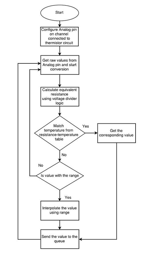
- The calculation of the temperature value is as shown in flowchart.
Pseudocode
- The thermistor is connected to the Analog pin on a channel to SJOne board
- The analog values are converted to discrete values using ADC peripheral in SJOne
- The values obtained can be used to calculate the voltage drop caused due to resistance
- Calculate the resistance based on the voltage drop
- Get the body temperature value from the look up table based on the resistance obtained
- If the resistance obtained does not match to any of the values in the look up table, the temperature value is calculated using interpolation
Software flowchart:
float temp = ((LS.getRawValue() *THREE_POINT_THREE)/4096);
      temp = THREE_POINT_THREE/temp;
      resistance = TEN/(temp - 1);
//Match resistance with look up table.
Heart rate Calculation
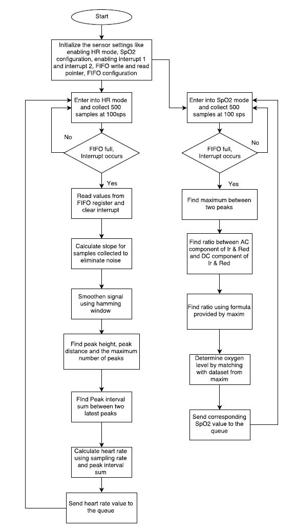
- The heart rate (bpm) is calculated by sensing the photoplethysmograph signal from the Pulse and Oximeter Sensor. By connecting the sensor on the I2C interface we get the raw values and collect about 100 samples every second.
- Initialize the sensor settings like enabling HR mode, SpO2 configuration, interrupt 1 and interrupt 2, FIFO write and read pointer, FIFO configuration by writing appropriate values into the registers as specified in the datasheet.
- The raw values contain noise as well so it is eliminated by finding derivative of the signal. For this purpose, we find the slope of the signal which would be series of either positive or negative number.
- To this derivative signal, a Hamming window is applied to smoothen out all edges and the signal is like a sine wave.
Software flowchart:
Algorithm Pseudocode:
- Read values from FIFO register whenever an interrupt occurs.
- Continuously take samples from MAX30102. The heart rate and SpO2 are calculated for every 1 second.
- Eliminate the first 100 samples from the register and calculate for every 500 samples by sliding the frame as samples occur.
- Find moving average of the sample raw values i.e slope calculation
- Apply Hamming window to the signal with window size as 5.
- Find peak height, peak distance and the maximum number of peaks.
- Find at most MAX_NUM peaks above MIN_HEIGHT separated by at least MIN_DISTANCE
- If the number of peaks < 2, find peak interval sum.
- Find the peak interval sum = time of the last peak – time of next peak.
- Based on the sampling rate, calculate the heart rate 6000/ peak interval sum and loop back to finding the peak.
- For SpO2 calculation, we need to assess DC and AC value of IR and red PPG.
- Find maximum between two peaks and use the ratio between AC component of Ir & Red and DC component of Ir & Red for SPO2.
- The accurate SPO2 is precalculated and save in uch_spo2_table[] per each ratio
- Ratio = -45.060*n_ratio_average* n_ratio_average/10000 + 30.354 *n_ratio_average/100 + 94.845
- Match the ratio as per the values in the table to get the correct SPO2 value.
if (n_npks>=2){
        for (k=1; k<n_npks; k++)
                n_peak_interval_sum += (an_dx_peak_locs[k]-an_dx_peak_locs[k -1]);
        n_peak_interval_sum=n_peak_interval_sum/(n_npks-1);
        *pn_heart_rate=(int32_t)(6000/n_peak_interval_sum);// beats per minutes
         *pch_hr_valid  = 1;
    }
Display Driver Design
Design
- Uses SPI interface to connect to the LCD
- The LCD interface is initialized by sending commands to set the power, frame rate, pixel depth etc.,
- The LCD screen is filled up pixel by pixel depending on what to display
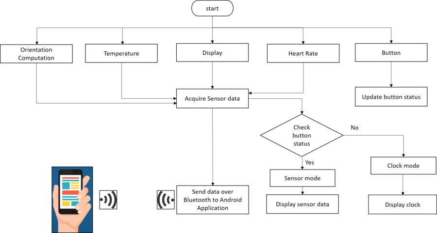
- Alternates between two screens - the Default Screen in which timer displays the current time and Sensor Screen which shows the data collected from all the sensors
- The data from each of the sensor tasks is sent to its dedicated queue and is received by the Display task
- Captures data continuously and displays on sensor screen
- There are two switches, one enables the user to turn on/off the LCD
- The user can also swap the screens by pressing the Sensor Screen button
- The timer will ensure that the sensor screen will swap back to the Timer screen after counting 300 times
Pseudocode
- Two Screens are available to be displayed on LCD i.e., Default screen with the current Time Stamp, Sensor Screen which displays the health stats of the user
- The Timer is initialized to count every 100 milli seconds and give screen change semaphore if the timer counts 300 times i.e., after 30 seconds.
- The timer gives timer_increment semaphore once the timer counts till 300
- There are two tasks running Display Task and The Button Task
- The display task waits for screen change semaphore. It checks watch_skins variable for the screen which needs to be displayed on the LCD.
- If the Timer screen needs to be displayed a function is called to check for any updates in time
- The timer is also used to check for the minute change, hour change, day change or year change. A function called minute check is used to notify the display task of any updates in time
- For any change in the time a dedicated semaphore is given which is captured by the display task.
- The address window that needs to be updated is cleared and the updated time received from RTC timer and is displayed
- If Sensor screen needs to be displayed the default screen with time stamp is cleared and Sensor screen is displayed
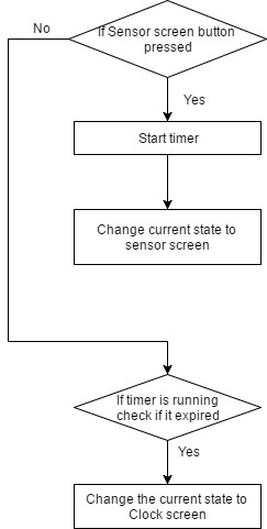
- The screen change semaphore is given when the timer expires or when the Screen change button is pressed.
- The button task monitors the button press for Sensor screen and the timer count.
- If the Sensor Screen button is pressed it sets the watch_screens variable to sensor screen and gives Screen change semaphore
- If it timer_increment semaphore is received it sets the watch_screens variable to clock screen and gives the screen change semaphore
Pseudocode to Display a String
- String is sent character by character to LCD.
- Each character is displayed by drawing pixel by pixel
- The address window is set first which positions the pixel in the right place
- The position of the pixel is determined by the character that should be printed and the number of characters displayed
- The commands Column Set and Row set along with command parameters will locate a pixel in the frame memory
- Memory Write command will then write the data in frame memory
- The loop continues till the character is displayed
- and so will run till the string is displayed
Software Flow Chart
Step count Calculation
- The step count is calculated using the values from the accelerometer on the SJ-on board. The accelerometer is connected on the I2C2 interface.
- Initialize the sensor settings, timer configuration, and I2C2 driver settings and load appropriate values into the registers as specified in the datasheet.
- The API is used to get the x-direction, y-direction and z-direction values from the accelerometer.
- It is calibrated using the initial values and step count is determined as given in the below pseudocode.
Software flowchart:
Algorithm Pseudocode:
1. Initialize the accelerometer on board sensor, timer, and I2C2 drivers.
2. Calibrate the accelerometer by collecting 25 sample readings along the X, Y and Z axis.
3. The collected samples are sorted in ascending order.
4. The reference value along all the axis are calculated by averaging the least and the highest value of the sorted array.
5. A 1-second timer is started and periodically 25 samples are collected, sorted and averaged to find the current acceleration along the three axes by a producer task.
6. Whenever a newly updated data is calculated, the preceding two values are stored to determine the peak condition. Hence, at any given time, consecutive three values (x_old, x_prev and x_th etc) are available for each axis, the current value being x_th)
7. Whenever the hand swings, the accelerometer readings significantly change and a peak condition is detected both during forward and backward swing.
8. As soon as a peak condition is detected the producer task increments the step count and passes it to the consumer task using a shared queue.
9. The consumer task then updates to the LCD display task and the Android App by pushing the updated count into the queue.
10. The system is re-calibrated at every 1 sec timeout for accurate results.
if(((x_old + 10 < x_prev )  && (x_th + 10 < x_prev )) )
{
	count = forw;
	step_Count++;
}
else if(((x_old > x_prev + 10)  && (x_th > x_prev + 10)))
{
	count = back;
	step_Count++;
}
Android Application
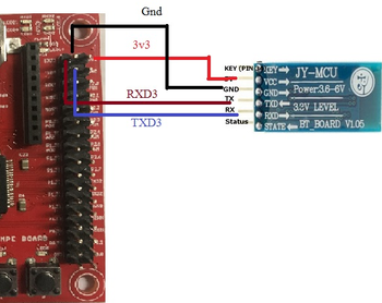
Development of the Android application is done using Android Studio Version 2.3.2. The application is connected to the HC-05 Bluetooth module using Bluetooth module. The HC-05, in turn, is interfaced with the SJOne board using Uart3 at the baud rate of 9600 bps. The connections are shown below. The data is sent to the module using serial communication nearly after every second and the value is simultaneously updated on the mobile application.
Android Studio is Android's official IDE. It offers tools custom-tailored for Android developers, including rich code editing, debugging, testing, and profiling tools. The Android app is built using 4 basic files namely AndroidManifest.xml, DeviceListActivity.java, MainActivity.java and activity_main.xml. Every application must have an AndroidManifest.xml file (with precisely that name) in its root directory. The manifest file provides essential information about your app to the Android system, which the system must have before it can run any of the app's code.
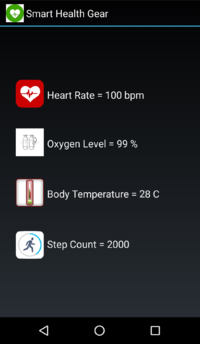
The layout of the Application has four text boxes to display the four different parameters of data i.e. Heart Rate, Body Oxygen Level, Body Temperature and Step Count.
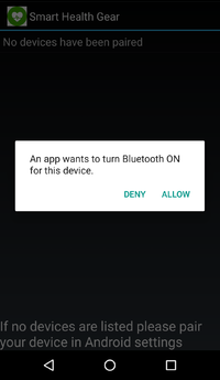
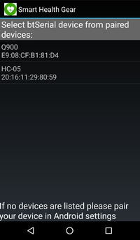
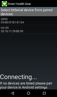
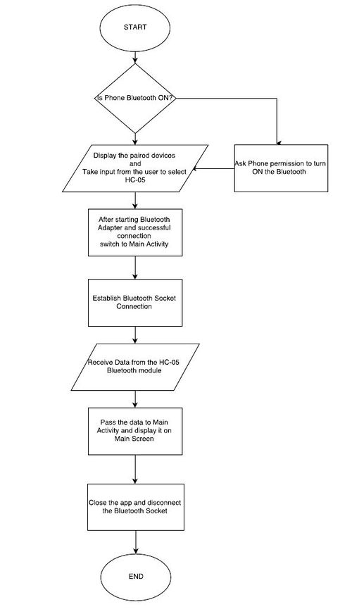
Upon opening the Application, if the Bluetooth connection of the Phone is not ON, the app will request permission to turn on Bluetooth. The first page of the application will display all the paired devices with the Phone. After selecting HC-05 among the list of paired devices, the app will connect to the module HC-05 and is ready to receive data from the module.
All the four parameters are passed in the format shown below:
Uart3& uart_3 = Uart3::getInstance();
uart_3.init(9600);
uart_3.printf("#%3d+%3d+%3d+%4d+~",heartRate, bodyOxygen, bodyTemp, stepCount);
On the application side, the above-received string is parsed accordingly to extract the value of each parameter and display it in the appropriate text box.
if (recDataString.charAt(0) == '#')		              //if it starts with # we know it is what we are looking for
{
  String sensor0 = recDataString.substring(1, 4);             //get sensor value from string between indices 1-5
  String sensor1 = recDataString.substring(5, 8);             //same again...
  String sensor2 = recDataString.substring(9, 12);
  String sensor3 = recDataString.substring(13, 17);

  sensorView0.setText(" Heart Rate = " + sensor0 + " bpm");	//update the textviews with sensor values
  sensorView1.setText(" Oxygen Level = " + sensor1 + " %");
  sensorView2.setText(" Body Temperature = " + sensor2 + " C");
  sensorView3.setText(" Step Count = " + sensor3 + "");
}Software flowchart:
Implementation
The software flow was designed such a way that interactive tasks such as display screen and Bluetooth module had to have high priority as it should be available to the user on demand. The sensor tasks each had a separate queue of depth 1 were the calculated values were sent. So, it gets dequeued in the display task and is updated whenever the screen is unlocked.
Below figure shows the complete implementation and task synchronization of the device.
Testing & Technical Challenges
PCB Designing
- We used the free version of Eagle Studio to design the PCB and this posed us with various limitations.
- We tried to implement Blood pressure circuit within the PCB which included of three circuits including Signal Conditioning, Pump circuit, and Valve circuit. The free version did not provide the required dimensions of the PCB needed for this implementation.
- As a beginner, it was difficult to find the libraries for the exact parts we needed. After searching online for all the exact description of the components, we could successfully search for the libraries of the corresponding parts.
- Mirroring effect during PCB production was a factor that we undermined initially, but while reviewing the PCB before giving for production we noticed the alignment and corresponding connections of various modules with the PCB and changed the header pins accordingly.
- Soldering of the components needed to be done carefully so as not to damage any of the components or PCB.
Heart Rate Sensor
- After analyzing I2C clock on a Digital Oscilloscope, we realized that the frequency set by Preet was actually double the required frequency. So we divided the final frequency by 2 to get the required frequency.
Task synchronization issue
- Being a user interactive product, it was important that the LCD and Android app is available to the user on demand. So we had to give high priority for the interactive tasks such as LCD display task and Bluetooth task.
- As a result of this, the sensor tasks went into starvation which was at a lower priority.
- To mitigate this, we made the high priority tasks sleep whenever no event occurred. Also, we used semaphores and mutex locks for cooperative scheduling between the sensor tasks.
LCD refresh issue
- The LCD screen refresh by filling the address window with the background color is very slow.
- We are instead filling the existing pixels with the background color.
- This is reducing the time taken by the Display to refresh and so the user can check the data quickly
Conclusion
This project has been successfully developed with almost all the decided features. The sensors work concurrently to communicate data to the Controller board. This real-time data is displayed on the LCD and also on the Android Application. We got to learn and implement various FreeRTOS features in this project to make this Project more robust while gaining knowledge about both the Hardware and Software fields. It was fun developing this project while integrating different sensors and output modules with the SJOne Board. We faced some issues at the start of the development phase but overcame those by taking appropriate decisions about the right sensors for Smart Health Gear project. We were also introduced to the world of PCB Designing which was exciting to learn and has given us a head start in a new doamin.
Project Video
Project Source Code
References
Acknowledgement
Any acknowledgement that you may wish to provide can be included here.
References Used
[1] FreeRTOS documentations
[2] Adafruit thermistor
[3] Adafruit LCD library
[4] FreeRTOS API
[5] MAXREFDES117 datasheet
[6] CMPE 244 Lecture notes from Preetpal Kang, Computer Engineering, San Jose State University. Jan-May 2017.
Appendix
You can list the references you used.
