Difference between revisions of "F16: Kasper"
Proj user16 (talk | contribs) (→Bluetooth Software Design) |
Proj user16 (talk | contribs) (→Team Members & Responsibilities) |
||
| Line 771: | Line 771: | ||
== Motor & I/O Controller == | == Motor & I/O Controller == | ||
=== Team Members & Responsibilities === | === Team Members & Responsibilities === | ||
| − | *''''' Chethan Keshava''''' | + | *'''''[https://www.linkedin.com/in/chethankeshava Chethan Keshava]''''' |
*'''''[https://www.linkedin.com/in/prashant-aithal-701086a7 Prashant Aithal] ''''' | *'''''[https://www.linkedin.com/in/prashant-aithal-701086a7 Prashant Aithal] ''''' | ||
Revision as of 23:07, 25 May 2017
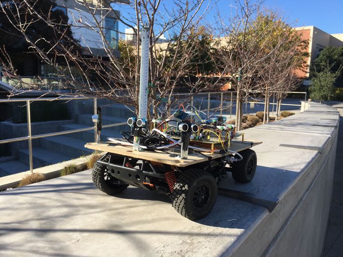
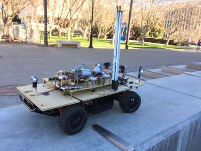
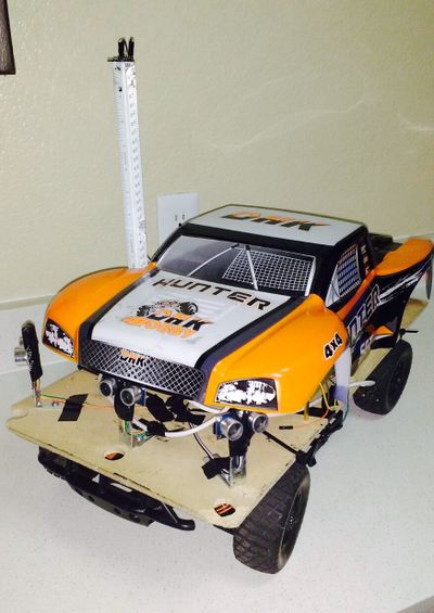
The project aims at developing a self driving car using the CAN protocol.
This report discusses in detail the various tasks involved in the development of the car and challenges faced.
Contents
- 1 Abstract
- 2 Objectives & Introduction
- 3 Team Members & Responsibilities
- 4 Team Schedule
- 5 Parts List & Cost
- 6 CAN Communication
- 7 Sensor Controller
- 8 Motor & I/O Controller
- 9 Geographical Controller
- 10 Communication Bridge Controller
- 11 Master Controller
- 12 Conclusion
- 13 References
Abstract
We are in an era of smart machines. With the self driving cars taking
over the roads these days, it is an interesting challenge to build our
own version of it.
This project aims at the implementation of such a self-driving car.
This self-driving RC car is based on CAN communication protocol which has been proven to be robust and deterministic
by the automotive industry. The controller used is the SJ-One Board.
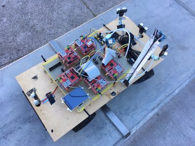
The overall driving of the car is divided across five modules:
Sensor: The sensor module essentially checks for obstacles in the driving path.
MotorIO: MotorIO drives the car using the underlying DC motor and Servo. LCD displays important information such sensor readings and GPS coordinates.
Geo: Geo controller is responsible for obtaining the location details and aid navigation.
Bridge: Bridge controller interfaces with the Android application where the path to be traversed is selected.
Master: Master co-ordinates the data from each of the modules and drives the MotorIO.
With all these implementations in place, the car will be able to drive itself to the destination.
Objectives & Introduction
The objective of this project is to build a self-driving car based on CAN protocol.
The self-driving car is intended to accomplish the following:
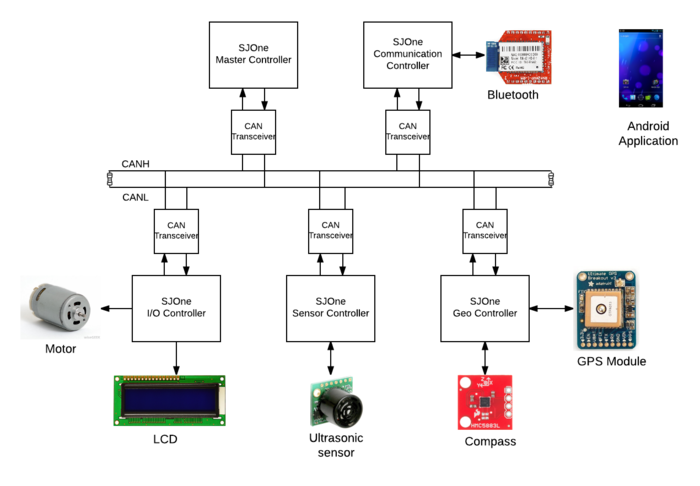
- The car is controlled via the Bluetooth application which is responsible for providing commands related to Start, Stop and Navigation Path of the car.
- The destination to be reached and the route to take in order to reach the destination are selected on the map using the Application.
- The checkpoints selected on the map are sent to the Bluetooth controller which is in turn sent to the Master Controller.
- The Master Controller is responsible for updating Geo Controller with the checkpoints as and when the car navigates.
- The Geo Controller provides the direction data which is useful for navigating from the current location to the nearest checkpoint.
- The Sensor Controller is responsible for detecting all the obstacles and providing the relevant obstacle data.
- Based on the Obstacle Avoidance data received from the sensors and the Navigation data received from the Geo Controller, the Master Controller needs provide commands to the Motor Controller to drive the motor towards the intended destination.
System Block Diagram
Team Members & Responsibilities
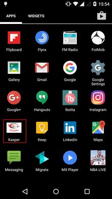
- Communication Bridge Controller (Application logo):
We have used five controllers
- Sensor Controller
- Shruthi Narayan
- Rimjhim Ghosh
- Color coding: Text
- Motor & I/O Controller
- Prashant Aithal
- Chethan Keshava
- Color coding: Text
- Geographical Controller
- Ankit Gandhi
- Color coding: Text
- Master Controller
- Aajna Karki
- Spoorthi Mysore Shivakumar
- Color coding: Text
- Communication Bridge Controller
- Bharat Khanna
- Shantanu Vasishtha
- Color coding: Text
Team Schedule
| Sl No. | Start Date | End Date | Task | Status | Actual Completion Date |
|---|---|---|---|---|---|
| 1 | 09/20/2016 | 09/27/2016 |
|
Completed | 09/27/2016 |
| 2 | 09/28/2016 | 10/04/2016 |
|
Complete | 10/04/2016 |
| 3 | 10/05/2016 | 10/11/2016 |
|
Completed | 10/11/2016 |
| 4 | 10/12/2016 | 10/18/2016 |
|
Completed | 10/18/2016 |
| 5 | 10/19/2016 | 11/01/2016 |
|
Completed | 11/01/2016 |
| 6 | 11/01/2016 |
CAN COMMUNICATION DEMO |
Completed | 11/01/2016 | |
| 7 | 11/01/2016 | 11/07/2016 |
|
Completed | 11/01/2016 |
| 8 | 11/08/2016 |
PROJECT PROTOTYPE DEMO |
Completed | 11/07/2016 | |
| 9 | 11/08/2016 | 11/15/2016 |
|
Completed | 11/08/2016 |
| 10 | 11/16/2016 | 11/29/2016 |
|
Completed | 11/15/2016 |
| 11 | 11/29/2016 |
PROJECT PROTOTYPE DEMO 2 |
Completed | 11/29/2016 | |
| 12 | 11/29/2016 | 12/06/2016 |
|
Completed | 12/06/2016 |
| 13 | 12/07/2016 | 12/15/2016 |
|
Completed | 12/15/2016 |
| 14 | 12/21/2016 |
FINAL PROJECT DEMO |
Completed | 12/21/2016 | |
| 15 | 12/20/2016 |
PROJECT REPORT SUBMISSION |
Completed | 12/20/2016 | |
Parts List & Cost
| Item# | Part Desciption | Vendor | Qty | Cost $ |
|---|---|---|---|---|
| 1 | RC Car | From Preet | 1 | 0 |
| 2 | SJOne board | Preet | 5 | 80 |
| 3 | GPS Module | Adafruit | 1 | 40 |
| 4 | Triple Axis Magnetometer (Compass) | Sparkfun | 1 | 15 |
| 5 | Bluetooth Module | Sparkfun | 1 | 24.95 |
| 6 | LCD screen | Adafruit | 1 | 24.95 |
| 7 | Ultrasonic sensor | Sparkfun | 1 | 27.95 |
| 8 | Jumper cable | Amazon | 1 | 9.99 |
| 9 | DB9 Connector | HSC | 1 | 1 |
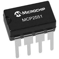
| 10 | CAN Transceiver | Microchip | 10 | 10 |
CAN Communication
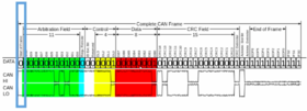
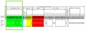
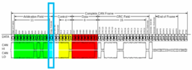
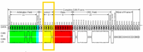
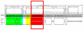
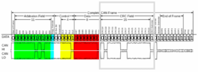
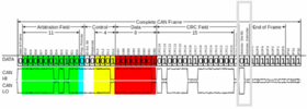
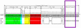
CAN (Controller Area Network) also known as CAN bus is a vehicle bus that is designed to communicate with microcontrollers and other devices to achieve a specific application. It finds great application in the automotive industry. Shown below is CAN frame along with logical and electrical values.
| Figure No.. | Field Name | Length (bits) | Description |
|---|---|---|---|
| 1 | CAN frame | - | CAN frame with 11 identifier bits. |
| 2 | Start-of-frame | 1 | Denotes the start of frame transmission and indicates beginning of message. It starts with dominant logic 0 bit. |
| 3 | Arbitration Field | 11 | This identifies the messages and indicates the message priority. |
| 4 | Remote Transmission Request (RTR) | 1 | Differentiates remote frame from a data frame. Must be dominant (0) for data frames and recessive (1) for remote request frames. |
| 5 | Data Length Code (DLC) | 4 | Number of bytes of data. This field indicates how much data is stored inside. |
| 6 | Data Field | 0-64 (0-8 Bytes) | Data to be transmitted. |
| 7 | CRC | 16 | This is a 16-bit cyclic redundancy check code along with CRC delimiter. |
| 8 | Acknowledgement | 2 | Acknowledge bits. |
| 9 | End-of-frame (EOF) | 7 | End of frame bits. Msut be all recessive. |
DBC File Implementation
The DBC file used for the project is as below:
VERSION ""
NS_ :
 BA_
 BA_DEF_
 BA_DEF_DEF_
 BA_DEF_DEF_REL_
 BA_DEF_REL_
 BA_DEF_SGTYPE_
 BA_REL_
 BA_SGTYPE_
 BO_TX_BU_
 BU_BO_REL_
 BU_EV_REL_
 BU_SG_REL_
 CAT_
 CAT_DEF_
 CM_
 ENVVAR_DATA_
 EV_DATA_
 FILTER
 NS_DESC_
 SGTYPE_
 SGTYPE_VAL_
 SG_MUL_VAL_
 SIGTYPE_VALTYPE_
 SIG_GROUP_
 SIG_TYPE_REF_
 SIG_VALTYPE_
 VAL_
 VAL_TABLE_
BS_:
BU_: MASTER GEO SENSOR MOTORIO BRIDGE
BO_ 100 STOP_CAR: 1 MASTER
 SG_ STOP_CAR_data : 0|8@1+ (1,0) [0|0] "" BRIDGE,GEO,SENSOR,MOTORIO

BO_ 110 RESET: 1 MASTER
 SG_ RESET_data : 0|8@1+ (1,0) [0|0] "" BRIDGE,GEO,SENSOR,MOTORIO
BO_ 130 STOP_CMD_APP: 1 BRIDGE
 SG_ STOP_CMD_APP_data : 0|8@1+ (1,0) [0|0] "" MASTER

BO_ 140 START_CMD_APP: 1 BRIDGE
 SG_ START_CMD_APP_data : 0|8@1+ (1,0) [0|0] "" MASTER
BO_ 400 SENSOR_SONIC: 4 SENSOR
 SG_ SENSORS_SONIC_front_left : 0|16@1+ (1,0) [0|0] "" MASTER,MOTORIO
 SG_ SENSORS_SONIC_front_right : 16|16@1+ (1,0) [0|0] "" MASTER,MOTORIO
 SG_ SENSORS_SONIC_front_center : 32|16@1+ (1,0) [0|0] "" MASTER,MOTORIO
 SG_ SENSORS_SONIC_back : 48|16@1+ (1,0) [0|0] "" MASTER,MOTORIO

BO_ 410 MOTORIO_DIRECTION: 3 MASTER
 SG_ MOTORIO_DIRECTION_speed : 0|8@1+ (1,0) [0|10] "" MOTORIO
 SG_ MOTORIO_DIRECTION_turn : 8|8@1+ (1,-4) [-3|3] "" MOTORIO
 SG_ MOTORIO_DIRECTION_direction : 16|8@1+ (1,0) [0|2] "" MOTORIO
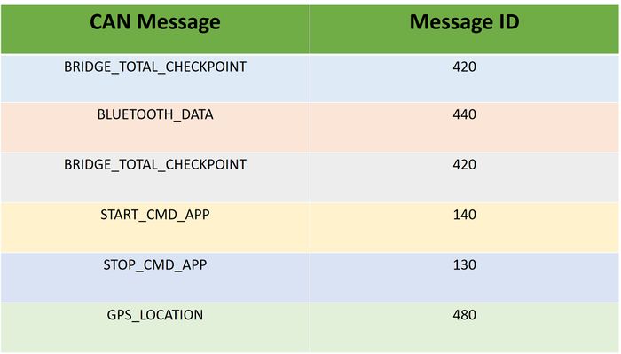
BO_ 420 BRIDGE_TOTAL_CHECKPOINT: 1 BRIDGE
 SG_ BRIDGE_TOTAL_CHECKPOINT_NUMBER : 0|8@1+ (1,0) [0|0] "" MASTER,MOTORIO

BO_ 430 RECEIVE_START_ACK: 1 MASTER
 SG_ RECEIVE_START_ACK_ack : 0|8@1+ (0,0) [0|0] "" BRIDGE

BO_ 440 BLUETOOTH_DATA: 8 BRIDGE
 SG_ BLUETOOTH_DATA_LAT : 0|32@1+ (0.000001,0) [0|0] "" MASTER
 SG_ BLUETOOTH_DATA_LON : 32|32@1+ (0.000001,-127) [0|0] "" MASTER
BO_ 450 NEXT_CHECKPOINT_DATA: 8 MASTER
 SG_ NEXT_CHECKPOINT_DATA_latitude : 0|32@1+ (0.000001,0) [0|0] "" GEO
 SG_ NEXT_CHECKPOINT_DATA_longitude : 32|32@1+ (0.000001,0) [0|0] "" GEO

BO_ 460 COMPASS_DATA: 5 GEO
 SG_ COMPASS_DATA_speed : 0|8@1+ (1,0) [0|0] "" MASTER
 SG_ COMPASS_DATA_heading : 8|16@1+ (1,0) [0|0] "" MASTER
 SG_ COMPASS_DATA_bearing : 24|16@1+ (1,0) [0|0] "" MASTER

BO_ 470 CURRENT_LOCATION_ACK: 1 BRIDGE
 SG_ CURRENT_LOCATION_ACK_ack : 0|8@1+ (1,0) [0|0] "" MASTER,GEO

BO_ 480 GPS_LOCATION: 8 GEO
 SG_ GPS_LOCATION_latitude : 0|32@1+ (0.000001,0) [0|0] "" MASTER,BRIDGE
 SG_ GPS_LOCATION_longitude : 32|32@1+ (0.000001,0) [0|-127] "" MASTER,BRIDGE

BO_ 490 DISTANCE_TO_DESTINATION: 1 GEO
 SG_ DISTANCE_TO_DESTINATION_data : 0|8@1+ (0,0) [0|0] "" MASTER, MOTORIO
BO_ 500 BATTERY_STATUS: 1 SENSOR
 SG_ DISTANCE_TO_DESTINATION_status : 0|8@1+ (0,0) [0|0] "" MASTER, MOTORIO
CM_ BU_ DRIVER "Master Controller";
CM_ BU_ SENSOR "Sensor Controller";
CM_ BU_ MOTORIO "Motor I/O controller";
CM_ BU_ BRIDGE "BRIDGE Controller";
CM_ BU_ GEO "Geo Controller";
CM_ BO_ 2 "Sync message used to synchronize the controllers";
BA_DEF_ "BusType" STRING ;
BA_DEF_ BO_ "GenMsgCycleTime" INT 0 0;
BA_DEF_ SG_ "FieldType" STRING;
BA_DEF_DEF_ "BusType" "CAN";
BA_DEF_DEF_ "FieldType" "";
BA_DEF_DEF_ "GenMsgCycleTime" 0;
BA_ "GenMsgCycleTime" BO_ 400 	          10;
BA_ "GenMsgCycleTime" BO_ 410             10;
BA_ "GenMsgCycleTime" BO_ 450             10;
BA_ "GenMsgCycleTime" BO_ 460             10;
BA_ "GenMsgCycleTime" BO_ 470             10;
BA_ "GenMsgCycleTime" BO_ 480             10;
PCAN Dongle and BUS Master
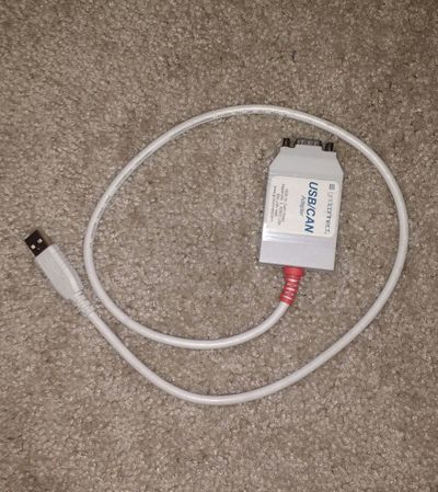
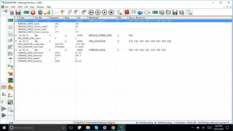
The DB9 connector is interfaced to the CAN bus. Using this interface, we can monitor the CAN bus through a tool called BusMaster. PCAN Dongle is used to view the CAN messages on the CAN Bus on the GUI. This has helped us in debugging CAN related errors on all the 5 controllers.
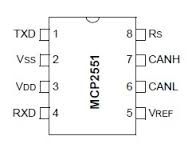
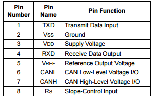
Can Transceiver
Sensor Controller
Team Members & Responsibilities
- Shruthi Narayan
- Rimjhim Ghosh
Schedule
| SI No. | Start Date | End Date | Task | Status | Actual Completion Date |
|---|---|---|---|---|---|
| 1 | 10/5/2016 | 10/11/2016 |
|
Completed | 10/9/2016 |
| 2 | 10/12/2016 | 10/18/2016 |
|
Completed | 10/18/2016 |
| 3 | 10/19/2016 | 10/25/2016 |
|
Completed | 10/25/2016 |
| 4 | 10/26/2016 | 11/1/2016 |
|
Completed | 11/1/2016 |
| 5 | 11/2/2016 | 11/8/2016 |
|
Completed | 11/8/2016 |
| 6 | 11/9/2016 | 11/15/2016 |
|
Completed | 11/15/2016 |
| 7 | 11/16/2016 | 11/22/2016 |
|
Completed | 11/22/2016 |
| 8 | 11/23/2016 | 11/29/2016 |
|
Completed | 11/29/2016 |
| 9 | 11/30/2016 | 12/6/2016 |
|
Completed | 12/5/2016 |
| 10 | 12/7/2016 | 12/17/2016 |
|
Completed | 12/16/2016 |
Hardware Design
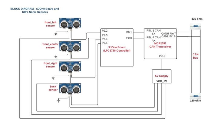
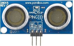
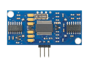
Four Parallax Ping ultrasonic distance sensors are used in this project for obstacle detection and avoidance.
Non-contact obstacle distance can be measured from about 2 cm (0.8 inches) to 3 meters (3.3 yards).
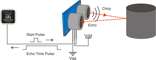
The PING))) sensor works by transmitting an ultrasonic burst and providing an output pulse that corresponds to the time required for the burst echo to return to the sensor. By measuring the echo pulse width, the distance to target can easily be calculated.
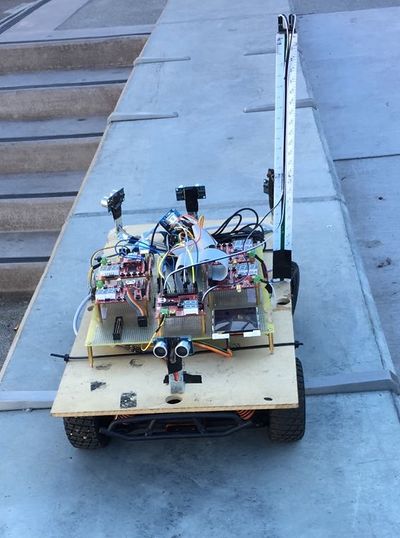
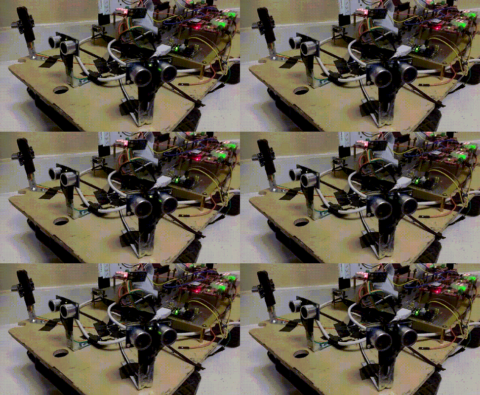
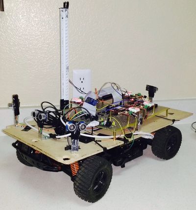
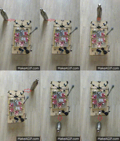
Four Sensors are mounted on the car.
Three in the front: front_left, front_center, front_right
One at the back: back
This data related to obstacle detection from each of the four sensors is communicated to the Master Controller over the CAN bus.
In the above picture, Burst indicator LED blinking shows measurement in progress.
The image below shows the wired connections between sensors and SJOne board.
Software Design
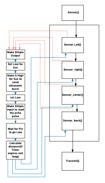
Operation Squence:
Software timer for triggering sensor:
All sensors are triggered using software timers. A soft timer is declared for each sensor which keeps track of the time between trigger and echo for that particular sensor.
#define Echo_Return_Pulse 18.5
SoftTimer ping_duration_left;
ping_duration_left.reset(Echo_Return_Pulse);
ping_duration_left.restart();
Hardware timer for calculating distance:
The declaration of hardware timer is as shown below:
lpc_timer_enable(lpc_timer0,1); /*enable timer0*/
lpc_timer_set_value(lpc_timer0,0); /*set timer0 value=0*/
Distance Calculation:
Distance=Speed * Time
The distance covered by the sound wave is twice the actual distance.
Therefore, Distance= (Speed * Time)/2
Speed of sound=340m/s, 1m=100cm, 1us=0.000001 s
Distance covered in 1us= (340*100*0.000001)/2 = 0.017cm
#define Distance_Scale 0.017
time_left = lpc_timer_get_value(lpc_timer0);
distance_left = (Distance_Scale)*time_left;
Ranging:
LeftSIG.setAsOutput(); /*make SIGpin output*/
LeftSIG.setLow(); /*set low for 2us and then high for clean high*/
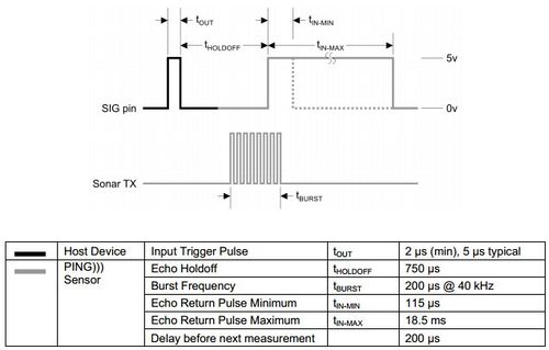
delay_us(2);
LeftSIG.setHigh(); /* enable Ranging (enable left sonar). trigger/set high for 2 µs (min), 5 µs typical. Ultrasonic burst*/
delay_us(5);
LeftSIG.setLow(); /*set low*/
LeftSIG.setAsInput(); /*make SIGpin input*/
Implementation
Sensor Testing: LV-MaxSonar-EZ(MB1010):
• This sensor gives a range of 0 inches to 254 inches with a voltage supply of 5V.
• Using multiple ultrasonic sensors in a single system caused interference (crosstalk) so the sensors were triggered sequentially which reduced the fluctuating values
• The range reading time of Maxbotix LV-MaxSonar-EZ1 is 49 ms for a range of 254 inches (6.54 m) requirement was to send all sensor values in 10 Hz. Only 2 sensor values could be sent.
• Having the requirement to send the sensor readings in 10Hz, we reduced the delay between the sensors to 15ms covering a range of 101 inches. Send values of all the four sensors (left, center, right, back) in 10Hz using chaining process.
• Even after this there were frequent abrupt values encountered in the readings so considering the fluctuations and requirement we switched to parallax ping sensors.
Sensor Testing: Parallax Ping
Pin Configuration
Pin1: GND- Ground pin
Pin2: 5V- Voltage Supply pin
Pin3: SIG- Signal Pin- This emits a short 40Khz burst acting as a trigger pin then the same pin starts listening the echo.
Ping Sensor Features
• Provides precise, non-contact distance measurements within a 2 cm to 3 m range
• Simple pulse in/pulse out communication requires just one I/O pin
• Burst indicator LED shows measurement in progress
• 3-pin header makes it easy to connect to a development board, directly or with an extension cable, no soldering required
• The PING))) sensor works by transmitting an ultrasonic (well above human hearing range) burst and providing an output pulse that corresponds to the time required for the burst echo to return to the sensor. By measuring the echo pulse width, the distance to target can easily be calculated.
The PING))) sensor detects objects by emitting a short ultrasonic burst and then "listening" for the echo. Under control of a host microcontroller (trigger pulse), the sensor emits a short 40 kHz (ultrasonic) burst. This burst travels through the air, hits an object and then bounces back to the sensor. The PING))) sensor provides an output pulse to the host that will terminate when the echo is detected, hence the width of this pulse corresponds to the distance to the target.
Ping Sensor Considerations for use:
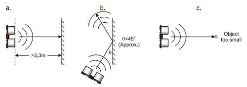
The PING))) sensor cannot accurately measure the distance to an object that:
- is more than 3 meters away
- that has its reflective surface at a shallow angle so that sound will not be reflected back towards the sensor
- is too small to reflect enough sound back to the sensor
- if the sensor is mounted low on the device, it will detect sound reflecting off of the floor.
Testing & Technical Challenges
Issue 1: Triggering of Sensors in Parallel
Triggering all the sensors in parallel causes interference between adjacent sensors, which in turn causes mis-firing of echo. This results in incorrect distance values from all the sensors.
Solution: Sequential triggering of Sensors Each sensor is triggered only when the previous sensor receives an echo or exceeds the maximum echo reception wait time which is 18.5ms.
Issue 2: Sensor Angle
The Left and Right sensors gave faulty values when placed at an acute angle on the corner of the base board.
Solution: angle>45
Increased the angle to cover wider area and avoid reflections. Increasing the angle to more than 45 degrees helped us get accurate values.
Motor & I/O Controller
Team Members & Responsibilities
Schedule
| SI No. | Start Date | End Date | Task | Status | Actual Completion Date |
|---|---|---|---|---|---|
| 1 | 09/27/2016 | 10/04/2016 |
|
Completed | 10/04/2016 |
| 2 | 10/04/2016 | 10/11/2016 |
|
Completed | 10/07/2016 |
| 3 | 10/11/2016 | 10/18/2016 |
|
Completed | 10/15/2016 |
| 4 | 10/18/2016 | 10/25/2016 |
|
Completed | 10/24/2016 |
| 5 | 10/25/2016 | 11/1/2016 |
|
Completed | 11/1/2016 |
| 6 | 11/1/2016 | 11/15/2016 |
|
Completed | 11/15/2016 |
| 7 | 11/15/2016 | 11/28/2016 |
|
Completed | 11/28/2016 |
| 8 | 11/28/2016 | 12/05/2016 |
|
Completed | 12/20/2016 |
Pulse Width Modulation
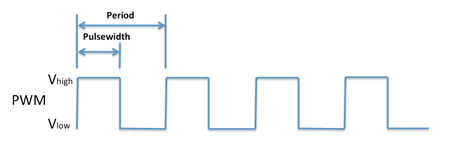
Pulse-width modulation (PWM), is a modulation technique which encodes a message into a pulsing signal. Pulse width modulation is a type of digital signal. It is mainly used to control the power supplied to electrical devices such as motors. Pulse width modulation is used in a variety of applications including sophisticated control circuitry. PWM pulse are supplied to the DC and Servo motors in our project. They help in rotating and turning the wheels of the RC car, respectively.
Duty Cycle
When the signal is high this is the “ON time”. To describe the amount of “on time” the concept of duty cycle is introduced. Duty cycle is measured in percentages. The percentage duty cycle specifically describes the percentage of time a digital signal is ON over an interval or period of time. This period is the inverse of the frequency of the waveform.
If a digital signal spends half of the time ON and the other half OFF, we would say the digital signal has a duty cycle of 50% and resembles an ideal square wave. If the percentage is higher than 50%, the digital signal spends more time in the high state than the low state and vice versa if the duty cycle is less than 50%.
Electronic Speed Controller
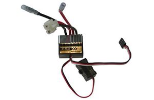
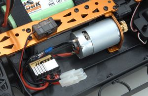
An electronic speed control or ESC is an electronic circuit which is used to vary the electric motor's speed.It also behaves as a dynamic brake. ESCs are used on electrically powered radio controlled cars, essentially providing an electronically generated three-phase electric power low voltage source of energy for the motor.
There are two different types of RC motors, brushed and brushless. Each motor type has its own kind of ESC (Electronic Speed Controller). Without an ESC, the DC motor of the RC car would either not move or it will go at full throttle when the car is driven. Brushed motors are cheap but very ineffecient and lack power. Brushless motors are efficient, powerful, fast, and last much longer. The main visual difference between the two is that the brushless is sealed completely and has three wires, while the brushed has ventilation holes and two wires.
Servo Motor
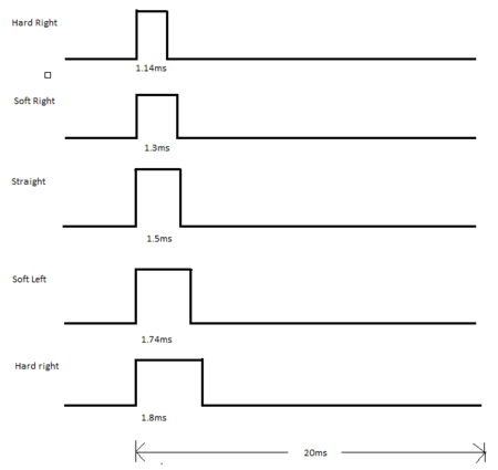
The RC car came with a digital servo motor. The motor works without ESC. The motor is controlled by giving PWM signal from the SJOne board. RC Servos are used to convert electrical signal into polar or linear movement. When signal is transmitted from the control to the car, this signal is decoded and sent to a servo. According to this signal, the servo will rotate it's drive shaft by some degrees, and this rotation is translated into wheel steering. The power supply of servos is usually from 3 to 5 volts.
The RC servos are controlled with a PWM signal driven to their signal wire. A PWM signal has three parameters that characterizes it: The first is the amplitude (or peak to peak voltage) of the signal which is around 3 to 5 volts according to it's specifications. The second is the frequency. In PWM, the frequency is usually fixed to a value.The third and most critical value is the positive pulse width of the PWM, i.e. the "duty cycle". The width of the pulse will have a direct result into the drive shaft position.
Servo Motor Connections
| ESC Wire Pins | SJOne Board Pins |
|---|---|
| Vcc | 3V3 |
| GND | GND |
| Turn Control | P2.0 |
Servo motor is controlled with the help of three wires coming out of the servo motor. The wires are VCC, GND and Direction control. The VCC is connected to the 3.3v. GND and direction control are connected to the ground and pwm pins of SJOne board.
DC Motor
A DC motor converts direct current electrical power into mechanical power. The most common types rely on the forces produced by magnetic fields.
Pulse width modulation (PWM) is used to control the motor. One advantage is that the power loss in the switching transistor is small because the transistor is either fully “ON” or fully “OFF”. The RC Car came with the motor that needed 7.4V of power supply to work. The motor has the power to run the car at a maximum speed of 35mph. DC motor is controlled with the help of three wires coming out of the ESC. These wires are VCC, GND and Speed control.
Place the car on a raised platform in such a way that the wheels of the car are not touching any surface. Given below is the code snippet for testing out the dc motors using the on-board switches of the SJ One circuit.
        if(SW.getSwitch(1))
	{
		dc_stop();
	}
	else if(SW.getSwitch(2))
	{
		dc_accelerate(6.4);
	}
	else if(SW.getSwitch(3))
	{
		dc_accelerate(6.2);
	}
	else if(SW.getSwitch(4))
	{
		dc_accelerate(7.6);
	}
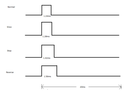
On pressing the on-board switches the wheels of the car would rotate at different speeds.Pressing switch 2 and 3 would make the wheels rotate in he forward direction. The value of the PWM duty cycle can be varied to try out different speeds. Pressing Switch 1 would stop the rotation of the wheel. Switch 4 allows the reversing of the rotation of the wheel. On pressing these switches, either of two functions, shown below are called.
void dc_accelerate(float pwmValue)
{
	MotorControl.setDC(pwmValue);
	stop_flag = true;
}

void dc_stop(void)
{
	if(stop_flag)
	{
		MotorControl.setDC(DC_STOP);
		stop_flag = false;
	}
}
MotorControl is an object from the MotorController singleton class. The Motorcontroller class has 2 functions-setDC() and setServo(). setDC() is used to drive the car while setServo() is used to control the turning of the car.
DC Motor Connections
| ESC Wire Pins | SJOne Board Pins |
|---|---|
| Vcc | - |
| GND | GND |
| Speed Control | P2.1 |
The VCC line is not used as the required voltage is directly given to the motor through a battery, via ESC. The GND line and Speed control lines are connected to the ground and PWM pin of SJOne board.The DC motor was driven using PWM2 i.e. pin P2.1 of the SJOne board. In-built PWM generation function was used. It requires two parameters, one is pin being used and the other being the frequency.
Motor/IO Controller Software Design
Tasks
| Task Name | Purpose |
|---|---|
| Period Init | CAN Bus Initialization, Reset CAN Bus |
| Periodic 1Hz Callback | Check if CAN bus off and Reset bus. Reset the RPM counter. Send data to LCD. |
| Periodic 10Hz Callback | Drive car according to the commands received from Master controller |
Motor Pin Connections
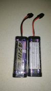
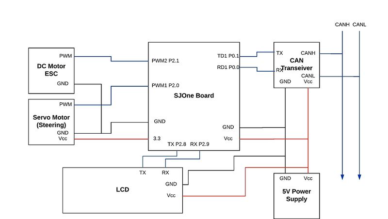
The car runs on Ni-MH batteries. The battery powers the ESC unit, which in turn drives the motor and also powers the steering servo. The SJ One board, ESC unit and steering servo should share a common ground in order for the PWM signals to have the same reference voltage. The CAN transceiver uses the 5V power supply and GND, along with the P0.0 (CAN RX) and P0.1 (CAN TX) of the SJ One Board. P2.0 (PWM1) and P2.1 (PWM2) controls the steering and motor respectively. This is done by sending out PWM signals from the SJ One board that change the width of a 20ms period waveform. 1ms width represents a 0% duty cycle, 1.5ms width represents a 50% duty cycle, and 2ms width represents a 100% duty cycle.
| Node A Source | Node A Pin | Node B Source | Node B Pin | Description |
|---|---|---|---|---|
| 3.3V Power Supply | 3.3V | SJOne Board | 3V3 | SJOne Power |
| 3.3V Power Supply | GND | SJOne Board | GND | SJOne Ground |
| CAN Transceiver | CAN Tx | SJOne Board | P0.1 (Tx) | SJOne - CAN Tx |
| CAN Transceiver | CAN Rx | SJOne Board | P0.0 (Rx) | SJOne - CAN Rx |
| CAN Transceiver | 5V | 5V Power Supply | 5V | SJOne - CAN Power |
| CAN Transceiver | Ground | 5V Power Supply | GND | SJOne - CAN Ground |
| CAN Transceiver | CANL | CAN BUS | CANL | CANL to CAN BUS |
| CAN Transceiver | CANR | CAN BUS | CANR | CANR to CAN BUS |
| Steering Servo | PWM Port | SJOne Board | P2.0 PWM | Steering Control |
| Steering Servo | Ground | SJOne Board | GND | Common ground for reference voltage |
| ESC/Motor | PWM Port | SJOne Board | P2.1 PWM | Motor Control |
| ESC/Motor | Ground | SJOne Board | GND | Common ground for reference voltage |
Hardware Design
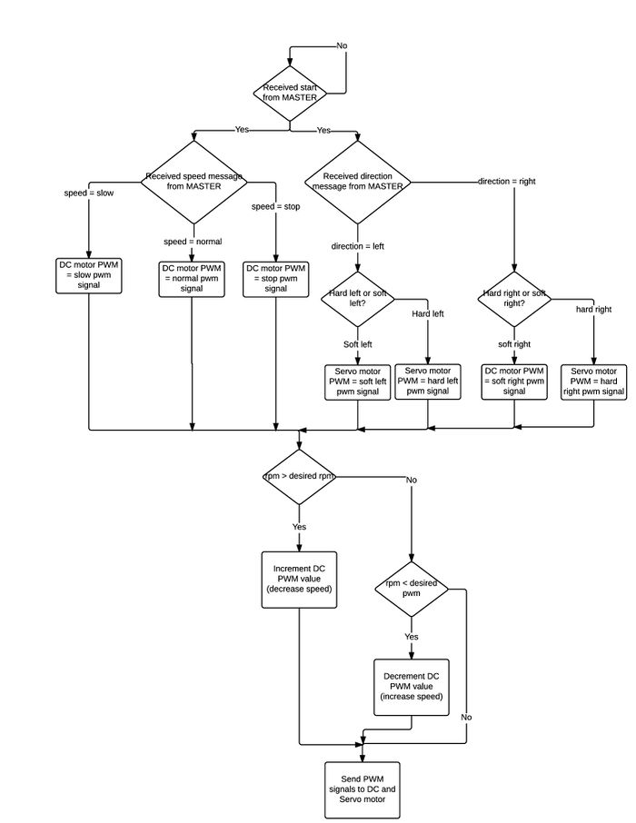
Software Flow Diagram
Speed Feedback Encoder
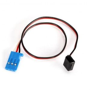
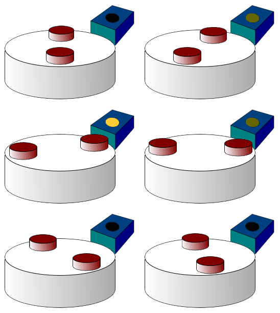
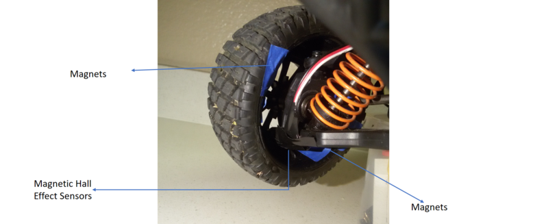
The speed feedback is simply an RPM meter. It consists of a Hall Effect Magnetic sensor with a set of magnets. The magnets are attached to the inner surface of the wheels and the sensor is connected to the end of the shaft connecting the wheel. Whenever the magnet comes near the sensor, a high signal is generated from the sensor and given to the GPIO port of the SJOne board, which is made as positive edge triggered. The interrupt handler would then increment a count which would give us revolutions per second if the above mentioned count is measured over one second (1Hz periodic callback function).
The next step is to control the speed with this calculated rpm. There are two conditions that need to be checked. One is the speed that the MASTER controller is sending (stop, slow, normal or fast) and another is the rpm. Each of the speeds would have a desired rpm and the calculated rpm is compared to the desired rpm and the final PWM signal to the DC motor is incremented or decremented depending on that. A scenario for this usage would be when the car encounters an upward ramp and the car would slow down while climbing to that. The algorithm would check and sense that the rpm has reduced and would modify PWM for DC to increase power and hence the RPM of car is kept at the desired range.
Liquid Crystal Display
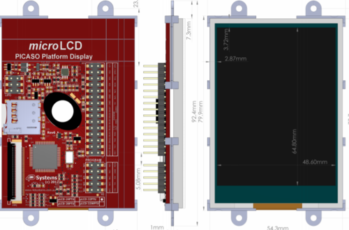
IO is the mode of interaction between user and car peripherals. LCD displays the car status while the touch screen allows the user to shift between the various modes. The touch screen GLCD uLCD32PTU has the following features Low-cost 3.2" LCD-TFT display graphics user interface solution. 240 x 320 VGA resolution, RGB 65K true to life colours, TFT screen with Integrated 4-Wire Resistive Touch Panel. Easy 5 pin interface to any host device: VCC, TX, RX, GND, RESET Powered by 4D-Labs PICASO processor. 2 x Asynchronous hardware serial ports (COM0, COM1), TTL interface, with 300 to 600K baud. On-board micro-SD memory card adaptor for multimedia storage and data logging purposes. HC memory card support is also available for cards larger than 4GB. 4.0V to 5.5V range operation (single supply).
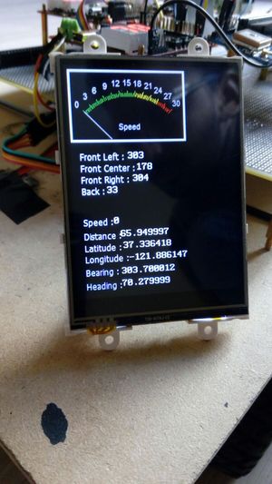
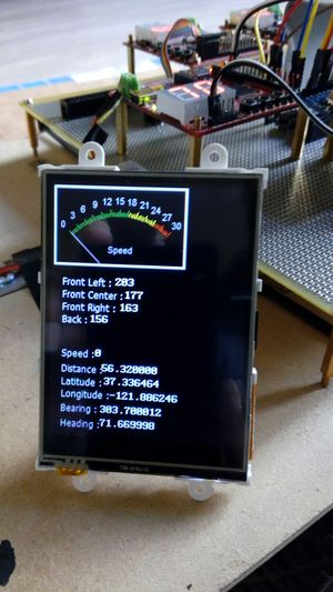
The LCD is used to display vital parameters such as
- Speed
- Sensor Readings
- Obstacle proximity
- GPS co-ordinates
- Current and heading compass zone
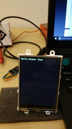
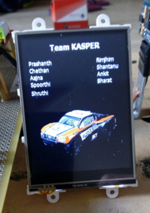
Shown below are some of the LCD screens created.
Testing & Technical Challenges
Issue 1: DC motor not responding to PWM signals given to ESC
Even though the PWM signals that were generated from the SJOne board were identical to those generated by the company issued remote control of the car (simulated and checked using the CRO), the DC motor was still not responding to the signals.
Solution: Create the PWM objects just once and never destroy them
This solution, obtained after much research online, was implemented using a singleton class which would be used to declare the PWM objects to pass the signal values and would hence declare the PWM objects only one and never be destroyed or re-initialized. It is essential to understand Pulse width Modulation.
Issue 2: Car Reversing on giving Forward Pulse.
We observed that initially after turning on the ESC, sometimes the car would go reverse on providing the forward pulse.
Solution:Provide the car a STOP pulse for around 20ms in the Init function of the Periodic scheduler.
This solution helps in the calibration of the ESC. Based on the initial pulse received, the ESC is calibrated. Any delay in switching on the ESC and resetting the SJ ONE board, may lead to the Reverse issue. Hence, the ESC had to be switched on simultaneously while resetting the SJ ONE board. This eliminated the unwanted reverse.
Issue 3: Erratic readings while using the Light Sensor for Motor feedback.
Initially we used the Light sensor to measure the RPM of the car. This was done by taping a white patch on to the front wheel of the car and the sensor was placed just above the wheel. Light sensor should not be used for Motor Feedback purpose since the Light readings were erratic.
Solution:Use Magnetic Hall Effect sensors.
Using the magnetic sensors eliminated the erratic readings. One tricky part is that the sensors need to be mounted really close to the magnets. It is essential to test the car on different terrains and observe if the car is able to move without any difficulty.
Geographical Controller
Team Members & Responsibilities
- Ankit Gandhi
GPS, Compass firmware and Hardware Interfacing.
Schedule
| SI No. | Start Date | End Date | Task | Status | Actual Completion Date |
|---|---|---|---|---|---|
| 1 | 09/28/2016 | 10/4/2016 |
|
Complete | 10/6/2016 |
| 3 | 10/5/2016 | 10/11/2016 |
|
Complete | 10/10/2016 |
| 4 | 10/12/2016 | 10/18/2016 |
|
Complete | 10/18/2016 |
| 5 | 10/19/2016 | 10/25/2016 |
|
Complete | 10/26/2016 |
| 6 | 10/26/2016 | 11/01/2016 |
|
Complete | 11/02/2016 |
| 7 | 11/02/2016 | 11/08/2016 |
|
Complete | 11/09/2016 |
| 8 | 11/09/2016 | 12/05/2016 |
|
Complete | 12/11/2016 |
Design & Implementation
Hardware Design
Components
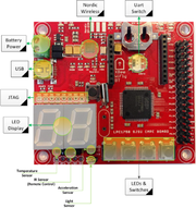
SJOne Board
The breakout is built around the MTK3339 chipset, a no-nonsense, high-quality GPS module that can track up to 22 satellites on 66 channels
- 512K ROM, 64K(96K) RAM, 1M(2M) SPI Flash, and Micro-SD for storage.
- Arm Cortex-M4 variant contains 96K RAM, and 2Mb SPI flash
- 2-Digit 7-Segment Display
- Power from USB or External Power
- Many GPIOs with two SPI, Multiple UARTs, and I2C and CAN availability
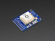
GPS Module
The breakout is built around the MTK3339 chipset, a no-nonsense, high-quality GPS module that can track up to 22 satellites on 66 channels
- -165 dBm sensitivity, 10 Hz updates, 66 channels
- 5V friendly design and only 20mA current draw
- RTC battery-compatible
- Internal patch antenna + u.FL connector for external active antenna
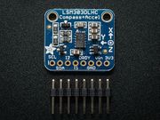
The Compass Module - LSM303DLHC
Compass module is based on ST Micros LSM303. When current flows through a wire, a magnetic field is created. This is the basic principle behind electromagnets. This is also the principle used to measure magnetic fields with a magnetometer. The direction of Earth's magnetic fields affects the flow of electrons in the sensor, and those changes in current can be measured and calculated to derive a compass heading.
The features of LSM303DLHCare:
- Simple I2C interface
- 3 magnetic field channels and 3 acceleration channels
- ±2g/±4g/±8g/±16g linear acceleration full scale
- From ±1.3 to ±8.1 gauss magnetic field full scale
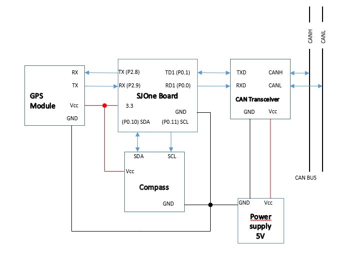
Following is the Geo Controller system diagram
Hardware Interface
Below table lists all the hardware pins used in Geo Controller
| Device Description | Bus | Device Pins | SJOne Board Pins |
|---|---|---|---|
| MCP2551 CAN Transceiver | CAN1 |
RD TD Vcc GND |
RD1 P0.0 TD1 P0.1 5V GND |
| GPS Module | UART2 |
Rx Tx Vcc GND |
TXD2 P2.8 RXD2 P2.9 5V GND |
| Compass | I2C2 |
SDA SCL Vcc GND |
SDA2 P0.10 SCL2 P0.11 Vcc GND |
Software Design
- Initialization
- GPS module is interfaced using UART. UART is initialized using the most common configuration 9600/8-N-1(9600 baudrate, 8 databits, no (N) parity bit, and :one (1) stop bit.
- We are using LSM303DLHC compass module. Both GPS and Compass modules are initialized as below.
 void geotaskInit()
 {
     gpsUart.init(GPS_BAUD_RATE,rx_q,tx_q);   // Initialize UART for GPS
     LSM_MAG.init();                          // Initialize LSM303 Magnetometer
     LSM_ACCL.init();                         // Initialize LSM303 Accelerometer
 }
- Data Communication with GPS and Compass
GPS
- GPS module is programmed to send GPS data at 10Hz. Interrupt Handler continuously receives these data and stores in the queue.
- Periodically (10Hz) calling the getChar function gives a complete NMEA string.
- Following string is used to set NMEA output sentence, we are using GPRMC for this project(Done in initialization)
char gpsRMConlyCommand[] = "$PMTK314,0,1,0,0,0,0,0,0,0,0,0,0,0,0,0,0,0,0,0*29\r\n";
char gpsOutputFrequency[] =  "$PMTK220,100*2F\r\n";
- After sending this, we will be getting GPS string after every 10Hz, which is read by interrupt handler.
Compass
- Compass data is read and send every 10Hz. Compass data consists of Bearing, Distance and Heading
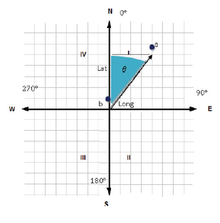
- Bearing Calculation:
- Bearing angle between two GEO coordinates is calculated using following formula
θ = atan2( sin Δλ ⋅ cos φ2 , cos φ1 ⋅ sin φ2 − sin φ1 ⋅ cos φ2 ⋅ cos Δλ )
  where, φ1,λ1 is the start point
  φ2,λ2 the end point
  (Δλ is the difference in longitude)
- Distance Calculation:
- Distance between two GEO coordinates is calculated using following formula
a = sin²(Δφ/2) + cos φ1 ⋅ cos φ2 ⋅ sin²(Δλ/2)
c = 2 ⋅ atan2( √a, √(1−a) )
d = R ⋅ c
  where φ is latitude, λ is longitude,
  R is earth’s radius (mean radius = 6,371km);
- CAN Communication
- In GeoController, we are using can1 for transmitting and receiving can messages. Latitude and longitude values are getting updated periodically.
  void geoTask::sendGpsData()
  {
      if(recvdTrueGPSData == true)
      {
          GPS_LOCATION_t geoGpsData = { 0 };
          geoGpsData.GPS_LOCATION_latitude = curLatitude;
          geoGpsData.GPS_LOCATION_longitude = curLongitude;
          u0_dbg_printf("lat : %f lon: %f\n",curLatitude,curLongitude);
          // This function will encode the CAN data bytes, and send the CAN msg using dbc_app_send_can_msg()
          dbc_encode_and_send_GPS_LOCATION(&geoGpsData);
          recvdTrueGPSData = false;
      }
   }
  void geoTask::sendCompassData()
  {
      COMPASS_DATA_t geoCompassData = { 0 };
      calculateDistance();
      if(newChkPointRecvd)
      {
          calculateBearing();
          newChkPointRecvd = false;
      }
      LSM_MAG.getHeading(&heading);
      geoCompassData.COMPASS_DATA_bearing = bearing;
      geoCompassData.COMPASS_DATA_heading = heading;
      geoCompassData.COMPASS_DATA_speed = speed;
      geoCompassData.COMPASS_DATA_distance = distance;
      u0_dbg_printf("head: %f,bearing:%f,Dis:%.2f\n",heading,bearing,distance);
      // This function will encode the CAN data bytes, and send the CAN msg using dbc_app_send_can_msg()
      dbc_encode_and_send_COMPASS_DATA(&geoCompassData);
   }
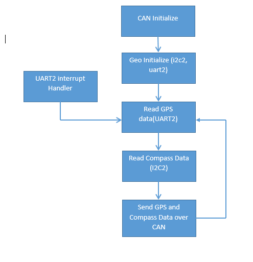
Geo Software Flow Diagram
Testing & Technical Challenges
1. Compass Calibration
Initially compass doesn't give correct readings,compass needs to be calibrated before it can be used. -->Used following Arduino sketch to get the minimum and maximum readings of the compass on all three axes.
void loop()
{
   compass.read();
   running_min.x = min(running_min.x, compass.m.x);
   running_min.y = min(running_min.y, compass.m.y);
   running_min.z = min(running_min.z, compass.m.z);
   running_max.x = max(running_max.x, compass.m.x);
   running_max.y = max(running_max.y, compass.m.y);
   running_max.z = max(running_max.z, compass.m.z);
   snprintf(report, sizeof(report), "min: {%+6d, %+6d, %+6d}    max: {%+6d, %+6d, %+6d}",
   running_min.x, running_min.y, running_min.z,
   running_max.x, running_max.y, running_max.z);
   Serial.println(report);
   delay(100);
}
Use of these Minimum and Maximum Values in the calculation gives better readings
Another issue with compass is tilt compensation. If compass is tilted it gives wrong readings. Tilt needs to be compensated using Accelerometer readings.
pitch = asin(-accxnorm);
roll = asin(accynorm/cos(pitch));
where accxnorm and accynorm are normalized x and y acceleration vector respectively.
Communication Bridge Controller
Team Members & Responsibilities
- Bharat Khanna
- Shantanu Vashishtha
Schedule
| SI No. | Start Date | End Date | Task | Status | Actual Completion Date |
|---|---|---|---|---|---|
| 1 | 09/20/2016 | 09/27/2016 |
|
Complete | 09/27/2016 |
| 2 | 09/28/2016 | 10/4/2016 |
|
Complete | 10/9/2016 |
| 3 | 10/5/2016 | 10/11/2016 |
|
Complete | 10/11/2016 |
| 4 | 10/12/2016 | 10/18/2016 |
|
Complete | 10/18/2016 |
| 5 | 10/19/2016 | 10/25/2016 |
|
Complete | 10/25/2016 |
| 6 | 10/26/2016 | 11/08/2016 |
|
Complete | 11/08/2016 |
| 7 | 11/9/2016 | 11/20/2016 |
|
Complete | 11/20/2016 |
| 8 | 11/21/2016 | 12/05/2016 |
|
Complete | 12/18/2016 |
Design & Implementation
The design section can go over your hardware and software design. Organize this section using sub-sections that go over your design and implementation.
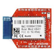
Bluetooth Module
RN42XV is built around Microchip's RN42 low power Bluetooth module. Some features of this module are as follows
- Based on the popular 2 x 10 (2mm) socket footprint.
- Voltage range: (3-3.6)Volts
- Current range: 26 μA sleep, 3 mA connected, 30 mA transmit.
- UART data connection interface.
- Sustained data rates: 240 Kbps (slave), 300 Kbps (master)
- Transmission range up to 60 feet (20 m) distance, +4 dBm output transmitter, -80 dBm typical receive sensitivity.
- FHSS/GFSK modulation, 79 channels at 1-MHz intervals.
Hardware Design
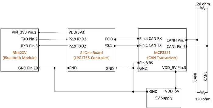
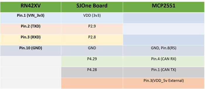
The interface between Bluetooth module and controller is as shown in figHardware Interface
The interface between Bluetooth module and controller is as shown in fig The interface between Bluetooth module and controller is as shown in figBluetooth Software Design
The main functions that are used for communication are as follows.
void Check_Start_STOP__CheckPoint_Condition()
{
	if(strcmp(stored_Bluetooth_data,START) == 0)
	{
		START_CONDITION.START_CMD_APP_data = 1;
		dbc_encode_and_send_START_CMD_APP(&START_CONDITION);
		memset(stored_Bluetooth_data, 0, sizeof(stored_Bluetooth_data));
	}
	else if(strcmp(stored_Bluetooth_data,STOP) == 0)
	{
		STOP_CONDITION.STOP_CMD_APP_data = 1;
		dbc_encode_and_send_STOP_CMD_APP(&STOP_CONDITION);
		memset(stored_Bluetooth_data, 0, sizeof(stored_Bluetooth_data));
	}
	else if(check_received == true)
	{
		int loop =0;
		BRIDGE_TOTAL_CHECKPOINT.BRIDGE_TOTAL_CHECKPOINT_NUMBER = check_point_total;
		dbc_encode_and_send_BRIDGE_TOTAL_CHECKPOINT(&BRIDGE_TOTAL_CHECKPOINT);
		for(loop = 0; loop < (check_point_total*2) ;loop=loop+2)
 		{
			BLUETOOTH_DATA_Location.BLUETOOTH_DATA_LAT = store_cor[loop];
			BLUETOOTH_DATA_Location.BLUETOOTH_DATA_LON = store_cor[loop+1];
			dbc_encode_and_send_BLUETOOTH_DATA(&BLUETOOTH_DATA_Location);
		}
		check_received = false;
	}
 }
void Can_Receive_ID_Task()
{
	if (CAN_rx(can1, &can_msg_Info, 0))
	{
		LE.off(1);
		dbc_msg_hdr_t can_msg_hdr;
		can_msg_hdr.dlc = can_msg_Info.frame_fields.data_len;
		can_msg_hdr.mid = can_msg_Info.msg_id;
		if(can_msg_Info.msg_id == RESET_HDR.mid)
			dbc_decode_RESET(&REST_Info, can_msg_Info.data.bytes, &can_msg_hdr);
		if(can_msg_Info.msg_id == RECEIVE_START_ACK_HDR.mid)
			printf("Case_RECEIVE_START_ACKt\n");
		if(can_msg_Info.msg_id == BRIDGE_POWER_SYNC_HDR.mid)
			printf("BRIDGE_POWER_SYNC_data\n");
		if(can_msg_Info.msg_id == GPS_LOCATION_HDR.mid)
		{
			dbc_decode_GPS_LOCATION(&GPS_LOCATION_RECEIVE, can_msg_Info.data.bytes, &can_msg_hdr);
			sprintf(lat,"%f",GPS_LOCATION_RECEIVE.GPS_LOCATION_latitude);
			sprintf(lon,"%f",GPS_LOCATION_RECEIVE.GPS_LOCATION_longitude);
		        Send_App_curr_loc(lat,lon);
		}
		if(dbc_handle_mia_RESET(&REST_Info, 1))
		{
			REST_Info.RESET_data=RESET__MIA_MSG.RESET_data;
			LD.setNumber(REST_Info.RESET_data);
			LE.on(1);
		}
	}
}
The interface between Bluetooth module and controller is as shown in fig
Implementation
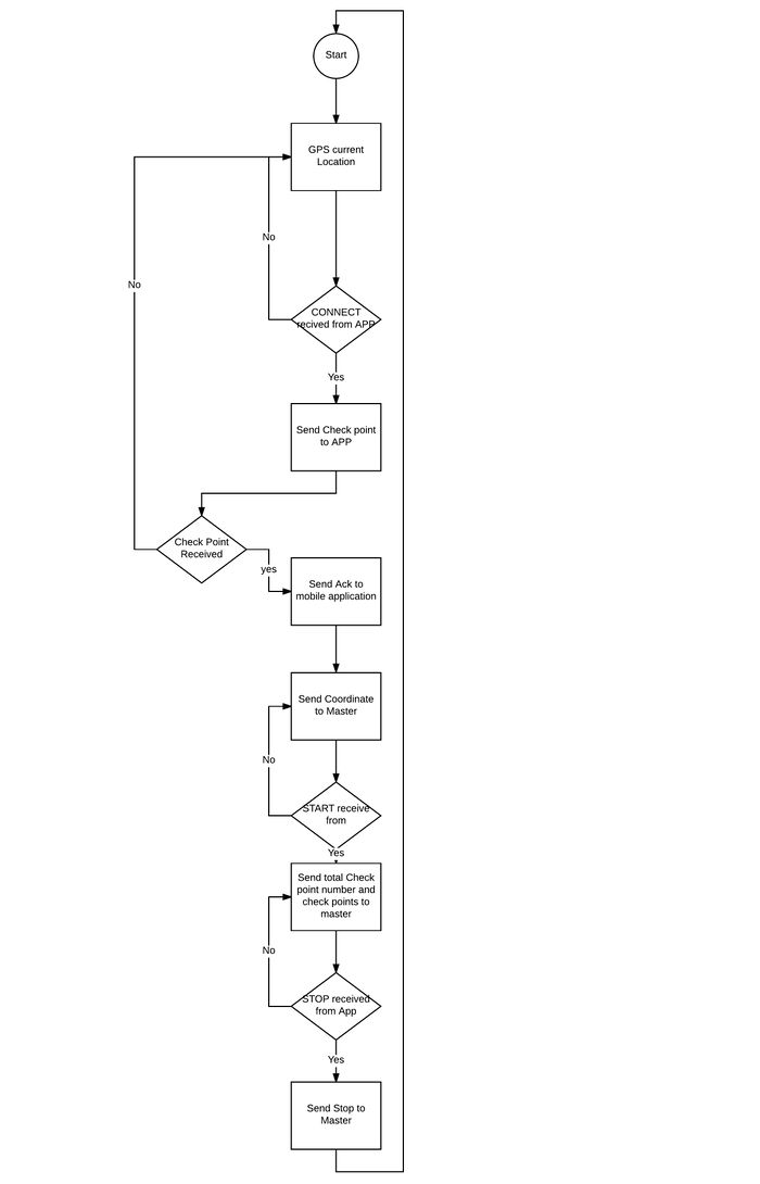
The aim of the project is the design and development of an autonomous vehicle which should be able to traverse from its current location to the destination provided by the user. The destination is provided by the user via Android mobile application. The bridge controller refers to communication between the master controller and the mobile application which is established using RN42XV Bluetooth module. The data that is received via mobile application is start command, stop command, total number of checkpoints and checkpoints itself. The SJOne boards establishes communication with Bluetooth module using UART communication protocol. Once the data is received by the Bluetooth controller it is then sent to the master controller using CAN communication protocol.
Android Application Design
Problem statement
In present day, what is that one thing, which has become an essential part of a human life? Yes, that's correct, the answer is smartphone. It is almost impossible to imagine a single day without a mobile phone. So whether it is for a bank transaction or daily grocery shopping or travel, we need all the updated information in our hand. Keeping in mind this technological need, an application to control and track our self driving car prototype makes total sense. With universality of android platform, we decide to make an adnroid application to control our self driving car prototype "Kasper".
Implementation
The objective of the Android application is to allow the user to communicate with the self driving car using a smartphone. The application is built using Android Studio. It is the official IDE for Android platform development. The project uses .java file to design the logic of the app. To integrate maps within your application, an API key from Google's developer console is required. This API helps Google in tracking the statistics related to the app. When a device is clicked, map pops up which means that map fragment has been successfully implemented. Application uses Android Application framework (API level 25). There are four activities responsible for complete functionality of the application, namely FirstActivity.java, MapActivity.java and LatLong.java.
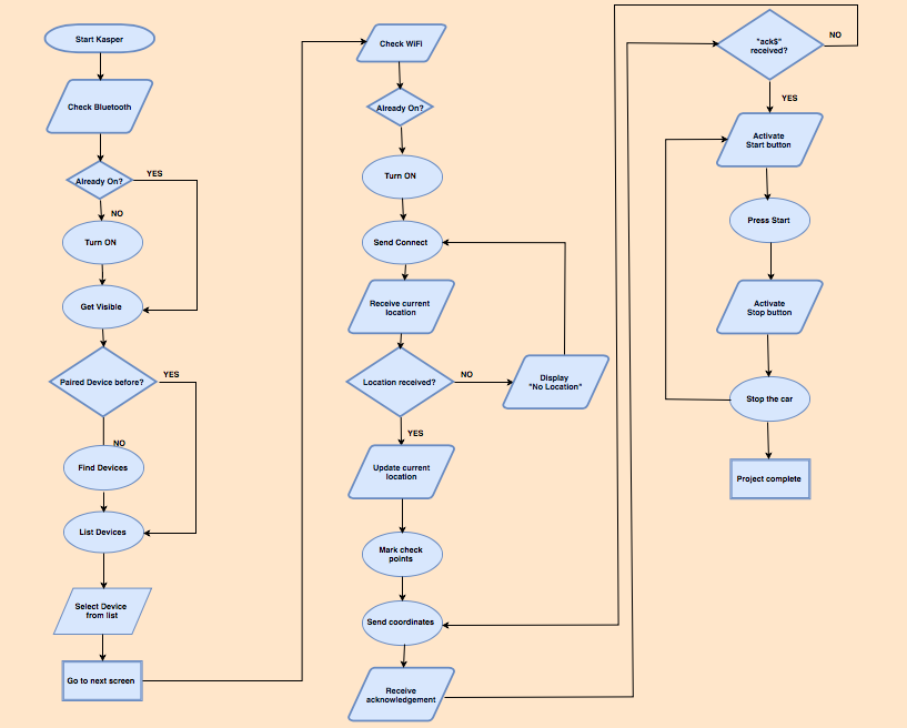
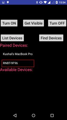
1. FirstActivity.java is responsible for screen 1 and has some basic buttons to "Turn ON" bluetooth for the device, find available bluetooth devices, make the smartphone discoverable to other devices, list paired devices and "Turn OFF" bluetooth on the device. After selecting an appropriate bluetooth module listed in the paired devices/available devices list, application makes a transition to screen 2.
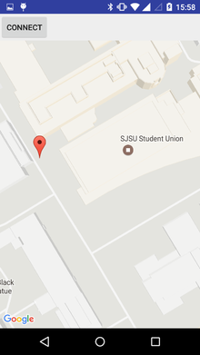
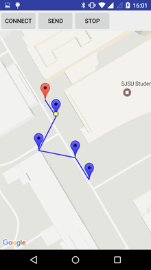
2. The most basic information that a user must be able to control in a self-driving car is the source and the destination. The source in the application is designed to set with the current location sent by GPS module to bluetooth controller.
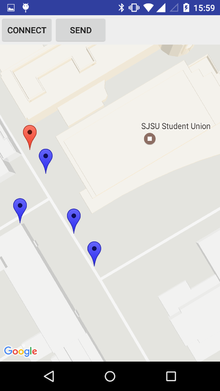
Screen 2 is controlled by MapActivity.java that opens a map. This file is responsible for creating a bluetooth socket that allows communication between the app and the actual hardware. After the map is visible, destination is marked manually by the user, by selecting a point on the integrated Google map API. The format of the point selection is such that the application will consider the final/last checkpoint as destination while the rest markers will be considered as intermediate checkpoints. Once the user is done marking the check points, the information is sent to Bluetooth controller in the following format:
n,latitude_1,longitude_1...latitude_n,longitude_n
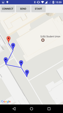
Here, n is number of checkpoints and (latitude_n,longitude_n) will be considered as the destination points by the Bluetooth controller. Once this information is sent, application waits for an acknowldgement in the form of "ack$" from the Bluetooth controller to ensure that the coordinates have been received. If there is no acknowldgement then the start button will not become active. After receiving acknowledgement, start button becomes active and the car will start moving when the button is asserted. Also, at a time only one of the two start or stop button is active. So, once a start button is pushed it is deactivated and stop is active now.
MapActivity.java also includes a handler for receiving messages like current location and then updating them on the map. It also receives coordinates at regular intervals to track the car location.
3. LatLong.java file has a public class with variables and methods that can used anywhere. This is done to set and get the latitude and longitude values.
Bluetooth - Android Interface
Command format and functionality
| SI No. | Button | Description | Screen | Command format |
|---|---|---|---|---|
| 1 | Turn ON | When this button is pressed it will ask user to turn ON the bluetooth.
If the bluetooth is already on then it will display "Already on" message. |
Screen 1 | -- |
| 2 | Turn OFF | When this button is pressed it will send a command to hardware to disable the bluetooth. | Screen 1 | -- |
| 3 | Get Visible | When this button is pressed it will ask user to make bluetooth device visible to other devices for 120 seconds. | Screen 1 | -- |
| 4 | List Devices | When this button is pressed it will display all the previously paired devices in a list view on the screen. | Screen 1 | -- |
| 5 | Find Devices | If the intended device is not in the List Devices list then press this button to search for available devices and then connect. | Screen 1 | -- |
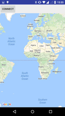
| 6 | Connect | When this button is pressed it will update the map with the current location sent by the GPS module to the Bluetooth controller. | Screen 2 |
|
| 7 | Send | After configuring the checkpoints, this button is used to send the coordinates of the selected points. | Screen 2 |
|
| 8 | Updating car location | The car location can be tracked depending upon the GPS data. | Screen 2 |
|
| 9 | Start/Stop | At a time only one of the button is active. Start will run the car while Stop will stop the car. | Screen 2 |
|
Application workflow
Application features
Android application has major features that exploit real time data. Once the phone is connected to the bluetooth module application starts sending and receiving data to perform number of operations. Features are listed below:
1. First feature is to get the current location. Application sends a command to request bluetooth module for updating the current location. After receiving the current location coordinates, application updates them on the Google map API used.
2. Second remarkable feature is updating the map with destination along with check points. This feature is highly desirable as it maps real life situation, in which destination is not reached instantly, but going from one checkpoint to another. Once the checkpoint have been marked they are sent to the master controller.
3. Third feature provide a layer of reliability during communication. Once the checkpoints have been sent, start car button will not become active until there is an acknowldgement from the bluetooth controller that it has received the destination coordinates along with checkpoints. This ensures that the car will not go to any random location.
4. The fourth most important feature in the application is that it exploits the real time data sent by the GPS module. As the car starts moving, GPS coordinates change. This new data is received by the application that helps in tracking the current car location. This feature is extremely useful to trace the route that is taken by the car (if there is any obstacle in the initial path).
Android UI design
Testing
- For testing purpose, the code is made modular which means that each functionality in the code is defined in different functions. This approach makes it easier to check the output at different levels, which makes it easier to verify the output at different levels.
- The testing for Bluetooth module is done using "Bluetooth Serial Terminal" Application
Technical Challenges
- Technical challenge faced while communicating between Android app and Bluetooth was sending the current location which is achieved by updating the send_cor_buffer after every 10 milliseconds and sending updated coordinates.
Master Controller
Team Members & Responsibilities
- Aajna Karki
- Spoorthi Mysore Shivakumar
Schedule
| SI No. | Start Date | End Date | Task | Status | Actual Completion Date |
|---|---|---|---|---|---|
| 1 | 09/26/2016 | 10/05/2016 |
|
Complete | 10/05/2016 |
| 2 | 10/06/2016 | 10/18/2016 |
|
Complete | 10/18/2016 |
| 3 | 10/19/2016 | 10/25/2016 |
|
Complete | 10/25/2016 |
| 4 | 10/26/2016 | 11/07/2016 |
|
Complete | 11/07/2016 |
| 5 | 11/08/2016 | 11/15/2016 |
|
Complete | 11/20/2016 |
| 6 | 11/16/2016 | 11/29/2016 |
|
Complete | 11/29/2016 |
| 7 | 11/29/2016 | 12/06/2016 |
|
Complete | 12/12/2015 |
| 8 | 12/06/2016 | 12/15/2016 |
|
Complete | 12/18/2016 |
Design & Implementation
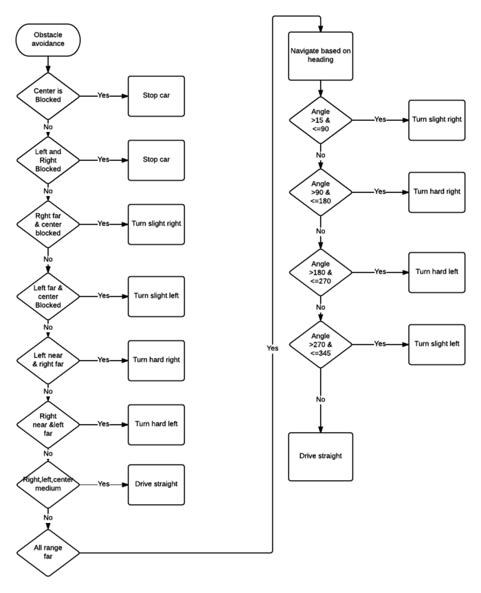
The Master Controller is responsible for driving the car based on the Obstacle Avoidance and Navigation algorithm.
Obstacle avoidance algorithm uses the sensor data and drives the motor accordingly. Navigation algorithm uses the data from compass to adjust the direction of the car based on the destination.
Hardware Design
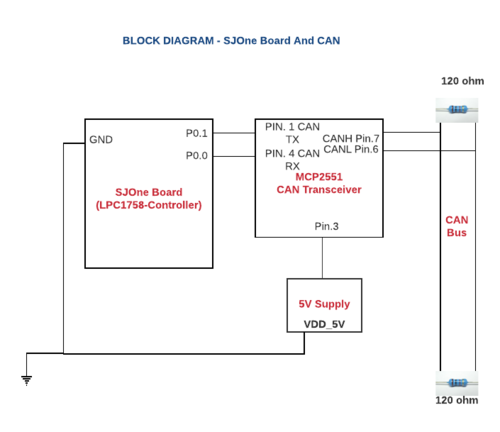
Master Controller is interfaced to CAN transceiver as shown below.
CAN messages are transmitted and received over the bus establishing communication with the rest of the controllers.
Hardware Interface
Master Controller is concerned with the implementation of algorithms to drive the car.
The hardware interface is only to the CAN transceiver over which communication with the rest of the controllers happens.
Software Design
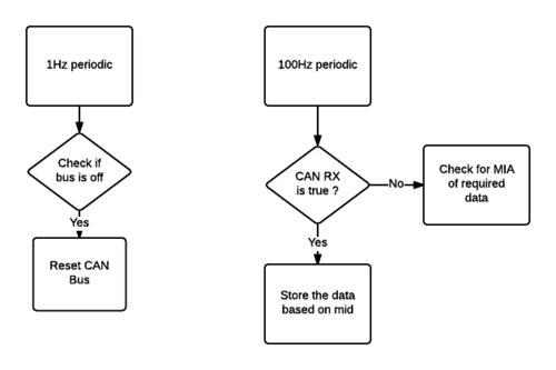
Master Controller receives CAN messages in the 100Hz periodic function.
The functionality to drive the car based on Obstacle Avoidance and Navigation Algorithm is implemented in the 10Hz periodic function.
The 1Hz periodic function implements the logic to check if CAN bus is on/off.
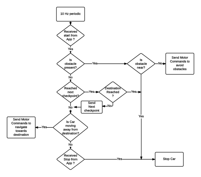
The drive commands to the car are based on the Obstacle Avoidance and the Navigation algorithm.
Obstacle avoidance is given priority over Navigation Algorithm.
If no obstacles are encountered, the control falls to the Navigation algorithm which directs the car to the destination.
Obstacle Avoidance Algorithm:
Three zones are declared based on the distance of the obstacle - NEAR zone, MEDIUM zone and FAR zone.
Based on which zone the obstacle is encountered in, appropriate decisions are made to drive the car.
Navigation Algorithm:
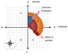
The compass readings obtained range from 0 to 360. Based on the readings, the data is divided into quadrants. Based on each of the value received, appropriate drive decisions are made.
Navigation Algorithm has lower priority as compared to Obstacle Avoidance algorithm.
Below is the detailed flowchart of Obstacle and Navigation Algorithm
Implementation
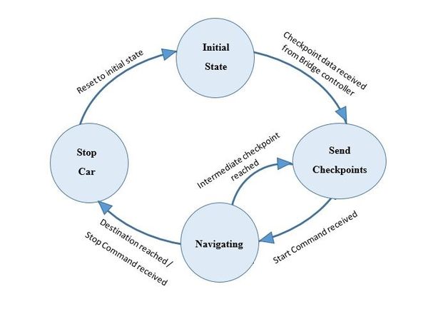
The overall function of the Master Controller can be visualized through the following state machines:
Initial State
This is the initial state of the car when no commands are received. The car is dormant at this point.
Send Checkpoints
Once the checkpoint data is received from the Bridge controller, it is saved in an array.
The checkpoints need to be sent to Geo controller sequentially. As and when a particular checkpoint is reached, next checkpoint data needs to be sent.
The state of the controller in which checkpoint data is sent constitutes this state.
Navigating
Navigation is started only after the Start command is received from the Bridge Controller.
When a CAN message with the Start command is received, the state of the car is changed to Navigating.
Stop Car
When Stop command is received from the Bridge Controller, the state of the car is changed to Stop Car.
Motor commands are sent to stop the car.
In terms of coding, they are defined as enum values:
enum STATE_CAR{
	SEND_CHECKPOINTS,
	NAVIGATING,
	STOP_CAR,
	INITIAL_STATE
};
Testing & Technical Challenges
Few challenges faced during the phase of the project are as below:
CAN Receive function
It is advisable that the system has only one CAN Receive. The values can be be populated in 100Hz and used in 1Hz/10Hz based on priority. Having more than one CAN receive can result in messages being missed.
When reading messages in 100Hz , an 'if' instead of 'while' could be used so that there is no task overrun.
Conclusion
The self driving car project has definitely helped us learn and grow in terms of technical knowledge as well as team management. Right from choosing the hardware components by considering every aspect of its functionality to programming them, this project has indeed given us an end-to-end learning of the entire system. There has been a lot of decision making which has resulted in many brain-storming sessions with the team as a whole.
The different phases of the project have been significant in their own terms. Selection of hardware is of utmost importance. We have had scenarios where we changed the ultrasonic sensors and the RPM sensors for greater accuracy. A major learning is that component selection needs diligent efforts. Sticking to the demo timelines would help a great deal. Code reviews would be beneficial as well.
We, as a team, have learnt how to build a machine from scratch. We also have learnt how a considerably big team can manage their particular modules and co-ordinate with the other modules as well. Team management has been a good takeaway here.
It has been overall a tremendous learning experience. I hope the further projects benefit from our learning curve documented.
Project Video
Other video links
- Obstacle Avoidance
- Sensor and LED blinking test
Project Source Code
References
Acknowledgement
This project has been an amazing learning experience for the whole team. The knowledge we take from here is immense. We are grateful to Professor Preetpal Kang for his guidance and efforts towards making our learning commendable. Also, we would like to extend our sincere thanks to the ISA team for their continuous support. Here is a special mention to the Kasper team for all their meticulous and diligent efforts towards making this project a reality.
References Used
[1] Preetpal Kang's lecture notes of CMPE 243, Computer Engineering, San Jose State University, Aug-Dec 2016.
[2] Fall 2015 Wiki Projects
[3] LPC1758 User Manual
[4] Parallax Ultrasonic Sensor
[5] CAN Transceiver
[6] Razor IMU
[7] LSM303 Application Note
[8] Adafruit Ultimate GPS Breakout - 66 channel w/10 Hz updates - Version 3
[9] GPS data calculation accuracy
[10] GPS Longitude Latitude distance calculator
[11] Calculate distance between two points
[12] GLCD with Touchscreen
[13] GPS Datasheet
[14] CAN Communication
[15] Hall effect sensor
