Difference between revisions of "S16: Biker Assist"
Proj user13 (talk | contribs) (→Project Schedule) |
Proj user13 (talk | contribs) (→Project Schedule) |
||
| Line 118: | Line 118: | ||
! scope="row"| 8 | ! scope="row"| 8 | ||
| 05/19/2017 | | 05/19/2017 | ||
| − | | 05/ | + | | 05/23/2017 |
| − | | Final testing and Demo | + | | |
| − | | | + | *Final testing and Demo |
| − | | | + | | Not started |
| + | | | ||
|- | |- | ||
|} | |} | ||
Revision as of 07:13, 23 March 2017
Contents
- 1 Biker Assist
- 2 Abstract
- 3 Objectives & Introduction
- 4 Project Schedule
- 5 Parts List & Cost
- 6 Design & Implementation
- 7 Testing & Technical Challenges
- 8 Conclusion
- 9 Acknowledgement
- 10 References
Biker Assist
Abstract
There are 60 million bicyclists on the road in the United States and 500,000 emergency department visits are due to bicycle-related injuries. The Biker Assist system increases the safety of bicyclists by improving how the bicyclist communicates with the rest of the road. Currently, the only way a bicyclist can signal to another vehicle that they are making a turn is by extending their arm in that direction, we propose a better way to accomplish this by using lights on the back of the bicyclist. These lights operate seamlessly and automatically without any input from the bicyclist so that the bicyclist can keep his attention on the road. There are distance sensors on each side of the bicyclist that alert the bicyclist of any vehicles in their blind spot by using a simple text-to-speech system. Also, the headlights operate automatically, turning on only when it is night time and turning off during the day time, without any direct input from the user.
Objectives & Introduction
In today's world, everyone is moving towards building technologies which are wearable for a personalized user. In this project,we try and replicate this thought by providing a bike rider with a system that helps both the rider and the area where the rider is commuting to.
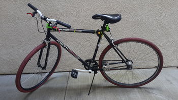
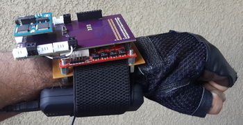
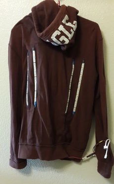
We mounted everything on a jacket and bike that acts as a wearable and can be easily removed.
Below are the functionalities that we have been able to implement:
- Obstacle detection using ultrasonic sensor
- Communication with Text-to-Speech module
- Interfacing with LED strips and SJOne board
- Design of PCB shield for the SJOne board
- Controlling front headlight using SJOne board's light sensor
Team Members
Roles and Responsibilities
- Adnan Dzebic & Nitesh Jain
- PCB Design
- LED Strip Design
- LED Strip Mounting/Hardware Integration
- Urvashi Agarwal & Amit Pachore
- Distance Sensor Design
- Turn Angle Sensor Design
- Text-to-Speech Module
- Hardware Designs
- 3D Designs
Project Schedule
| Sr. No. | Start Date | End Date | Task | Status | Actual Completion Date |
|---|---|---|---|---|---|
| 1 | 03/20/2017 | 03/26/2017 |
|
Completed | 03/26/2017 |
| 2 | 03/27/2017 | 04/02/2017 |
|
In progress | |
| 3 | 04/03/2017 | 04/09/2017 |
|
Not started | |
| 4 | 04/10/2017 | 04/16/2017 |
|
Not started | |
| 5 | 04/17/2017 | 04/27/2017 |
|
Not started | |
| 6 | 04/28/2017 | 05/04/2017 |
|
Not started | |
| 7 | 05/05/2017 | 05/18/2017 |
|
Not started | |
| 8 | 05/19/2017 | 05/23/2017 |
|
Not started |
Parts List & Cost
| Sr. No | Part Name | Source of Purchase | Part Number | Quantity | Cost($) |
|---|---|---|---|---|---|
| 1 | Distance Sensor | Maxbotix | MB1260 | 2 | 120.00 |
| 2 | Text to Speech Module | Adafruit | Emic 2 Text-to-Speech module | 1 | 65.00 |
| 3 | Hall Effect Sensor | Digikey | MLX90215 | 2 | 8.52 |
| 4 | Thinpot | Digikey | TSP-L-0050-103 | 2 | 10.12 |
| 5 | Wiper | Digikey | WP-M1-01-03-014-DI | 2 | 10.12 |
| 6 | Neopixel LED Strip | Amazon | ALITOVE LED Strip | 1 | 29.99 |
| 7 | LED Strip 2 | Amazon | RGB LED Strip | 2 | 30.00 |
| 8 | MOSFET | Excess Solutions | NTD5865N | 1 | 1.00 |
| 9 | Male Connector Wire Cable | Amazon | 5 pin Male Connector Wire Cable For Flexible RGB LED Strip | 1 | 8.99 |
| 10 | Hardware | Excess Solutions | Screws, Nuts, Bolts, Spacers | 10 | 5.00 |
| 11 | Miscellaneous | Excess Solutions | Connectors, Heat Shrink | 10 | 7.98 |
Design & Implementation
Overall System
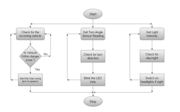
The overall system is divided into 3 parts:
1)Obstacle Alert: Based on the sensor readings, the rider can be alerted of the obstacles that are approaching from the behind. Here the values from the sensor are calculated and based on a suitable safety range,the rider is alerted by a voice.
2)Rider Alert:Based on the actions of the bike rider, the person from behind can be alerted. The turn direction sensor is hooked onto the bike's handle that is used to alert anyone from behind of the direction the biker took with the help of LED's attached on the back of a jacket.
3)Automatic Headlights: Based on the light sensor from the SJSUone Board, we control the main Headlight on the bike, to help the rider in dark.
All these functionalities work in parallel and have the same priorities that enable each system equal opportunity and time from micro-controller.
Overall System Flow
Printed Circuit Board
Design
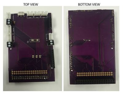
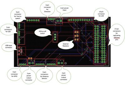
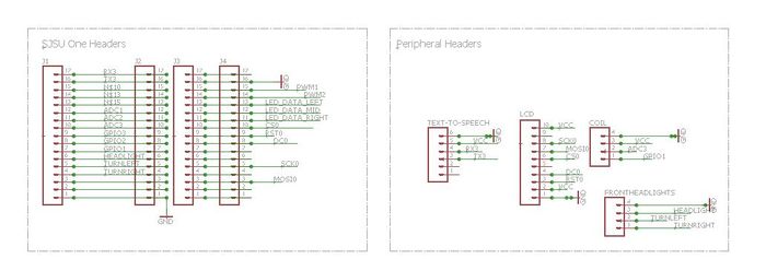
We designed a custom 10x5.5 inch PCB for our project where we integrated different modules together along with the SJSUone board. The PCB connects to the text to speech module, direction detection module, sensor module, LED’s and the SJSUone board. We replicated all the pins from SJSUone board also for further functionalities.
EAGLE PCB Design Tool
To Design our customized PCB, we used the EAGLE 7.5.0 Freeware tool. EAGLE stands for, Easily Applicable Graphical Layout Editor. EAGLE contains a schematic editor, for designing circuit diagrams. Parts can be placed on many sheets and connected together through ports. The PCB layout editor allows back annotation to the schematic and auto-routing to automatically connect traces based on the connections defined in the schematic. EAGLE saves Gerber and PostScript layout files and Excellon and Sieb & Meyer drill files. These standard files are accepted by many PCB fabrication companies.
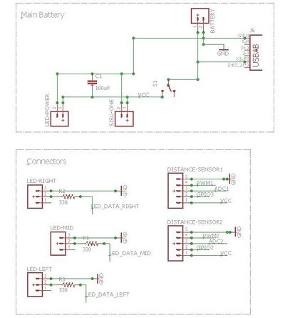
The tool provides us with many types of connectors and devices commonly used in PCB’s. Using a drag n drop methodology and by applying the connection internally, different ports can be joined. In our PCB design, we used a lot connectors with different pin configuration for different peripherals including 3-pin,4-pin,5-pin,10-pin and 17-pin connectors. Also we placed a switch for turning on-off the board. There are 2 power input sources: one is USB and second is normal power connector. To provide power to the various peripherals attached, we have 2 output power sources also. To maintain the integrity of the PCB, we grounded the unused area and unused pins from the PCB. Since we used a free tool, the max PCB size could only be 10inch x 5.5inch. The blue lines indicate the connection made from the bottom and red lines from the top. To avoid shorting of pin connections, we used through holes.
In order to design a PCB, we need to know the type of connectors to place. And to decide the type of connectors, we must know 3 things: Library, Package and Device name. Adafruit provides us with libraries that can be used for a variety of functions. Packages differentiate the type of connectors and Device defines the different types of connectors inside the Package that needs to be used. Below is a list of all the connectors that we used in this PCB and their library, package and device:
EAGLE Connector List
| Purpose | Connector Type | Library | Package | Device Name |
|---|---|---|---|---|
| Power | 3x2-pin | SparkFun-Connectors | SCREWTERMINAL-3.5MM-2 | M023.5MM (M02) |
| Power | USB | SparkFun-Connectors | USB-AB-MICRO-SMD_V03 | USB-ABCONN-11794 (USB-AB) |
| Power | Capacitors | SparkFun-Capacitors | 1206 | CAP1206(CAP) |
| SJSUone Board | 4x17-pin | SparkFun-Connectors | 1X17_NO_SILK | M17NOSILK (M17) |
| Text To Speech | 1x6-pin | SparkFun-Connectors | 1X06_NO_SILK | M06NO_SILK_FEMALE_PTH (M06) |
| Distance Sensors | 2x5-pin | SparkFun-Connectors | JST-5-PTH | M05JST (M05) |
| Direction Sensor | 1x4-pin | SparkFun-Connectors | JST-4-PTH | M04JST- PTH (M04) |
| Extra GPIO | 1x4-pin | SparkFun-Connectors | JST-4-PTH | M04JST- PTH (M04) |
| LED | 3x3-pin | SparkFun-Connectors | JST-3-PTH | M03JST- PTH (M03) |
| LCD | 1x10-pin | SparkFun-Connectors | 1x10_NO_SILK | M10NO_SILK_PTH_FEMALE (M10) |
Turn Angle Detection Sensor
Hardware Design
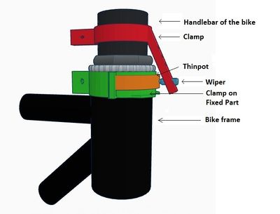
A turn angle detection sensor is used to detect the exact measure of turn of the bike handlebar. This angle measurement is used to determine if the bike is taking turns. This sensor design has two different approaches. These are varying resistance approach and hall effect approach. Finally, we settled on using thinpot which works on the varying resistance approach. These two methods are explained below.
Varying Resistance Sensor
This sensor functions using the principle of Ohm's law. This law dictates that the current is inversely proportional to resistance for a given voltage. The sensor has three terminals, two end points for connecting voltage across sensor and one middle terminal called wiper. As the wiper terminal traverse over the coil, sensor gives varying resistance across wiper and one of the other terminals and hence varying voltage. Varying voltage output pin is connected to the ADC of the micro-controller and exact turn angle can be determined. We worked on two different sensors working on this principle.
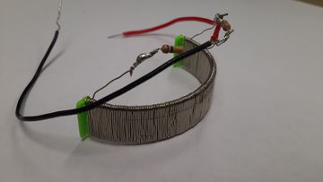
Custom Resistance Coil
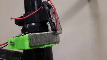
To detect turn angle, we designed our custom coil. We wound high resistance wire on a semicircular base to look like a coil. This coil was attached to the fixed part of the bicycle. The third terminal acting as a wiper was attached to the moving part of the handlebar such that, it traverses over the coil. We attached two resistances of value 10K were attached before connecting to the battery. These two circuits formed a potential divider circuit and also avoided battery short circuit.
Thinpot
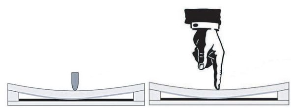
Thinpot is another sensor which is directly available in the market. It works on the same principle of variable resistance. It is nothing but the potentiometer which can be arced and pasted to curved surfaces. It has three terminals, two for supply, ground and one for measuring variable resistance. We have to use external wiper which traverse over the thinpot and resistance gets changed at pin 2 of the wiper. The total resistance of thinpot is 10KΩ which changes as wiper moves. We used this sensor as it has no restrictions over power supply voltage, easy to attach to bike, and easy to get readings using ADC.
Hall Effect Sensor
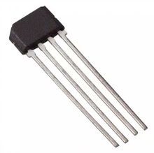
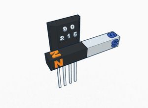
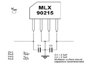
A Hall effect sensor is a sensor that varies its output voltage in response to a magnetic field. Hall effect sensors are used for proximity switching, positioning, speed detection, and current sensing applications. The sensor operates as an analog transducer, directly returning a voltage. There three types of hall effect sensors, hall effect switch, hall effect latch and hall effect linear sensor. Hall effect switch turns on in the presence of a magnetic field. Hall effect latch holds its current state until the opposite polarity changes its state. Hall effect linear sensor varies its output voltage in proportional to the strength of the magnetic field near to it. In the absence of magnetic field, linear sensor output voltage is approximately 2.5V. When the south pole comes closer to the sensor, its output increases proportionally towards 5V. Its output voltage decreases towards 0V, when north pole is brought closer to the sensor. We used this property to to detect the turn angle direction. We designed our sensor arrangement such that a horizontal bar magnet attached to the handlebar and sensor to the bike frame. When a magnet moves with handlebar while taking turns, the output of the sensor varies. But the sensor MLX90215 which we used for this testing was not behaving as per the design. Its EEPROM needed to be programmed irs special programmer. After some testing, we decided to change our design and switched to thinpot.
Software Design
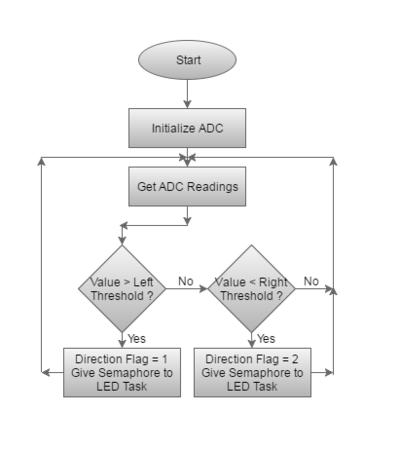
The high priority task is created for the turn detection and angle measurement. ADC drivers provided by the Preet are used to initialize and get readings. Once the direction is determined, LED_Semaphore is given to LED task to blink the LEDs.
Algorithm
- Initialize ADC
- Get Readings from the ADC
- Determine the direction form ADC value
- Give semaphore LED task with direction information
Flow Chart
Code Snippet
 /*Direction Detection*/

    ADC_reading = adc0_get_reading(4);
    if(ADC_reading>LEFT_DIR_THRESH)
    {
        Direction_flag = 1;
        xSemaphoreGive(LED_Semaphore);
    }
    else if(ADC_reading<RIGHT_DIR_THRESH)
    {
        Direction_flag = 2;
        xSemaphoreGive(LED_Semaphore);
    }
Object Detection Sensor
Hardware Design
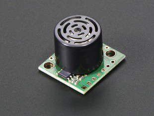
The distance sensors are used to detect the oncoming traffic from the back and to warn the rider about the traffic.The distance sensors' output will then be given to the voice module which will output the details to the biker in audio form.For the distance sensing we used the Maxbotix 1260 sensor.
Sensor Working
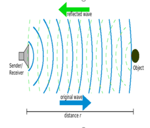
Maxbotix makes use of ultrasonic waves to sense the objects.The frequency used by these sensors in 42kHz sound waves.The frequency is selected
such that it is able to detect object regardless of its visual characteristics.The 42kHz frequency will not range through the solids.The main concept behind the ultrasonic sensors is that it sends the ultrasonic waves towards the objects.These waves when hit an object it gets reflected back from the object and the sensor sends an interrupt to the processor.
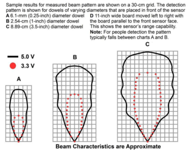
Bean Pattern
The sensor has a calibrated beam pattern.The diagram below shows the approximate beam pattern and the detection area.One can select the distance sensor matching their needs depending on the pattern and the range of the beam. The beam patterns help identify an estimated detection zone for an application based on the acoustic properties of a target versus the plotted beam patterns. Each beam pattern is a 2D representation of the detection area of the sensor. The beam pattern is actually shaped like a 3D cone (having the same detection pattern both vertically and horizontally).
Sensor Minimum Distance
The sensor minimum reported distance is 20cm (7.87 inches). However,the maxbotix ranges and reports targets to the front sensor face. Large targets closer than 20cm typically range as 20cm.
Software Design
The distance sensor task is the most important aspect of the project, and hence, it is a high priority task. The output of the sensor is interfaced with the text to speech module which will alert the user about the traffic.
Algorithm
- Initialize the sensor
- Wait for interrupt from the sensor
- Calculate the distance based on the calibration factor
- Give Semaphore to the Text to speech module based on sensor readings
Flowchart
Code Snippet
 /*Initialize Interrupt*/

    bool init()
    {
      Left_Tigger.setAsOutput();
      Left_PWM.setAsInput();
      Right_Trigger.setAsOutput();
      Right_PWM.setAsInput();
      const uint8_t port2_0 = 0,port2_1=1;
      eint3_enable_port2(port2_0,eint_rising_edge,Left_Sens_Rising_Int);
      eint3_enable_port2(port2_0,eint_falling_edge,Left_Sens_Falling_Int);
      eint3_enable_port2(port2_1,eint_rising_edge,Right_Sens_Rising_Int);
      eint3_enable_port2(port2_1,eint_falling_edge,Right_Sens_Falling_Int);
      lpc_timer_enable(lpc_timer0, 1);
      Left_Tigger.setLow();
      Right_Trigger.setLow();
      return true;
     }
 /*Interrupt handler to calculate distance*/

    void Left_Sens_Falling_Int()
 {
     sensor_value.left = (lpc_timer_get_value(lpc_timer0) - left_start_time)/58;
     next_trigger = 2;
     echo_received = 1;
     LE.off(1);
 }
 /*Give Semaphore based on distance*/

 if(echo_received)
  {
    count=0;
    echo_received = 0;
    if(sensor_value.right<DISTANCE_THRESHOLD)
    {
      SelectText = RightDirection;
      xSemaphoreGive(TTS_Semaphore);
    }
  }
 else if(sensor_value.left<DISTANCE_THRESHOLD)
  {
    SelectText = LeftDirection;
    xSemaphoreGive(TTS_Semaphore);
  }
LED Strip
Hardware Design
Neopixel LED Strip
The Neopixel LED strip, created by Adafruit, was the first LED solution that we looked at because of its popularity and because it is known to be easy to program. Adafruit provides libraries for the Arduino platform and we quickly set up an LED strip with an Arduino microcontroller. Our next goal was to convert the Arduino library code to the SJOne Board, but unfortunately we ran into multiple issues while trying to convert the code to the SJOne platform. The Neopixel uses a small IC called the WS2812b which is very sensitive to the data input that it receives and the datasheet leaves much to be desired in terms of describing the type of signal that is expected. Each LED contains a WS2812b IC and they are connected together in daisy chain fashion with each output of the current LED being connected to the input of the following LED. Near perfect timing is necessary for the WS2812b to function properly, which may be possible by using the SJOne Board's SPI peripheral and by "bit-banging" but we chose not to pursue that approach since we agreed that it was far more complex than it was worth. For that reason, we abandoned the Neopixel LED Strip in favor of a more suitable LED strip that works easily with the SJOne board.
RGB LED Strip
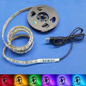
RGB LED strip is the simplest LED strip. It has four wires, Vcc, Red, Green, and Blue. Vcc is connected to the power supply, and other wires are connected the GPIO pins of the microcontroller. If any of the color lines is connected to the ground, then that color glows from the LED strip. For multiple colors, multiple lines are attached to the ground. This LED strip runs on 5V supply; hence, it can be directly connected to the microcontroller. Some LED uses 12V supply line. In this case, LED strip has to be connected to the microcontroller via MOSFET as a switch.
Software Design
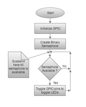
LED strip blinking for the turn indication is controlled using another LED_Blink_Task. A separate task is created to avoid the busy waiting while blinking the LEDs. This task gets signaled to run by the Turn Sensor Task using LED_Semaphore. If the task is not able to take the binary semaphore, then it suspends itself till somebody gives the semaphore. Simple GPIO drivers are for controlling the LED strip. If GPIO pin is made low, then the LED strip glows.
Algorithm
- Initialize GPIO pins
- Create binary semaphore LED_Semaphore
- If semaphore available, blink the LEDs as per the direction info by toggling GPIO pins
Flow Chart
Code Snippet
 /*Initialize GPIO and Create Binary Semaphore*/

        GPIO left_led(P2_2);
        GPIO right_led(P2_4);

        left_led.setAsOutput();
        left_led.setHigh();       //Set High to Turn off initially
        right_led.setAsOutput();
        right_led.setHigh();      //Set High to Turn off initially
        vSemaphoreCreateBinary(LED_Semaphore);
        xSemaphoreTake(LED_Semaphore,0);
 /*LED Blinking*/

        if(xSemaphoreTake(LED_Semaphore,portMAX_DELAY))
        {
            switch(Direction_flag)
            {
                case 1:
                    LE.toggle(3);
                    left_led.setLow();
                    vTaskDelay(1000);
                    left_led.setHigh();
                    vTaskDelay(1000);
                    Direction_flag = 0;
                    break;
                case 2:
                    LE.toggle(4);
                    right_led.setLow();
                    vTaskDelay(1000);
                    right_led.setHigh();
                    vTaskDelay(1000);
                   Direction_flag = 0;
                   break;
           }
        }
Text to Speech Module
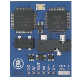
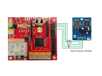
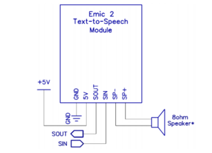
Emic 2 Text-to-Speech(TTS) module use UART protocol for the communication with the microcontroller. In this project, TTS module is connected to the SJone board over UART 3. This module has own commands for the text to speech conversion, voice selection, volume change, etc. It has onboard 3.5mm audio jack to which we connect any speaker or headphone. Its key features as listed on the adafruit.com are:
- High-quality speech synthesis for English and Spanish languages
- Nine pre-defined voice styles comprising male, female, and child
- Dynamic control of speech and voice characteristics, including pitch, speaking rate, and word emphasis
- Industry-standard DECtalk text-to-speech synthesizer engine (5.0.E1)
Hardware Design
Software Design
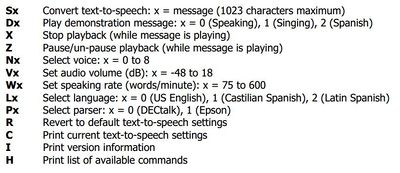
A separate high priority task is created to send the text to TTS module. This is task is waiting on the semaphore to send the text. The TTS_Semaphore is given by the distance sensor task when the distance is less than the set threshold. To control the TTS module different single characters are used as given in the beside image.
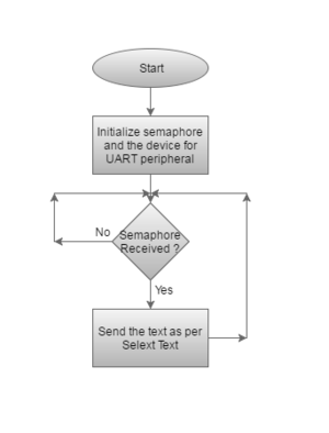
Algorithm
- Initialize the UART peripheral of the controller
- Create the binary semaphore to control the text to speech conversion
- Wait for the semaphore to be given
- Send the specific text to module using distance sensor data
Flow Chart
Code Snipppet
 /*Initialization*/

    tts_uart.init(TTSBaudRate,1,100);
    vSemaphoreCreateBinary(TTS_Semaphore);
    xSemaphoreTake(TTS_Semaphore,0);
    SelectText    = NoDirection;
/*Text Selection*/

    switch(SelectText)
    {
        case LeftDirection:
             tts_uart.putline("SCaution!Object on your Left! \n",portMAX_DELAY);
             tts_uart.getChar(&rec,0);
             break;
        case RightDirection:
             tts_uart.putline("SCaution!Object on your Right! \n",portMAX_DELAY);
             tts_uart.getChar(&rec,0);
             break;
        case NoDirection:
             break;
    }
    SelectText = NoDirection;
Headlight
Automatic headlight functionality is also implemented. This functionality reduces the overhead of turning in headlight manually. Using the light sensor value, the headlight is turned on when light intensity less than the threshold.
Hardware Design
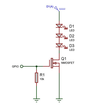
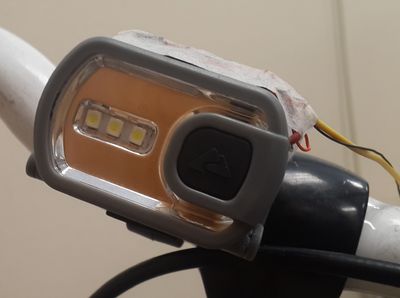
SJOne board has a light sensor installed on it. This light sensor is used to control the headlight mounted on the handlebar. Headlight has its own power supply for the LEDs in it. To control the headlight using SJOne board, we hacked the headlight and bypassed the switch. We have used MOSFET as a switch which can be controlled using the microcontroller. Detailed schematics is shown in the image.
Software Design
The light sensor values are read using the API provided by Preet as part of the basic project. This API take care of hardware initialization and directly give us the light sensor values in percentage. Gate of the MOSFET is controlled by the one GPIO pin.
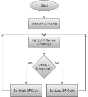
Algorithm
- Initialize GPIO port pin
- Get light sensor values
- Check if the value is less than threshold
- If yes, set GPIO pin high else set low
Flow Chart
Code Snippet
 /*Initialize*/

       GPIO headlight(P1_22);
       headlight.setAsOutput();
       headlight.setLow();
 /*Check Threshold*/

       uint8_t light_percent=LS.getPercentValue();
       if(light_percent<LIGHT_THRESHOLD)
       {
            headlight.setHigh();
       }
       else if(light_percent>LIGHT_THRESHOLD)
       {
            headlight.setLow();
       }
Testing & Technical Challenges
PCB
In designing the PCB, we worked on EAGLE, which was a whole new experience.Below listed are the major challenges faced by us:
- We found that the maximum size of the PCB can be 10x5.5 inch as the software used a freeware, and hence it has its limitations.
- Common Ground: The board as a whole needs to be grounded. This is to avoid unwanted issues; the unused pins are grounded as well as the common ground needs to be taken care off. We were unfamiliar with the ground plane handling. Initially, as there is no direct connection or ground pin for the PCB. After careful observation, we got to know the working of ground plane on the PCB.
- Missing Connections: The circuit once completed needs to be properly checked. We used Auto Routing facility to connect the PCB connectors but found due to space constraint; the tool missed some ports unconnected. So before the final ordering, careful check of connections needs to be done.
- Ordering and soldering need to be done carefully as per the package/device name of the connector used in the design.
- Soldering the micro USB component was tough since the pins were tiny
Text to Speech Module
- Text to speech module is easy to interface with the microcontroller. Just connect the module to UART pins of the microcontroller and it is up and running.
- We wrote a special terminal command for testing our module.
CMD_HANDLER_FUNC(TTSDirHandler);
   cp.addHandler(TTSDirHandler,     "TTS",    "Text to speech direction command Ex: 'TTS right/ TTS left'");
CMD_HANDLER_FUNC(TTSDirHandler)
{
   if(cmdParams.containsIgnoreCase("right"))
   {
       LE.toggle(1);
       SelectText = RightDirection;
   }
   else if(cmdParams.containsIgnoreCase("left"))
   {
       LE.toggle(2);
       SelectText = LeftDirection;
   }
   else
   {
       output.putline("Error in command");
   }
      return true;
}
Distance Sensor
- To test the distance sensor for our application, we created a testing environment. We marked the different distance of 10m at every meter. Keeping the object at one location, we moved the sensor at different distances to simulate the moving bicycle.
- During the testing phase, we found that the sensors must have sufficient timing in between two triggers. If it is not given then, the sensor will give wrong readings, and its behavior will be unpredictable.
- In our application, most of the time sensor will be in open space without any obstacles. We needed to test our sensors in open air. During open air testing, our first sensor was not giving the readings as mentioned in the datasheet. Readings were always below 2 meter which is very less than our expectation of 6m. Later we replaced the old sensor with the same type of new sensor.
Turn Angle Detection Sensor
- We completed our turn angle testing in two phases. In the first phase, we tested the sensor by moving the handlebar with the stationary bicycle. All readings given by the ADC were within the acceptable range.
- Threshold value for the LED blinking was set up in the second phase of the testing. In the second phase, we mounted the sensor, controller board on the bicycle and we logged the ADC readings on the memory card. With all the arrangement on the bicycle, we rode the bike on the road. By analyzing the logged data, the threshold value for LED indicator blinking was set.
- We faced a lot difficulty in finalizing the turn angle sensor. We tried three different sensors as described in the turn angle detection section. We would like to advise to complete the rigorous market survey before settling any sensor. Use exact literal words of the purpose for which you are using the sensors while searching on the google.
Hardware Difficulties
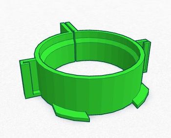
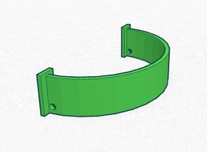
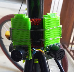
- We have a lot of hardware mounting in this project. While mounting different peripherals on the bike, we had to design custom hardware. We designed our own hardware and got it 3D printed.
- Two types of sensors mounted on the bike are connected to the controller via wires and making this long wire was a time-consuming task. We had to handle this wire very carefully. During the testing one of the wire got damaged and sensors stopped working. We debugged this issue by checking the connectivity of wires and replaced the damaged wire.
Working with LED's
- We tried and bought a variety of LED's to work with. We found that while working with LED's one has to be very careful. The LED's are not reliable to start and can be damaged easily. The input power and data needs to taken care off. Also, the LED's are joint togetherby solder. Any mishandling and the LED's can get damaged.
Conclusion
This project was a success and the overall objectives of the project were met. The various sensors communicate seamlessly with the microcontroller and provide feedback to the cyclist via text-to-speech. The front headlight and back LEDs operate as we planned them to, the front headlight only turns on when it is dark outside and the appropriate back LED turn signals flash when the bicyclist is making turns. This project was exciting to work on since it incorporated so many various sensors and modules that had to interact together with the SJOne board. This project increased our knowledge in both software and hardware domain. We learned valuable lessons and had to overcome some difficulties with choosing the appropriate hardware for the Biker Assist project. Designing the PCB was a rewarding experience and it gave us confidence in our ability to design a PCB for a specific project.
Project Video
Project Source Code
Acknowledgement
We would like to Thank Preetpal Kang,our instructor and motivator for the class. Without his help and ideas,we wouldn't be able to complete the project. He provided the knowledge that we easily replicated in successfully completing the project. We used his API's and coding standards that helped us in building our project and will help us in the near future.
