Difference between revisions of "F16: The-Nine"
Proj user8 (talk | contribs) (→Implementation) |
Proj user8 (talk | contribs) (→Parts List & Cost) |
||
| Line 225: | Line 225: | ||
| 1 | | 1 | ||
| $25.00 | | $25.00 | ||
| + | |- | ||
| + | ! scope="row"| 10 | ||
| + | | MB1010 Ultrasonic Sensors | ||
| + | | Jameco | ||
| + | | 3 | ||
| + | | $74.85 | ||
| + | |- | ||
| + | ! scope="row"| 11 | ||
| + | | Assorted components for PCB | ||
| + | | Mouser | ||
| + | | 1 | ||
| + | | $31.60 | ||
| + | |- | ||
| + | ! scope="row"| 12 | ||
| + | | PCB manufacturing service | ||
| + | | Bay Area Circuits | ||
| + | | 1 | ||
| + | | $32.64 | ||
| + | |- | ||
| + | ! scope="row"| 13 | ||
| + | | GPS sensor | ||
| + | | Adafruit | ||
| + | | 1 | ||
| + | | $50.00 | ||
|- | |- | ||
|}</center> | |}</center> | ||
Revision as of 01:28, 21 December 2016
Contents
- 1 Project Title
- 2 Abstract
- 3 Objectives & Introduction
- 4 Project Schedule Overview
- 5 Team Members & Responsibilities
- 6 Parts List & Cost
- 7 Bluetooth Communications (Communication Bridge)
- 8 Obstacle Detection Systems (Sensor Controller)
- 9 Localization and Positioning (GPS)
- 10 Propulsion Systems and Speed Tracking (Motor Controller)
- 11 Master Control Systems
- 12 Conclusion
- 13 Project Video
- 14 Project Source Code
- 15 References
Project Title
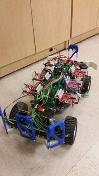
The-Nine: Self Driving Car
Abstract
Nearly every car manufacturer today is in the process of developing fully autonomous vehicles. There are some that are on the brink of winning the development race as their systems are safer than many human drivers. However currently no one has been able to fully implement autonomous navigation requiring nothing but a destination while having the full support and trust of the community to remove the driver from the equation. Autonomous vehicles are incredibly difficult to create as there are a huge number of difficulties of autonomy that must be taken into account. The purpose of this project is to introduce the basic technologies in application of the types of systems that can be used in autonomy. The overall project goal is to make an autonomous RC car that utilizes five SJSU-One-Boards that intercommunicate with each other through CANbus; each controlling a major functionality. The RC car must be able to be given a destination through an interfacing application and it must be able to travel to that location.
Objectives & Introduction
This project aimed towards developing and building a RC car which has the self-driven capability. We communicated over CAN bus. The car is capable to find its current location through the GPS module. The car could get the destination and way points through the google map API which is connected to the android application, and bluetooth and through CAN messages is sent over to the GPS and it could find its path to the destination while avoiding any obstacles that might run into while driving to the destination. To achieve this objective, we used 5 controllers, which each is dedicated to a specific role such as master, sensors, bluetooth, motors and geographical location. These controller can pass messages over the common CAN bus. In addition, the final prototype of has android application which is useful for data monitoring and keep tracking of the car remotely. Through the android application, the user can feed the desired destination and the car is capable of finding its path to the destination. The car follows the direction based on the data that is provided by the sensors, GPS and compass values.
Project Objectives
- Primary
Use CANbus to intercommunicate between the different controllers on the car.
- Master Controller
Take in data from all controllers to make a logical decision on how to control Speed and Steering to get to a location and avoid obstacles.
- Bluetooth Controller
Make a Bluetooth Connection to the user interfacing application to display telemetry information on the application and to receive target locations for the car to travel to. In charge of I/O such as headlights and physical switches.
- Motor and Display Controller
Get commands from the master controller and control the drive motor and steering servo. Collect Drive motor feedback and make sure the drive motor is running at its target speed. Display Useful through some type of LCD Display.
- GPS Controller
Gets waypoints from the bluetooth and find the target heading to the nearest waypoint, and calculate the distance. As the car gets closer to the waypoint, checks if it is in range, if so it will move one to the next waypoint.
- Sensor Controller
Collect ultrasonic sensor and magnetometer data, battery voltage and send back to master controller.
Project Schedule Overview
| Task # | Start Date | End Date | Team Task Description | Bluetooth Communications | Obstacle Detection Systems | Localization and Positioning (GPS) | Propulsion Systems and Speed Tracking | Master Control Systems | Status | Actual End Date |
|---|---|---|---|---|---|---|---|---|---|---|
| 1 | 9/14/2016 | 9/20/2016 | Assigned tasks to one another and strategized approach. Read Previous Reports | Completed | 9/20/2016 | |||||
| 2 | 9/21/2016 | 9/27/2016 | Set up Version Control System and Basic Project Documentation Research Project Components |
Research of web application frameworks for mobile. | Research of sensor systems and sensor types needed. | * Researched and decided upon the GPS module and Compass module. * Ordered GPS module and compass module. |
Work with team leader to devise version control strategy. | Research different RC cars for the project. | Completed | 9/27/2016 |
| 3 | 9/28/2016 | 10/04/2016 | Discuss controllers' responsibilities and communication | Started development of DBC and finalized hardware choices. | Completed | 10/04/2016 | ||||
| 4 | 10/05/2016 | 10/19/2016 | Order Project Components Individual Prototyping and Module Design |
Research Bluetooth device HC-06 for the RC car. | Interface IMU and ultrasonic sensors to board. | * Parse GPS data and format the data to be transmitted * Test code to get compass reading information |
Research what encoders and/or tachometers to use, help the team leader choose an RC car to purchase, and decide what motor driver to use | Implement Decision Tree for obstacle detection/autonomous car control. Decide on Message ID system over the CANBUS/Types of Data being Transmitted | Completed | 10/19/2016 |
| 5 | 10/20/2016 | 10/27/2016 | Status Update: Demoing first round of Prototyping to the group | Develop Bluetooth serial receiver library & web application. | Develop IMU and ultrasonic sensor libraries. | Interface GPS module and compass module to SJOne board. | Make the motors spin and the servo control the steering. Receive can signals and control the motor and steering servo. | * Implement Decision Tree for obstacle detection/autonomous car control. Decide on Message ID system over the CANBUS/Types of Data being Transmitted * Program obstacle detection/autonomous car control algorithms |
Completed | 10/27/2016 |
| 6 | 10/28/2016 | 11/18/2016 | Adding a level of complexity to designs: Interfacing Motor, Sensor, GPS, and Bluetooth Modules with the Master Controller over CAN bus | Integrate web application, SJOne board and DBC messages | Use implemented DBC to transmit sensor data over CAN. | * Calibrating the compass module.Integration of GPS and compass module. Interfacing of GPS and compass module to Android. * Integration with Master through CAN bus. |
* Validate and calibrate the motor controller and steering code. Receive the Tachometer and magnetic polarity strip. * Merge motor_test/tach with master. * Reorganize code for readability. * Finalize and test speed feedback system. |
* Program obstacle detection/autonomous car control algorithms * Test RC car obstacle detection and autonomous control interfaced with Sensor Module over CAN * Interface GPS module with Master Controller * Interface Android/Bluetooth module with Master Controller.Test Waypoint System |
Completed | 11/18/2016 |
| 7 | 11/19/2016 | 11/25/2016 | Integration Testing between Modules, System Validation | Fine-tuning of web application | Debug sensor library and work on integration | Testing and calibrating with other modules. | Test with the rest of the group * Fine tune nominal speed. Add LCD to display debug information. |
* Interface Android/Bluetooth module with Master Controller.Test Waypoint System * Debug any issues with Master controller and other modules |
Completed | 11/28/2016 |
| 8 | 11/26/2016 | 12/02/2016 | Overall System Optimization | Fine-tuning of sensor readings | Testing and calibrating with other modules. | * Replace motor driver with higher amperage driver. * Adjust steering offset to reduce error. |
* Debug any issues with Master controller and other modules * Final debug/testing of RC CAR |
Completed | 12/04/2016 | |
| 9 | 12/03/2016 | 12/09/2016 | Finalization, Preparing for Demonstration | Completed | 12/08/2016 | |||||
Team Members & Responsibilities
Application & Control Interface
- Khalil Estell
Bluetooth Communications
- Khalil Estell
Obstacle Detection Systems
- Charles MacDonald
- John Strube
Localization and Positioning (GPS)
- Sara Sepasian
Propulsion Systems and Speed Tracking
- Derek Tran
- Matthew Boyd
Master Control Systems
- Steven Hwu
- Adam Iglesias
Parts List & Cost
Give a simple list of the cost of your project broken down by components. Do not write long stories here.
| Item # | Part Description | Vendor | QTY | Cost |
|---|---|---|---|---|
| 1 | RC Car | Nor-Cal Hobbies | 1 | $200 |
| 2 | SJSUOne Board | Preet Kang | 5 | $400.00 |
| 3 | HC-06 Bluetooth Module | Amazon | 1 | $8.99 |
| 4 | Magnetic Tachometer | Digikey | 1 | $8.53 |
| 5 | Radial Magnet cube magnets | Digikey | 10 | $8.80(Total) |
| 6 | Pololu 5V Step-Up/Step-Down Voltage Regulator | Polulu | 1 | $14.95 |
| 7 | Pololu 6V Step-Up/Step-Down Voltage Regulator | Polulu | 1 | $14.95 |
| 8 | High Power Motor Driver | Polulu | 1 | $39.95 |
| 9 | 2000mAH 3 Cell Lipo Battery | HobbyKing | 1 | $25.00 |
| 10 | MB1010 Ultrasonic Sensors | Jameco | 3 | $74.85 |
| 11 | Assorted components for PCB | Mouser | 1 | $31.60 |
| 12 | PCB manufacturing service | Bay Area Circuits | 1 | $32.64 |
| 13 | GPS sensor | Adafruit | 1 | $50.00 |
Bluetooth Communications (Communication Bridge)
Schedule
| Task # | Start Date | End Date | Task Description | Status | Actual End Date |
|---|---|---|---|---|---|
| 1 | 9/14/2016 | 9/20/2016 | Assigned tasks to one another and strategize approach. | Completed | 9/20/2016 |
| 2 | 9/21/2016 | 9/27/2016 | Research of web application frameworks for mobile. | Completed | 9/27/16 |
| 3 | 9/28/2016 | 10/04/2016 | Started development of DBC and finalized hardware choices. | Completed | 10/04/2016 |
| 4 | 10/05/2016 | 10/19/2016 | Research Bluetooth device HC-06 for the RC car. | Completed | 10/19/2016 |
| 5 | 10/20/2016 | 10/27/2016 | Develop Bluetooth serial receiver library & web application. | 10/19/2016 | |
| 6 | 10/20/2016 | 11/18/2016 | Integrate web application, SJOne board and DBC messages | 11/12/2016 | |
| 7 | 11/19/2016 | 12/02/2016 | Fine-tuning of web application | CONTINUOUS TASK | |
| 8 | 12/03/2016 | 12/09/2016 | Final integration | Completed | 12/08/2016 |
Design & Implementation
Hardware Design
Discuss your hardware design here. Show detailed schematics, and the interface here.
Hardware Interface
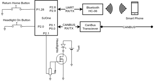
The HC-06 bluetooth Serial device can be interfaced via UART. Simply, connect the Bluetooth RX -> the SJOne TX and connect the Bluetooth TX -> the SJOne RX. Any serial Bluetooth data transmitted to the HC-06 from a master bluetooth device will propagate to the Bluetooth TX pin. Send bytes through UART via the SJOne TX pin in order to transmit to the master bluetooth device.
Two tactile buttons are connected to GPIs on the SJOne board.
One PWM output (P2.1) from the SJOne board is connected to a logic level mosfet to control the brightness of an white light led strip.
Software Design
Show your software design. For example, if you are designing an MP3 Player, show the tasks that you are using, and what they are doing at a high level. Do not show the details of the code. For example, do not show exact code, but you may show psuedocode and fragments of code. Keep in mind that you are showing DESIGN of your software, not the inner workings of it.
Implementation
void period_1000Hz(void)
{
	if(led_btn_is_released)
	{
		manually_increment_headlights();
	}
	if(gps_btn_is_release)
	{
		send_fixed_gps_location();
	}
	automatic_headlights_control();
}
void period_10Hz(void)
{
	handle_can();
	send_master_control_signal();
	if(gps_queue_ready)
	{
		send_gps_queue();
	}
}
void period_100Hz(void)
{
	handle_uart();
}
This section includes implementation, but again, not the details, just the high level. For example, you can list the steps it takes to communicate over a sensor, or the steps needed to write a page of memory onto SPI Flash. You can include sub-sections for each of your component implementation.
Testing & Technical Challenges
Describe the challenges of your project. What advise would you give yourself or someone else if your project can be started from scratch again? Make a smooth transition to testing section and described what it took to test your project.
Include sub-sections that list out a problem and solution, such as:
Issue #1: Keeping up with the DBC File
In the beginning of the
Obstacle Detection Systems (Sensor Controller)
Schedule
| Task # | Start Date | End Date | Task Description | Status | Actual End Date |
|---|---|---|---|---|---|
| 1 | 9/14/2016 | 9/20/2016 | Assigned tasks to one another and strategized approach. | Complete | 9/20/2016 |
| 2 | 9/21/2016 | 9/27/2016 | Research of sensor systems and sensor types needed. | Complete | 9/27/2016 |
| 3 | 9/28/2016 | 10/04/2016 | Started development of DBC and finalized hardware choices. | Complete | 10/04/2016 |
| 4 | 10/05/2016 | 10/19/2016 | Interface IMU and ultrasonic sensors to board. | Complete | 10/19/2016 |
| 5 | 10/20/2016 | 10/27/2016 | Develop IMU and ultrasonic sensor libraries. | Complete | 10/19/16 |
| 6 | 10/20/2016 | 11/18/2016 | Use implemented DBC to transmit sensor data over CAN. | Complete | 10/19/16 |
| 7 | 11/19/2016 | 11/25/2016 | Debug sensor library and work on integration | Complete | 11/25/16 |
| 8 | 11/26/2016 | 12/02/2016 | Fine-tuning of sensor readings | Complete | 12/1/16 |
| 9 | 12/03/2016 | 12/09/2016 | Final integration | Complete | 12/8/16 |
Design & Implementation
The obstacle detection system covers two areas: detecting obstacles and determining vehicle orientation.
Obstacle detection is performed using ultrasonic sensors placed around the perimeter of the vehicle, concentrated at the front (three sensors) and less so in the back (one sensor) as the vehicle is primarily driven in the forward direction.
Vehicle orientation is accomplished using an inertial measurement unit, which is used to determine the speed and bearing of the vehicle.
Hardware Design
Bumpers and Ultrasonic Mounts
The two bumpers, ultrasonic housings, and headlight mounts were designed using Onshape and 3D printed using PLA plastic. Each bumper was designed to house 3 ultrasonic sensors. The initial ultrasonic housings were designed for the Sparkfun HC-SR04 ultrasonic sensor. The housings were printed in black PLA plastic and modified to snugly fit the sensors. The front and rear bumpers were then designed to mount onto the existing bumpers on the RC car, and to fit the ultrasonic mounts using M3 screws. Both the front and rear bumper were printed in glow in the dark PLA plastic. After the bumpers were printed, we switched to the current MaxSonar sensors, so the new ultrasonic housings were designed to fit the existing bumpers. Each sensor is screwed into the housing using 2 small M3 screws, and each housing is screwed onto the bumper using M3 screws. There are 3 sensors in the front of the car, and one in the rear.
During testing it was determined that we need to tilt the sensors upwards at a 10 degree angle to avoid detecting the floor. The right and left sensors were also tilted 15 degrees outside to better detect obstacles on the side.
A mount to house the LED strip mounts onto the front bumper. The mount fits inside existing holes in the front bumper, but can be screwed in for additional stability. The headlight mount was printed in black PLA plastic.
During further testing it was determined that we need to raise the sensors off the ground to avoid small obstacles on the ground, such as gravel and leaves. New ultrasonic sensor housings were designed in such a way so that the height off the ground can be adjusted. The new adjustable ultrasonic housings were printed in blue PLA plastic.
Ultrasonic sensors
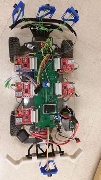
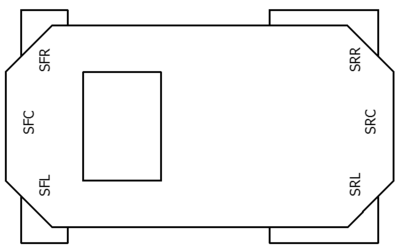
Our original design called for six ultrasonic sensors, with three forward-facing (sensors SFL, SFC, SFR at front-left, front-center, front-right) and three rear-facing (sensors SRL, SRC, SRR at rear-left, rear-center, rear-right). In practice only one center rear-facing sensor was needed, but the design still supports six. The sensors are arranged around the car as follows:
|
The ultrasonic sensors don't have a specific bus (such as SPI or I2C) and instead are triggered asynchronously through GPIO, described later.
Compass
A magnetometer is used to calculate the heading of the car. The magnetometer being used is the HMC5883L. The magnetometer measures the magnetic field of The Earth in units of Tesla as scalars in the X, Y and Z axis. The SJOne board communicates with the magnetometer using I2C at address 0x3C. An accelerometer onboard the SJOne board is used for tilt compensation. The magnetometer is oriented such that X axis faces forward, Z axis faces up, and Y axis faces to the left.
Hardware Interface
I/O expander
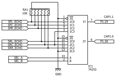
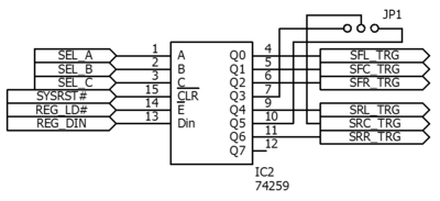
To utilize the limited number of available capture inputs across four to six ultrasonic sensors, an I/O expansion circuit was developed.
It consists of a 74HCT253 dual 4-to-1 multiplexer, and a 74HCT259 8-bit addressable latch. The multiplexer routes the sensor inputs to the two capture pins such that the front and rear sensors can be captured in parallel. To keep our final design compatible with the code developed for our prototype, the rear-center sensor was also mapped to the fourth input of the front-sensor multiplexer inputs such that iterating over four inputs would cover the front three sensors and rear single sensor on the same capture channel.
|
|
| Select | Input on CAP1.0 | Input on CAP0.0 | Addressed register |
|---|---|---|---|
| 0 | SFL_ECHO | SRL_ECHO | SFL_TRG |
| 1 | SFC_ECHO | SRC_ECHO | SFC_TRG |
| 2 | SFR_ECHO | SRR_ECHO | SFR_TRG |
| 3 | SRC_ECHO | Always '0' | SRC_TRG (see JP1) |
| 4 | SFL_ECHO | SRL_ECHO | SRL_TRG |
| 5 | SFC_ECHO | SRC_ECHO | SRC_TRG (see JP1) |
| 6 | SFR_ECHO | SRR_ECHO | SRR_TRG |
| 7 | Always '0' | Always '0' | Not used |
Battery voltage monitor
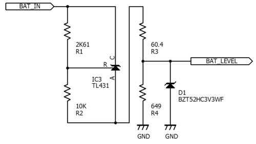
The battery voltage monitor takes the 12.6V battery voltage and scales and offsets it down to a 0 to 3.3V range that the SJOne board can sample on an ADC input. An adjustable zener diode (LM431) along with a voltage divider to set the reference voltage is used to drop 9V from the battery output as the system isn't intended to function below 9V. This leaves a 3.6V range of "useful" voltage to monitor which is further scaled down by another voltage divider to 3.3V. A zener diode is used to clamp the output to 3.3V to protect the SJOne board, as the ADC inputs cannot tolerate an over-voltage condition.
Compass
The SJOne board communicates with the HMC5883L using I2C bus 2, using slave address 0x3C. The magnetometer is oriented such that the X axis faces forward, the Y axis faces left, and the Z axis faces up. SDA and SCL pins are connected to the SDA2 and SCL2 pins on the SJOne, GND is connected to GND, and VCC is connected to 3.3V.
Software Design
Ultrasonic sensors
Overview
A sensor polling loop starts every second (1 Hz). Within this loop all four sensors are read, the distances are calculated and output on the CAN bus, and the elapsed time is determined. If there is enough time remaining to do a worst-case read of all four sensors (approximately 200ms), the sensors are read again.
The sensors are cycled through as soon as one finishes. This makes the refresh rate dynamic, ranging from a worst-case update rate of 5 Hz (50ms x 4 sensors = 200ms) up to 20 Hz. Even if polling of all four sensors finishes before a 50ms interval has expired, polling can't continue as each sensor must be idle for 50ms before being triggered again. On average this yields a sensor update rate of 16 Hz.
Polling internals
The capture function of timer #1 is triggered on the rising edge and the falling edge, and an interrupt is generated on each capture event. The ISR saves the captured value on each edge and computes the difference between them to determine the length of the sensor's pulse. A state machine is used to keep track of events per sensor (ranging request, positive edge received, negative edge received).
Battery voltage monitor
The battery voltage is read after the sensors are polled using the ADC. This data is sent to the rest of the system over the CAN bus.
Compass
The compass headings are calculated 10 times a second using the period_10Hz task in period callbacks. An exponential moving average is used to smooth out the raw magnetometer and accelerometer data. A weight of .5 was used to smooth out the magnetometer, and a weight of .1 was used to smooth out the accelerometer. The magnetic and acceleration vectors as measured from the magnetometer and accelerometer are then normalized such that the length of the vectors is 1.0. Because a gyroscope is not being used to assist in tilt compensation, a very low weight must be used to compensate for the car accelerating forward and backward. Tilt compensation is used to ensure an accurate compass reading when the car is titled. The tilt compensation algorithm uses the roll and pitch as calculated from the accelerometer and the X Y and Z components of the normalized magnetometer vector. The calculated heading is then converted from radians to degrees. The magnetic declination offset angle is then added to the heading to account for the differences between magnetic and true north. The heading will then be sent to Master, BlueTooth, and Debug over Can bus.
Implementation
This section includes implementation, but again, not the details, just the high level. For example, you can list the steps it takes to communicate over a sensor, or the steps needed to write a page of memory onto SPI Flash. You can include sub-sections for each of your component implementation.
Compass
To communicate with the magnetometer sensor, a singleton class named IMU_Sensor was created. The class stores sensor data in a local struct, and handles initialization of the sensor, and reading raw magnetometer sensor data.
Measuring the raw sensor data
The IMU_Sensor class communicates with the magnetometer using I2C at address 0x3C. The period_init function in periodic callbacks calls the init function, which sets the two configuration registers and the mode register using the I2C2 class. Ten times per second the periodic scheduler calls the getXYZ() function. Six registers are read, starting at 0x03, which store the high and low bites for the X, Z, and Y axis of the magnetometer. If the readRegisters function returns false, the getXYZ function returns false. A zero byte is then written to register 0x03 to reset the internal pointer and prepare for the next measurement. The table below lists the relevant registers.
| Address Location | Name |
|---|---|
| 0x00 | Configuration Register A |
| 0x01 | Configuration Register B |
| 0x02 | Mode Register |
| 0x03 | Data Output X MSB Register |
| 0x04 | Data Output X LSB Register |
| 0x05 | Data Output Z MSB Register |
| 0x06 | Data Output Z LSB Register |
| 0x07 | Data Output Y MSB Register |
| 0x08 | Data Output Y LSB Register |
Calculating Heading
The period_10Hz reads the raw values from both the magnetometer using the IMU_Sensors class, and from the accelerometer using a built in class. The raw data is then filtered using an exponential moving average, with a weight of 0.5 for the magnetometer and 0.1 for the accelerometer. The magnetometer and accelerometer vectors are then normalized. Roll and pitch are then calculated using the normalized accelerometer vector. The roll is calculated by taking the arcsin of the negative X component, and the pitch is calculated by taking the arcsin of the Y component. The following formula is used to calculate the tilt compensated vector.
hy = normHy * cos(roll) + normHx * sin(roll) * sin(pitch) - normHz * cos(pitch) * sin(roll)
hx = normHx * cos(pitch) + normHz * sin(pitch)
The heading in radians is then calculated by taking the arctan of the Y and X components of the tilt compensated vector. The declination angle (13 degrees for San Jose) is then added to the current heading. The heading in radians is then converted into degrees. The heading in degrees is then sent over Can Bus to be received by Master, Bluetooth, and Debug.
Testing & Technical Challenges
Compass
Initial Testing
Initial testing was done by connecting the magnetometer to the SJOne board and printing out the calculated heading over serial. By rotating the magnetometer, the current heading can be verified by using a real compass.
Testing on the car
The magnetometer was then installed on the car. Using the bluetooth app, the current heading can be displayed. The car was then successfully tested indoors. During the outdoor test runs, it was discovered that the compass loses accuracy when the car is on a slope. This was due to the lack of tilt compensation, because only the X and Y axis of the magnetometer are used to calculate heading.
A tilt compensation algorithm was then implemented using the accelerometer onboard the SJOne board. Again, the magnetometer was tested first off the car by using the serial console. The compass was tested by rotating and tilting and observing the calculated heading. After the tilt compensation was verified outside the car, it was again installed in the car. The car was tested by driving around campus. The tilt compensated compass worked as expected, although a small difference was noticed between calculated heading and actual heading. The observed difference is due to magnetic declination, the difference between magnetic and true north. The magnetic declination for San Jose, CA was determined to be 13 degrees. An offset of 13 degrees was added to the calculated heading.
After further testing with the car with the PCB installed, it was determined that the tilt compensation algorithm was not working correctly. The tilt compensation was disabled, and the car was tested without it. It was determined that the compass without tilt compensation works well enough, so the tilt compensation was disabled for the final build.
Ultrasonic sensors
Calibration
The MB1010 sensor calibrates itself when power is applied. To prevent improper calibration, it's important to have no objects blocking the sensors during power-up. When testing we elevated the front of the car to point the sensors upwards and out into open air where there were no obstacles. A similar procedure was used when testing the rear sensors as well. During outdoors testing we had to be mindful about turning on the car while not blocking sensors either.
Recalibration
According to the manufacturer the MB1010 requires recalibration when the operating voltage, temperature, or location changes. While these criteria are mostly constant during testing, they can fluctuate somewhat. Specifically this need manifested itself as a condition where after normal operation for some duration of time, a sensor begins to report the minimum distance (~14cm) regardless of what is in front of the sensor. This behavior persists until power is cycled, at which point recalibration occurs and normal operation resumes.
Our solution was to add a TPS2034 two-channel power switch to manually cycle the sensor power rails under software control. One channel was for the forward-facing sensors, another for the rear-facing sensors. To determine when recalibration is needed, the past history of sensor readings are scanned to see if any are stuck and are consistently reporting the same minimum value. If any are stuck the power is cycled using the TPS2034. This allowed the sensors to be recalibrated automatically during operation. In addition, during calibration a status signal is sent to
The TPS2034 is a two-rail switch and was used to control the front (3) and rear (1) sensors. In retrospect a better use would be the TPS2054 which has four independent outputs, such that individual sensors could be recalibrated without disturbing the other ones.
RS-232 testing
The MaxBotix LV-MaxSonar-EZ1 (P/N# MB1010) has several interfaces used to indicate the distance to an obstacle that it has sensed. One of the simplest is a RS-232 output which is enabled by grounding the BW pin or leaving it unconnected (floating). The output is logic-level compatible with RS-232 (where a logic '1' is 0V and a logic '0' is Vcc) but not voltage-level compatible. MaxBotix designed the RS-232 output like this to allow direct connection to a RS-232 compliant serial port, but it means the logic levels are inverted with respect to the LPC1758 which has no on-chip provisions for inverting the logic level. Therefore an inverter (such as the 74LVC1G04) is required between the TX output of the MB1010 and the LPC1758's UART RX input for proper operation.
Printed Circuit Board
A printed circuit board was designed in EAGLE to integrate all of the wiring and components that were previously implemented on protoboard and using point-to-point wiring. The board was designed to have several features fur redundancy such as sockets for external CAN transceivers in case the built-in ones failed and breaking out the SJOne board pins to extra headers to add additional peripherals or test signals. Each SJOne board interfaced to the car using a ribbon cable with crimped IDC headers. The silk screen layer was utilized to label all connectors and polarities for power connectors as well.
Localization and Positioning (GPS)
Schedule
| Task # | Start Date | End Date | Task Description | Status | Actual End Date |
|---|---|---|---|---|---|
| 1 | 09/16/2016 | 09/22/2016 | Researched and decided upon the GPS module and Compass module. | Completed | 09/22/2016 |
| 2 | 9/23/2016 | 9/30/2016 | Ordered GPS module and compass module. | Completed | 09/30/2016 |
| 3 | 10/01/2016 | 10/14/2016 | Parse GPS data and format the data to be transmitted Test code to get compass reading information |
Completed | 10/04/2016 |
| 3 | 10/15/2016 | 10/25/2016 | Interface GPS module and compass module to SJOne board. | Completed | 10/19/2016 |
| 4 | 10/26/2016 | 10/30/2016 | Calibrating the compass module.Integration of GPS and compass module. Interfacing of GPS and compass module to Android. | Completed | 10/19/2016 |
| 5 | 11/01/2016 | 11/13/2016 | Integration with Master through CAN bus. | Completed | 10/19/2016 |
| 6 | 11/15/2016 | 12/10/2016 | Testing and calibrating with other modules. | Completed | 12/08/2016 |
Design & Implementation
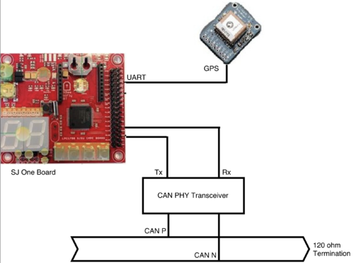
The GEO Controller is responsible for calculating/ providing the location which the car is currently at and target direction to the master controller and bluetooth. The GEO controller will receives the way-points from the Bluetooth Controller and calculates the target heading to the closest waypoint an. The Master Controller is still responsible for controlling the logic of forward, backward, left, and right to reach the final destination. We were able to receive data from GPS module at 10Hz and communicate at 38400bps through UART. We sent specific data packets to receive the GPS module to be able to read the $GPGGA( Global Positioning System Fix Data) string over the UART from the module.
Hardware Design
GPS module used in our project is Adafruit Ultimate GPS Breakout - 66 channel w/10 Hz updates - Version 3 and GPS external active antenna. We were able to configure this module at 10Hz and communicate at 38400bps through UART. The GPS module had 10Hz update rate with low current draw which helped power usage very low. The GPS module GPS can also be configured to operate and communicate at various speed though the provided Graphical User Interface. This module has got an on-board flash to store these configuration which us a built in data-logging capability.
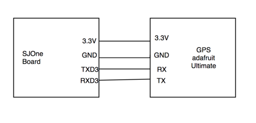
Hardware Interface
| Device | Port Source | Port Destination | Device |
|---|---|---|---|
| SJ One | 3v3 | Vin | Adafruit GPS |
| SJ One | GND | GND | Adafruit GPS |
| SJ One | TXD3 | RX | Adafruit GPS |
| SJ One | RXD3 | TX | Adafruit GPS |
Software Design
The GEO Controller is responsible for retrieving the data from GPS and parsing this information and calculate the needed values. After parsing the NMEA string, the current location is known and we can calculate the target value to the closest way point which has been received from bluetooth controller must be calculated to help the car move in the correct direction. When the correct heading is calculated, which target has been calculated we sent out the data over CAN communication to master and bluetooth controllers.
GPS Data Format
The Data that was retrieved from GPS is in NMEA 0183 format. NMEA is a combined electrical and data specification for communication between marine electronic devices such GPS receivers and many other types of instruments. The sting we received is in this format: $GPGGA,hhmmss.ss,llll.ll,a,yyyyy.yy,a,x,xx,x.x,x.x,M,x.x,M,x.x,xxxx*hh. Which each section describe an specific characteristic of the data. The following table shows format description of each substring within the received string from GPS module.
| Name | Example Data | Description |
|---|---|---|
| Sentence Identifier | $GPGGA | Global Positioning System Fix Data |
| Time | 170834 | 17:08:34 Z |
| Latitude | 4124.8963, N | 41d 24.8963' N or 41d 24' 54" N |
| Longitude | 08151.6838, W | 81d 51.6838' W or 81d 51' 41" W |
| Fix Quality | 1 | Data is from a GPS fix |
| # of Satellites | 05 | 5 Satellites are in view |
| Horizontal Dilution of Precision | 1.5 | Relative accuracy of horizontal position |
| Altitude | 170834 | 280.2 meters above mean sea level |
| Height of geoid above WGS84 ellipsoid | -34.0, M | -34.0 meters |
| Time since last DGPS update | blank | No last update |
| GGPS reference station id | blank | No station id |
| Checksum | *75 | Used by program to check for transmission errors |
System Flow Table
| Task Name | Purpose |
|---|---|
| Periodic 10Hz Callback |
|
| Periodic 100Hz Callback |
|
Algorithm
Finding the TARGET between two coordinates.
/*::::::::::::::::::::::::::::::::::::::::::::::::::::::::::::::::::::*/
/*::  This function calculates heading based on the 2 coordinates    :*/
/*::::::::::::::::::::::::::::::::::::::::::::::::::::::::::::::::::::*/
double gps_heading(double lat1, double lon1, double lat2, double lon2){

    double head = 0 , lon_difference = 0;
    lat1 = (lat1 * PI)/ PI_DEGREES;
    lon1 = (lon1 * PI)/ PI_DEGREES;
    lat2 = (lat2 * PI)/ PI_DEGREES;
    lon2 = (lon2 * PI)/ PI_DEGREES;
    lon_difference = lon2 - lon1;

    head = atan2((sin(lon_difference)*cos(lat2)), ((cos(lat1)*sin(lat2))-(sin(lat1)*cos(lat2)*cos(lon_difference)))) ;
    head = (head * PI_DEGREES)/ PI;

    if( head <= 0 )
        head += 360;

    return head;
}
Finding the distance between two coordinates.
/*::::::::::::::::::::::::::::::::::::::::::::::::::::::::::::::::::::::::::::::*/
/*::  This function calculates distance between the two coordinates in meters  :*/
/*::::::::::::::::::::::::::::::::::::::::::::::::::::::::::::::::::::::::::::::*/
double distance(double lat1, double lon1, double lat2, double lon2) {
    double theta, dist;
    theta = lon1 - lon2;
    dist = sin(deg2rad(lat1)) * sin(deg2rad(lat2)) + cos(deg2rad(lat1)) * cos(deg2rad(lat2)) * cos(deg2rad(theta));
    dist = acos(dist);
    dist = rad2deg(dist);
    dist = dist * 60 * 1.1515;
    dist = dist * 1609.344;
    return (dist);
}
Testing & Technical Challenges
The GPS device should start transmitting NMEA sentences over the TX pin as soon as it is powered up, but the problem was that I wasn't able to retrieve data fast enough by sending out packages to the GPS module such as "$PMTK314,0,1,0,1,0,0,0,0,0,0,0,0,0,0,0,0,0,0,0*28" to turn ON the GGA first, which helped us exploring our other options to make commands that are capable changing the update rate and also put the GPS module in the stand by command. Adding an external antenna was helpful to get the fixed data faster and definitely having an external antenna helped making the processes much faster.
The most important part was that we tried writing a unit test for the GPS module and it took us awhile to actually write the test but the very nice part was that now the code and also the integration is much simpler and cleaner. Integrating with bluetooth and receiving data and also with the whole system in general became really easy after writing the unit test code which was able to go through the state machine and check the states and properly change and flow through the state machine.
Propulsion Systems and Speed Tracking (Motor Controller)
Schedule
| Task # | Start Date | End Date | Task Description | Status | Actual End Date |
|---|---|---|---|---|---|
| 1 | 9/14/2016 | 9/20/2016 | Assigned tasks to one another and strategized approach. | Completed | 9/20/2016 |
| 1 | 9/21/2016 | 9/27/2016 | Work with team leader to devise version control strategy. | Completed | 9/27/2016 |
| 2 | 9/28/2016 | 10/04/2016 | Started development of DBC and finalized hardware choices. | Completed | 10/04/2016 |
| 3 | 10/05/2016 | 10/19/2016 | Research what encoders and/or tachometers to use, help the team leader choose an RC car to purchase, and decide what motor driver to use | Completed | 10/22/2016 |
| 4 | 10/23/2016 | 10/27/2016 | Make the motors spin and the servo control the steering. Receive can signals and control the motor and steering servo. | Completed | 10/25/2016 |
| 5 | 10/26/2016 | 11/04/2016 | Validate and calibrate the motor controller and steering code. Receive the Tachometer and magnetic polarity strip. | Completed | 11/05/16 |
| 5 | 11/06/2016 | 11/11/2016 | * Merge motor_test/tach with master. * Reorganize code for readability. * Finalize and test speed feedback system. |
Completed | 11/11/2016 |
| 5 | 11/12/2016 | 11/18/2016 | validate the wheel speed control system and calibrate. | Completed | 11/18/2016 |
| 6 | 11/19/2016 | 11/25/2016 | Test with the rest of the group * Fine tune nominal speed. Add LCD to display debug information. |
Completed | 11/28/2016 |
| 7 | 11/29/2016 | 12/02/2016 | * Replace motor driver with higher amperage driver. * Adjust steering offset to reduce error. |
Completed | 12/04/2016 |
| 8 | 12/06/2016 | 12/09/2016 | Test with the rest of the group, and fix any minor issues that come up. * Finalize code and merge into master. |
In progress |
Design & Implementation
Hardware Design
The motor controller board takes charge of two main systems: motoring and steering.
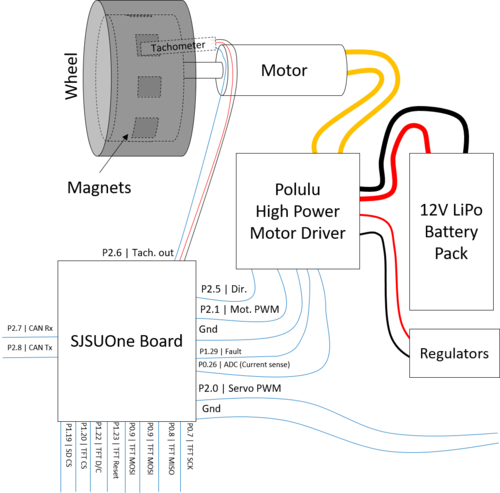
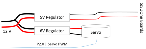
To accomplish motoring, a high power motor driver from Polulu is used to drive the RC car's motor. It takes a simple digital signal for direction and a PWM signal for speed. To help control speed accurately, a tachometer and a set of magnets in a wheel are used to feed back rotations per second (rps). For debugging, a TFT display was connected to the SJSUOne board and displayed tachometer readings versus commanded readings. The figure on the right shows how the SJSUOne board is connected to the display and the motor driver. In addition, the block diagram also shows power connections from the battery.
Steering controlled as simply as the motor. A single wire is needed to feed a PWM signal to the servo. The figure below the motor connections image shows how the servo is connected.
Hardware Interface
Motor
The interface to the motor consists of two sections: feedback and output. The feedback section involves connecting the SJSUOne board to the FAULT and Current sense pins. This allows the board to stop or slow down the motor if problems or overcurrent situations appear. Then the output section consists of a simple digital signal and a PWM signal. The simple digital output controls the direction of the motor: HIGH motors the car forward and LOW motors the car in reverse. To manipulate speed, the duty cycle of the PWM signal is changed according to a PI control algorithm in the SJSUOne board. In order to avoid overcurrent problems, the PWM signal is kept at a high frequency such as 20 kHz.
Tachometer
The tachometer provides information about wheel rotation speed by pulling the its output line low every time the tachometer passes over the south pole of a magnet.
Servo
Controlling the servo requires just one PWM signal. Instead of the duty cycle, the on-time of the signal determines how far the servo turns the car to the left or right. For the servo on this car, the range is 1.300 to 1.900 ms, where 1.5 ms means straight. With this time range, the best frequency for this signal would be 50 Hz. However, since the SJSUOne board provides only one PWM module, a software PWM module was implemented to produce the signal.
TFT Display
A board from Adafruit, the TFT display used for this project communicates with the SPI protocol. However, the board also provides a reset pin and an SD card, so there are a couple of extra pins to choose which device to connect to. The SD card port may be used to log debugging information. For drawing the actual characters, a library from Adafruit was imported.
Software Design
Created Libraries
- Servo Driver (Uses a hardware timer attached to an interrupt to drives a servo at 50 HZ with 100 microseconds of resolution)
- Motor Controller (Runs the control loops that drive the main motor and steering)
- LCD Display Driver(Controls the LCD display. Most functions were imported from the Adafruit library for the device)
- Tachometer Driver (Sets-up/monitors an external interrupt and keeps track of the tachometer ticks)
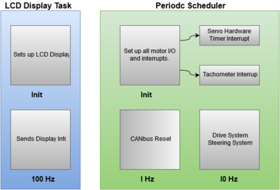
All code on this SJSU-Oneboard software was separated into two running tasks, the Periodic Scheduler and the LCD Display task. The LCD Display was put into its own task due to the need for specific timing requirements that are randomized and large. Typically a custom delay system should be created and put into the periodic scheduler but the LDC display is a low priority objective and a separate task handles its requirements adequately. The periodic scheduler runs every other task on the system. The two subsystems of the periodic scheduler that run on different timing requirements are both the interrupts for the tachometer and the servo hardware timer. Both of these Interrupts are set as lower priority than the periodic scheduler interrupts and RTOS interrupts. This does causes a gap in the hardware timer's control signal for the servo, however the gap is not often enough to cause the servo issues. Furthermore the gap is outside the range of input to the servo so whenever the gap happens, the servo completely ignores it.
Implementation
Motor Control System
Using the 10 Hz periodic scheduler task with a counter, the Motor Control system runs every half a second. This amount of time was selected from the low resolution of eight tachometer ticks per rotation of the car's wheel. In general, the greater the resolution of your feedback in a closed loop system, the faster your control loop can run. Within the Control loop, a system similar to a PI(Proportion, Integral) system was used. When a command from the master controller is sent, that value will get multiplied by a constant and added with an offset. The offset is simply an incremented or decremented value that gets changed according to how far the motors actual speed is from its targeted speed. The Final value is then fed to the motors as a percentage to the PWM I/O that controls the motor's speed.
Servo Hardware Timer
The SJSU-One-Board's PWM controller can only be set to one frequency and with the Motor controller needing to be run at ultra-sonic frequencies, another method to control the servo was needed. To control a servo, a PWM signal running at 50 Hz is needed. Furthermore the positive portion of the PWM wave has to be timed to a specific microsecond value between 1000 microseconds and 2000 microseconds. The method to satisfy these requirements was to implement a hardware timer that triggers an interrupt every 100 microseconds. Inside of this interrupt, is a counter. At a count of zero, a GPIO is set to HIGH and then at a controlled count between 10 to 20, the value is set to LOW. Once the count hits 202, the count is reset.
Testing & Technical Challenges
Motor Driver control
Several times during testing, the SJSUOne board was powered up or reprogrammed while still connected to the motor driver, causing the motor to rev at full speed and destroy the motor driver. The first solution to avoid full speed upon board power up was to add a tri-state buffer between the output of the SJSUOne board and the motor driver. Later on, the team discovered that a single pull-down resistor on the line was sufficient to solve the issue. This taught the team that for future projects involving powered mechanical systems to always make sure the control line by default will keep the systems off, whether by pull-down resistors or tri-state buffers.
PWM accuracy
While testing servo control, the frequency of the generated PWM signal proved to be inaccurate. The generated signal would have a frequency 10 times greater than what is set in the program, leading to inaccurate on-times. The team soon found out that the problem was because of where the PWM object in the program was constructed. Initially, the PWM objects were created in the global scope, meaning the constructor would write to the registers before the main() function was entered. While this problem is not fully understood, it was solved by constructing the objects in init() functions, which were called after the main() function was entered. This shows that, for future drivers written for microcontrollers, driver behaviour would be much more well defined if all register manipulation happened in an init() member function rather than in a constructor. This way, client users do not have to worry about accidentally constructing driver objects in the global scope.
Master Control Systems
Schedule
| Task # | Start Date | End Date | Task Description | Status | Actual End Date |
|---|---|---|---|---|---|
| 1 | 9/14/2016 | 9/20/2016 | Assigned tasks to one another and strategized approach. | Complete | 9/20/2016 |
| 2 | 9/21/2016 | 9/27/2016 | Research different RC cars for the project. | Complete | 10/15/2016 |
| 3 | 10/16/2016 | 10/23/2016 | Implement Decision Tree for obstacle detection/autonomous car control. Decide on Message ID system over the CANBUS/Types of Data being Transmitted | Complete | 10/23/2016 |
| 3 | 10/24/2016 | 10/29/2016 | Program obstacle detection/autonomous car control algorithms | Complete | 10/29/2016 |
| 4 | 10/30/2016 | 11/06/2016 | Test RC car obstacle detection and autonomous control interfaced with Sensor Module over CAN | Complete | 11/06/2016 |
| 5 | 11/07/2016 | 11/13/2016 | Interface GPS module with Master Controller | Complete | 11/13/2016 |
| 6 | 11/14/2016 | 11/20/2016 | Interface Android/Bluetooth module with Master Controller.Test Waypoint System | Complete | 11/20/2016 |
| 7 | 11/21/2016 | 11/27/2016 | Debug any issues with Master controller and other modules | Complete | 11/27/2016 |
| 8 | 11/28/2016 | 12/12/2016 | Final debug/testing of RC CAR | Complete | 12/12/2016 |
Hardware Design
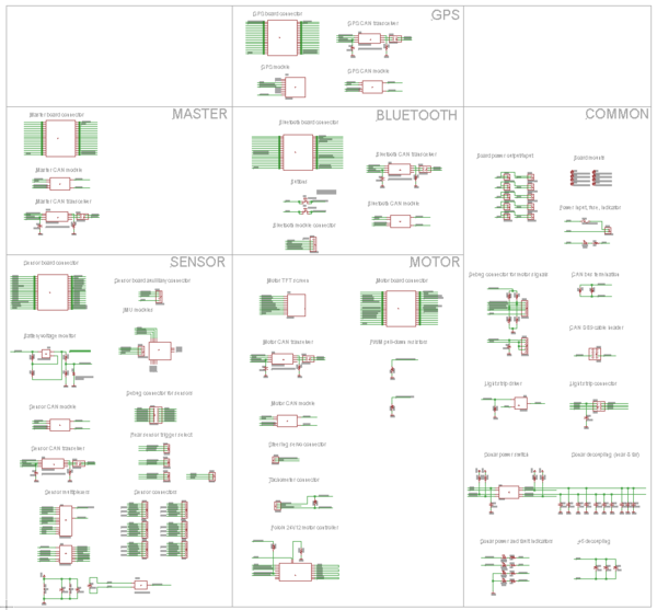
For Master Controller since we did not have to interface with any external peripherals the hardware was very simple and initially only consisted of a SJOne board along with a Waveshare SN65HVD230 CAN transceiver to communicate over the CAN bus. The CAN transceiver was already equipped with internal 120 ohm resistors but when the PCB board was created these transceivers were no longer needed. The RD1 (pin 0.0) and TD1 (pin 0.1) on the SJOne board are connected to the CAN Rx and CAN Tx pins on the CAN transceiver thus using can1 for our SJOne board.
Software Design
Modes of Operation
There are two basic modes of operation for the Master controller. One is the steering control and the other is obstacle avoidance mode. None of these modes are operational until a Master Enable message is received by the master. The steering control mode relies on target and heading messages from the GPS and Sensors nodes to successfully navigate the car to its destination. It is the default mode of operation for the Master Controller. The other mode of operation mentioned is obstacle avoidance mode. The obstacle avoidance mode is only triggered when the front sensors distance values are within a predefined threshold thus telling the car to get out of the way.
Obstacle Detection Algorithm
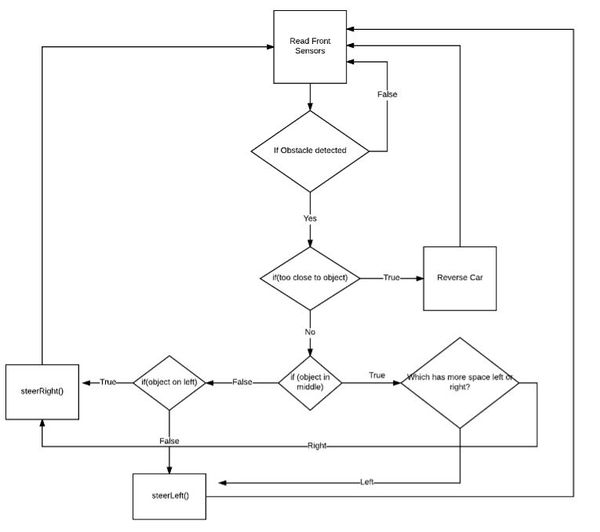
Obstacle avoidance is entirely dependent on the front sensor values and rendered inactive if nothing is being detected. The algorithm is shown below.
Obstacle Avoidance mode is triggered when a front sensor value is within a predefined set of distance thresholds. The speed of the car is also reduced when in this mode to provide enough time to get out of the way. The degree of steering is proportional to how close an object is to the RC car, the closer an object is the harder the steering of left or right. If an obstacle is deemed too close to our RC car, giving us the idea that there's no way to get out of the obstacle's way, the RC car goes in reverse and will continue to do so until the there's enough space in front of it.
Implementation
We had the two modes operating at the 100Hz() task , and we decided to send motor commands at that same frequency. The 100Hz() task also managed the receiving of signals from the GPS and Sensor nodes. Transmitting debug signals caused the issue of overloading the CAN bus at 100Hz so it was designated to the 1Hz() task as these signals were less of a priority.
Software Libraries To avoid an unnecessarily long 100Hz() task that would include our steering and obstacle avoidance code, we included header files for our code, Obstacle_Detect.hpp and vehicle_controls.hpp were included for obstacle avoidance mode and steering control respectfully.
Testing & Technical Challenges
Testing Code Functionality
Since the Master Controller is all but software driven and relies heavily on communication between other CAN nodes , testing the functionality of your code can be a bit tricky especially when outright testing the RC car isn't viable. To fix this we had to familiarize ourselves with the BUSMASTER software as it can easily replicate other nodes. This made debugging much easier and decreased the burden of having to rely on other parts of our RC car that were not ready. Another method we used to unit test our code is the C library <assert.h>. This allowed us to more rigorously test each function of our code by passing in specific parameters that corresponded to specific scenarios into our obstacle detection algorithm and then see if it returned the correct value.
Obstacle Detection Sensor Thresholds and Speed Control
Another issue we faced was on figuring out when Master should trigger obstacle avoidance mode. Alot of trial and error was gone through to properly assess a good speed for the RC car. With the car going faster we noticed that greater obstacle detection distance thresholds needed to be used thus improving the response time of the vehicle and avoiding collisions. We did not want our car to go too fast and destroy itself so we decided on a speed that was a slow and steady pace but not too slow. This provided the car with plenty of time to steer itself out of the way and allowed for smaller distance thresholds for obstacle avoidance to be triggered.
Steering Control for Obstacle Avoidance
There was also the issue of steering to slowly in case of an object is in the way, which often led to it crashing. We tried to incrementally increase the speed of steering by different factors but realized that this was not reliable and often led to crashes. To fix this we decided to adjust the steering so that the rate of steering would increase proportionately to how close it was to an object, this gave us a factor between 0 and +-100.
Conclusion
Conclude your project here. You can recap your testing and problems. You should address the "so what" part here to indicate what you ultimately learnt from this project. How has this project increased your knowledge?
Project Video
Upload a video of your project and post the link here.
Project Source Code
GitLab
References
Acknowledgement
Any acknowledgement that you may wish to provide can be included here.
References Used
List any references used in project.
Appendix
You can list the references you used.
