Difference between revisions of "S16: Sound Buddy"
Proj user12 (talk | contribs) |
Proj user12 (talk | contribs) |
||
| Line 309: | Line 309: | ||
'''Proto-Type''' | '''Proto-Type''' | ||
| − | [[File: | + | [[File:Example.jpg]] |
Describe the challenges of your project. What advise would you give yourself or someone else if your project can be started from scratch again? | Describe the challenges of your project. What advise would you give yourself or someone else if your project can be started from scratch again? | ||
Revision as of 13:40, 9 April 2016
Contents
Grading Criteria
- How well is Software & Hardware Design described?
- How well can this report be used to reproduce this project?
- Code Quality
- Overall Report Quality:
- Software Block Diagrams
- Hardware Block Diagrams
- Schematic Quality
- Quality of technical challenges and solutions adopted.
Project Title
Sound Buddy
Abstract
This section should be a couple lines to describe what your project does.
Sound Buddy is a portable, wireless speaker system designed to play MP3 encoded sound. Load MP3 audio onto an SD card and plug it into the controller box. A Nordic wireless transmitter will wirelessly transmit the file to two receivers. Each receiver will send the file over SPI communication to an MP3 decode board. The MP3 decode boards will decode and convert the file to analog and send it to a speaker.
Objectives & Introduction
Show list of your objectives. This section includes the high level details of your project. You can write about the various sensors or peripherals you used to get your project completed.
Sound Buddy can be broken down into four main efforts: reading the MP3 file, formatting and sending the MP3 over Nordic wireless, receiving the MP3, decoding the MP3 to audio.
Reading the MP3 File The MP3 file is read from the SD card on the SJSU ONE board.
Converting and Sending MP3 over Nordic Wireless The MP3 file is formatted for Nordic wireless transmission. Then sent to two SJSU ONE boards.
Receiving MP3 Files The receiver boards receive the files and prepare them for transmission over an I2C bus to the MP3 decode board.
Decoding MP3 to Audio The decode boards receive the files over the SPI communication link, then reformat the file to standard MP3 and decode it to analog.
Team Members & Responsibilities
- Brigitte De Leon
- Nordic Wireless
- Catherine Gamboa
- PCB Design/Delivery
- Hudo Assenco
- Integration Master
- Yang Thao
- MP3 Decoder
Schedule
Show a simple table or figures that show your scheduled as planned before you started working on the project. Then in another table column, write down the actual schedule so that readers can see the planned vs. actual goals. The point of the schedule is for readers to assess how to pace themselves if they are doing a similar project.
| Week# | Date | Task | Actual |
|---|---|---|---|
| 1 | 03.14 | |
|
| 2 | 03.21 | |
|
| 3 | 03.28 | |
|
| 4 | 04.04 | |
|
| 5 | 04.11 | |
|
| 6 | 04.18 | |
|
| 7 | 04.25 | |
|
| 8 | 05.02 | |
|
| 9 | 05.09 | |
|
| 10 | 05.16 | |
|
Parts List & Cost
| Item# | Part Desciption | Qty | Cost per Item | Cost |
|---|---|---|---|---|
| 1 | STA013 MP3 Decoder Chip | 2 | $11.67 | $23.34 |
| 2 | CS4334 DAC | 2 | $2.97 | $5.94 |
| 3 | Audio Jack 3.5mm | 3 | $1.50 | $4.50 |
| 4 | Crystal 14.7456MHz | 5 | $0.95 | $4.75 |
| 5 | Printed Circuit Boards | 2 | $-.-- | $-.-- |
| 6 | SparkFun SOIC to Dip Adapter 8-pin | 1 | $2.95 | $2.95 |
| 7 | SparkFun SOIC to Dip Adapter 28-pin | 1 | $7.90 | $7.90 |
| 8 | Breakaway headers | 2 | $1.50 | $3.00 |
| 9 | Screw Terminals 3.5mm Pitch(2-Pin) | 3 | $0.95 | $2.85 |
| 10 | Antennas | 2 | $-- | $-- |
| 11 | Resistors | # | $--- | $--- |
| 12 | Capacitors | # | $---- | $---- |
| 13 | Inductors | 2 | $---- | $---- |
| 14 | Voltage Regulators | 2 | $---- | $---- |
| 15 | SJOne Board | 3 | $80.00 | $240.00 |
| Total Cost | $-.-- | $-.-- |
Design & Implementation
The design section can go over your hardware and software design. Organize this section using sub-sections that go over your design and implementation.
The Top Level of Sound Buddy
File:Sound Buddy Top Level.jpg
The Master Board
The Receiver Board
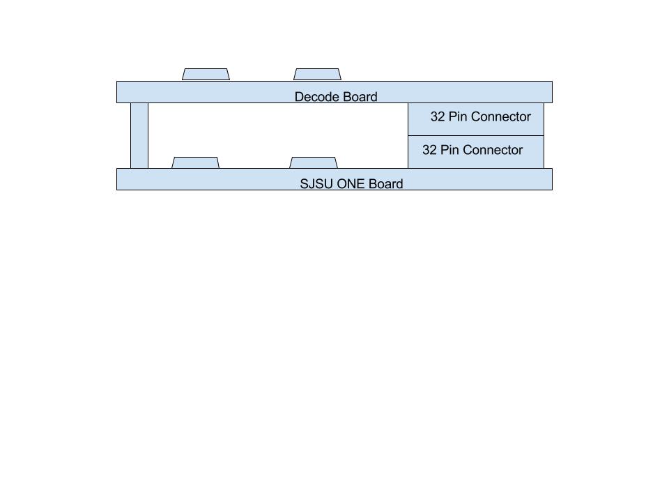
The Decode Board
The decode board is a custom board whose function is to receive raw MP3 formatted data and decode it for digital to analog conversion.
File:Decode Board Top Level.jpg
Hardware Design
Discuss your hardware design here. Show detailed schematics, and the interface here.
The Master board and receiver boards are SJSU ONE boards used in standard configurations.
The Decode board is a custom build PCB. The Decode board consists of three functions: MP3 Decode, DAC, and Voltage Regulator, as well as a 34 pin connector.
MP3 Decode
The MP3 Decode board uses a STA013 MP3 Decoder chip. A detailed data sheet can be found at: STA013 MP3 Decoder
We used the standard configuration suggested by the manufacturer. The manufacturer suggests all signals from 5 volt boards and all 5 volt supplies be stepped down to 3 volts. Since the signals from the SJSU ONE board are in the 3 volt range, and power is supplied by the SJSU ONE board, we did not have to implement the any voltage step downs.
DAC
The DAC chosen for this design is the CS4334, which is the one recommended by the MP3 Decode manufacturer. A detailed data sheet can be found at: CS4334 DAC
The speakers are battery powered, so the connection to the speakers does not require power.
Voltage Regulator
The voltage regulator chosen for this board is the LM7805, configured using the standard application configuration. A detailed data sheet can be found at: LM7805 Voltage Regulator
PCB Layout
The PCB is a 2 layer board designed to plug into the SJSU ONE board connector directly.
The PCB layout
Hardware Interface
In this section, you can describe how your hardware communicates, such as which BUSes used. You can discuss your driver implementation here, such that the Software Design section is isolated to talk about high level workings rather than inner working of your project.
There are four hardware communication interfaces in the Sound Buddy: SD card reading; Nordic wireless transmission; I2C bus communication between the Receiver board and the Decode board.
SD Card Reading The Sound Buddy reads the SD card using an SPI bus interface. The Sound Buddy will assume MP3 standard files are on the SD card. The rate at which the SD card is read is ???, this allows for reformatting of the data for transfer over the Nordic wireless communication link.
Nordic Wireless The maximum data transfer rate for the Nordic wireless is 250 Kbps. The Sound Buddy operates near this maximum.
I2C Bus Communication The I2C communication delivers, at minimum, 128 Kbps to the decode board. This means the Sound Buddy is capable of delivering radio quality sound. Sound Buddy is capable of reading ITunes MP3 standard (256 Kbps) but play quality is limited to 128 Kbps.
Software Design
Show your software design. For example, if you are designing an MP3 Player, show the tasks that you are using, and what they are doing at a high level. Do not show the details of the code. For example, do not show exact code, but you may show psuedocode and fragments of code. Keep in mind that you are showing DESIGN of your software, not the inner workings of it.
Implementation
This section includes implementation, but again, not the details, just the high level. For example, you can list the steps it takes to communicate over a sensor, or the steps needed to write a page of memory onto SPI Flash. You can include sub-sections for each of your component implementation.
Testing & Technical Challenges
Proto-Type
Describe the challenges of your project. What advise would you give yourself or someone else if your project can be started from scratch again? Make a smooth transition to testing section and described what it took to test your project.
Include sub-sections that list out a problem and solution, such as:
My Issue #1
Discuss the issue and resolution.
Conclusion
Conclude your project here. You can recap your testing and problems. You should address the "so what" part here to indicate what you ultimately learnt from this project. How has this project increased your knowledge?
Project Video
Upload a video of your project and post the link here.
Project Source Code
References
Acknowledgement
Any acknowledgement that you may wish to provide can be included here.
References Used
List any references used in project.
- Wiki Page Development
- Project
- Nordic Wireless
- MP3 Decoder


