Difference between revisions of "F15: Smart Car"
Proj user22 (talk | contribs) (→Implementation) |
Proj user22 (talk | contribs) (→Hardware Interface) |
||
| Line 182: | Line 182: | ||
#'''I2C''' - HMC5883L Compass | #'''I2C''' - HMC5883L Compass | ||
#'''SPI''' - LED matrix | #'''SPI''' - LED matrix | ||
| + | #'''PWM''' - Motors | ||
=== Software Design === | === Software Design === | ||
Revision as of 01:36, 19 December 2015
Contents
Grading Criteria
- How well is Software & Hardware Design described?
- How well can this report be used to reproduce this project?
- Code Quality
- Overall Report Quality:
- Software Block Diagrams
- Hardware Block Diagrams
- Schematic Quality
- Quality of technical challenges and solutions adopted.
Project Title
Smart Car
Abstract
A smart car with three wheels will be designed to have the capability of following high contrast lines. Options for the lines include using black Sharpie, black duct tape, and white duct tape. Afterwards, it will send back a CSV file format with 0s and 1s. 1s denote that the car was traveling in the area of the map. Using a peripheral compass, the car will also be able to draw a map of the route that it took.
Objectives & Introduction
Our objectives include the following:
- Self-driving car that is able to follow a line
- LED matrix that can draw out the path the car is taking
Team Members & Responsibilities
- Steven Hwu
- B.S. Computer Engineering
- Helen Tsui
- B.S. Computer Engineering
Schedule
| Week# | Date | Task | Actual |
|---|---|---|---|
| 1 | 10/23 | Complete project abstract | Complete |
| 2 | 10/30 | Gather parts | Complete |
| 3 | 11/06 | Program compass | Complete |
| 4 | 11/13 | Program LED matrix | Complete |
| 5 | 11/20 | Program wireless functionality | Complete |
| 6 | 11/27 | Build car | Complete |
| 7 | 12/04 | Put all the pieces together | Complete |
| 8 | 12/11 | Testing | Incomplete |
Parts List & Cost
| Quantity | Description | Price |
|---|---|---|
| 2 | SJ-One development board | $80 ea |
| 1 | Cardboard | $0 ea |
| 1 | White duct tape | $4.52 ea |
| 1 | Electric tape | $1.99 ea |
| 1 | Servos | $4.47 |
| 1 | Compass | $ |
| 2 | Motors | $80~ |
| 2 | LED matrix | $24.95 ea |
| 2 | Photo transistors | $1.20 ea |
| 3 | Jumper cables | $3.99 ea |
| 1 | Super glue | $3.99 ea |
| 1 | Breadboard | $6.49 ea |
| 4 | NPN transistors | $3.29 ea |
| 1 | 5k potentiometer | $2.29 ea |
| 1 | Switch | $2.99 ea |
| _______ | ||
| Estimated total | $ |
Design & Implementation
Hardware Design
Discuss your hardware design here. Show detailed schematics, and the interface here.
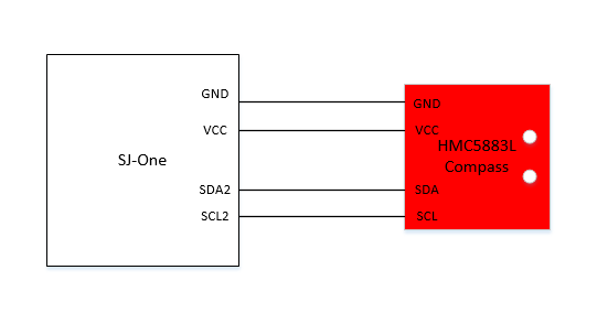
Compass
The compass uses I2C as the communication protocol. The x, y, and z coordinates were able to be read from the compass depending on its orientation. After one of the SJSUOne boards reads the x, y, and z values from the compass, it wirelessly sends the values to the other board to determine which LEDs to light up. The compass' purpose was to determine the car's location so that the path the car was taking could be drawn on the LED matrix.
LED Matrix
The purpose of the LED matrix was to display the path that the car is traveling. It uses SPI as its communication protocol.
Motors
SJOne
The SJOne the microprocessor used for this project. The compass and LED matrix were interfaced with the SJOne board. The compass used I2C while the LED matrix used SPI. The wireless functionality of the board was also utilized to in order to send information from one board to another.
Hardware Interface
Communication protocols used:
- I2C - HMC5883L Compass
- SPI - LED matrix
- PWM - Motors
Software Design
The software design utilizes drivers such as SPI and I2C. In addition to the drivers, Nordic wireless functionality was programmed.
Implementation
System Startup
Transmission of x and y Coordinates
Mapping Received Coordinates to LED Matrix
Testing & Technical Challenges
Wireless LED Matrix Testing
To test the LED matrix wirelessly, a sender task was written to allow the sending of three parameters that correlated to the coordinates of each LED on the LED matrix. If the sending was successful, the corresponding LED would light up.
Issues Faced
Wireless communication and LED Matrix
The LED matrix that was used was programmed using SPI0. However, it turns out that SPI0 is shared with the wireless communication API. To fix the issue, the LED matrix was reprogrammed on SPI1.
Conclusion
Conclude your project here. You can recap your testing and problems. You should address the "so what" part here to indicate what you ultimately learnt from this project. How has this project increased your knowledge?
Project Video
Upload a video of your project and post the link here.
Project Source Code
References
Acknowledgement
We would like to acknowledge Charles MacDonald for his help.
References Used
List any references used in project.
Appendix
You can list the references you used.
