Difference between revisions of "S15: Motion-Controlled RC Car"
(→Appendix) |
(→Acknowledgement) |
||
| Line 146: | Line 146: | ||
== References == | == References == | ||
=== Acknowledgement === | === Acknowledgement === | ||
| − | |||
| − | |||
| − | |||
| − | |||
=== References Used === | === References Used === | ||
Revision as of 07:50, 25 May 2015
Contents
Grading Criteria
- How well is Software & Hardware Design described?
- How well can this report be used to reproduce this project?
- Code Quality
- Overall Report Quality:
- Software Block Diagrams
- Hardware Block Diagrams
- Schematic Quality
- Quality of technical challenges and solutions adopted.
Motion-Controlled RC Car
Abstract
The Motion-Controlled RC Car will allow inexperienced users to drive a high-performance RC vehicle. This is accomplished with a tilt controller, which is more intuitive than a traditional RC transmitter, and a speed-limiting system that will reduce the potential for crashes.
Objectives & Introduction
Show list of your objectives. This section includes the high level details of your project. You can write about the various sensors or peripherals you used to get your project completed.
Team Members & Responsibilities
- Shangming Wang - Mesh Communication, Report writing,
- Daniel Khawaja - Wheel speed capture, RC car maintenance
Schedule
| Week# | Date | Task | Actual | Problems |
|---|---|---|---|---|
| 0 | 4/10 | Obtain hardware | Completed 4/5, excluding purchase of wheel speed sensors. | The base car (purchased used) required quite a few replacement parts |
| 1 | 4/20 | Find PWM parameters, Test mesh communication | PWM: 4/15 Mesh: pending | The servo and speed controller use pulse length instead of duty cycle |
| 2 | 4/27 | Implement PWM control, Finalize mesh communication, Test code for wheel speed capture | PWM: Mesh: Capture: | Problems Encountered? |
| 3 | 5/4 | Implement motion control, Modify RC for 2wd and mount wheel speed sensors | Motion: Modification: | Problems Encountered? |
| 3 | 5/11 | Finish wheel speed capture, Test and polish traction control parameters | Capture: T.C.: | Problems Encountered? |
| 3 | 5/18 | Study for finals, Implement extra features | Completed? hopefully. | Problems Encountered? |
Parts List & Cost
| Qty | Description | Total Cost |
|---|---|---|
| 50 | Jumper Wires | $3.00 |
| 1 | Prototype Board | $1.00 |
| 1 | Turnigy 500mAh Battery | $40.00 |
| 2 | Wireless Antenna | $6.00 |
| 1 | Remote Control Car | $150.00 |
| 2 | SJOne Board | $160.00 |
| 2 | Motorola MOC7821 Photo Interrupter | $4.00 |
| Total Cost | $364 |
Design & Implementation
Hardware Design
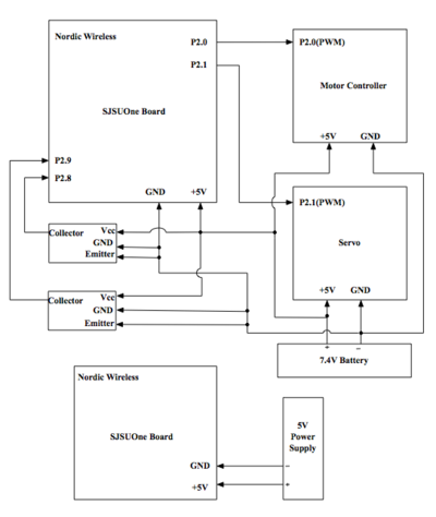
A high-level schematic of the electronics involved in this project
Our hardware design began with connecting the Sj-One board with the servo and motor controller controller that were built into the model car. The motor controller included a 5v regulated output, so that was used to power all the electronics on the vehicle.
Hardware Interface
In this section, you can describe how your hardware communicates, such as which BUSes used. You can discuss your driver implementation here, such that the Software Design section is isolated to talk about high level workings rather than inner working of your project.
Software Design
Show your software design. For example, if you are designing an MP3 Player, show the tasks that you are using, and what they are doing at a high level. Do not show the details of the code. For example, do not show exact code, but you may show psuedocode and fragments of code. Keep in mind that you are showing DESIGN of your software, not the inner workings of it.
Implementation
Nordic Wireless sensor (nRF24L01).
The Nordic wireless sensor is built-in on SJOne Board. It used to send and receive data from one SJOne to other.
- Step 1: Configure the wireless node address and wireless channel number in sys_config.h file. (Make sure both boards have the same channel)
- Step 2: Used mesh_set_node_address() function to set both sending and receiving address. In our project, the car address is set to 300.
- Step 3: On the sending side, it used wireless_send(addr, protocol, data, size of data, max_hops) function to send the data from SJOne board.
- Step 4: On the receiving side, it used wireless_get_rx_pkt() function to catch the data coming from the wireless.
Testing & Technical Challenges
Describe the challenges of your project. What advise would you give yourself or someone else if your project can be started from scratch again? Make a smooth transition to testing section and described what it took to test your project.
Include sub-sections that list out a problem and solution, such as:
My Issue #1
Discuss the issue and resolution.
Conclusion
Conclude your project here. You can recap your testing and problems. You should address the "so what" part here to indicate what you ultimately learnt from this project. How has this project increased your knowledge?
Project Video
Upload a video of your project and post the link here.
Project Source Code
References
Acknowledgement
References Used
http://www.nxp.com/documents/user_manual/UM10360.pdf
http://www.socialledge.com/sjsu/images/d/de/2012SJOneBoardSchematic.pdf
http://www.datasheetspdf.com/PDF/MOC7821/613725/1
http://www.socialledge.com/sjsu/index.php?title=PWM_Motor_Controller_Interface
http://www.socialledge.com/sjsu/index.php?title=SJ_One_Board
http://www.socialledge.com/sjsu/index.php?title=Low_Powered_Mesh_Network_stack
