Difference between revisions of "SJ One Board"
(→External SPI Devices) |
(→Board IO) |
||
| Line 34: | Line 34: | ||
Notes: | Notes: | ||
| − | * Xbee uses UART3 | + | * Xbee uses UART3 (P4.28 and P4.29) |
| − | * COMM pins can be used as GPIO, UART or CAN. | + | * COMM pins can be used as GPIO, UART, I2C or CAN. |
| + | * SPI0 uses P0.15(SCK), P0.17(MISO), P0.18(MOSI) | ||
== Board Schematic == | == Board Schematic == | ||
Revision as of 22:57, 14 September 2012
Contents
Introduction
This article provides details of the SJ-One Board used by San Jose State University.
Contact Preet if you need to get one of these boards.
LPC1758 User Manual
Board Features :
- LPC1758 CPU - 512K ROM, 64K RAM
- 8 Switches and 8 LEDs (both hard-wired)
- Temperature Sensor
- 3-Axis Acceleration Sensor
- IR Sensor for Remote Controls
- Light Sensor
- 2-Digit 7Segment Display
- RTC Crystal with Backup Battery
- SD Card and 1Mb SPI Flash.
- Socket for Xbee or Wifi Module (Uart3)
- 18 GPIOs with SPI, Multiple UARTs, and I2C availability
- Power from USB or External Power
Potential Future Board Changes
- Reduce Switches and LEDs from 8 to 4 to expose 8 contiguous GPIO
- Add Nordic Wireless SPI Interface
Board Block Diagrams
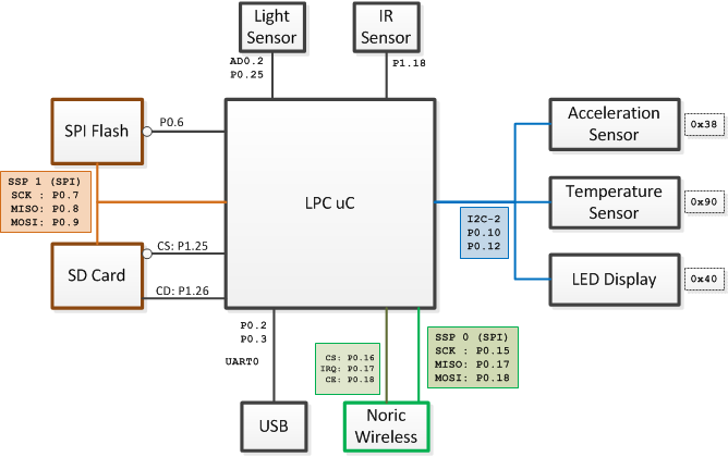
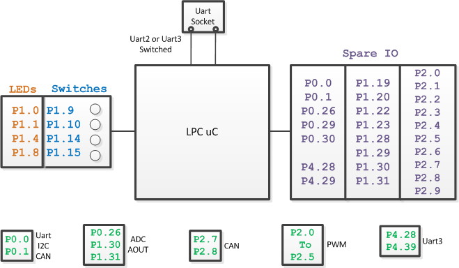
The block diagrams below show the connectivity to various different chips on the PCB, and also show which GPIOs are available to you. The first diagram shows the pins used for on-board sensors or interfaces. The second diagram shows IOs you can use.
Board Connections
Board IO
Notes:
- Xbee uses UART3 (P4.28 and P4.29)
- COMM pins can be used as GPIO, UART, I2C or CAN.
- SPI0 uses P0.15(SCK), P0.17(MISO), P0.18(MOSI)
Board Schematic
Download the PDF Schematic here:
File:2012SJOneBoardSchematic.pdf
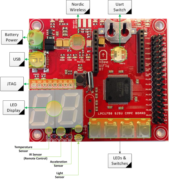
Board Overlay
This board overlay can be compared against diagrams above to get an idea of where the IOs are located.
External SPI Devices
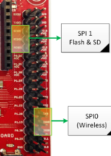
To hook up your external SPI device(s), use SPI#1 connections because there is already a driver in SJ-One sample project for this SPI. See the connections below and the sample code:
#include "spi1.h"

void access_my_spi_device()
{
   // Send 0xDEAD over to SPI device and get 2 bytes back:
   chip_select_my_device(true);
   {
       char byte_0 = spi1_ExchangeByte(0xDE);
       char byte_1 = spi1_ExchangeByte(0xAD);
   }
   chip_select_my_device(false);

   /**
    * You can use any GPIO for CS (chip-select) signal.
    * This example assumes CS is done through a function:
    *   chip_select_my_device(bool);
    */
}
External I2C Devices
I2C#2 is tied to on-board sensors and you should utilize I2C 2's connection to hook up external I2C devices. See the connections below and the sample code:
#include "I2C2.hpp"

void send_byte_to_my_i2c_device()
{
    const char my_dev_addr = 0xBA; // Your device address
    const char my_dev_reg  = 0x01; // Write to 1st register of your device
    const char my_dev_data = 0xAB; // Write 0xAB to reg 0x01
    I2C2::getInstance().writeReg(my_dev_addr, my_dev_reg, my_dev_data);
}


