Difference between revisions of "S15: Wireless Mesh Network"
Proj user8 (talk | contribs) (→Design & Implementation) |
Proj user8 (talk | contribs) m (→Hardware Design) |
||
| Line 125: | Line 125: | ||
=== Hardware Design === | === Hardware Design === | ||
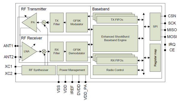
| − | Wireless mesh network is achieved using Nordic nRF24L01 transceiver. The hardware schematic of the chip is taken from the datasheet. The pins CE, SCN, SCK, MOSI, MISO and IRQ are connected to the CPU pins. The electrical connections between the CPU and wireless transceiver are taken from ''SJOne_lpc1758_rev4.pdf''. The detailed hardware schematic is shown in figure 4. The block diagram of nRF24L01 is shown in figure 5. | + | Wireless mesh network is achieved using Nordic nRF24L01 transceiver. The hardware schematic of the chip is taken from the datasheet. The pins CE, SCN, SCK, MOSI, MISO and IRQ are connected to the CPU pins. The electrical connections between the CPU and wireless transceiver are taken from ''SJOne_lpc1758_rev4.pdf''. The detailed hardware schematic is shown in figure 4. The block diagram of nRF24L01 from the datasheet is shown in figure 5. |
[[File:S15_wirelessmesh_nordic_hardware.jpg|400px|thumb|left|text-top|Fig 4. Hardware Schematic of nRF24L01]] | [[File:S15_wirelessmesh_nordic_hardware.jpg|400px|thumb|left|text-top|Fig 4. Hardware Schematic of nRF24L01]] | ||
[[File:S15_wirelessmesh_nordic_blockdiagram.png|600px|thumb|right|text-top|Fig 5. Block diagram of nRF24L01]] | [[File:S15_wirelessmesh_nordic_blockdiagram.png|600px|thumb|right|text-top|Fig 5. Block diagram of nRF24L01]] | ||
| − | |||
| − | |||
| − | |||
| − | |||
| − | |||
| − | |||
| − | |||
| − | |||
| − | |||
| − | |||
| − | |||
| − | |||
| − | |||
| − | |||
| − | |||
| − | |||
| − | |||
| − | |||
| − | |||
| − | |||
| − | |||
| − | |||
| − | |||
| − | |||
| − | |||
| − | |||
| − | |||
| − | |||
| − | |||
=== Hardware Interface === | === Hardware Interface === | ||
Revision as of 03:57, 4 May 2015
Contents
Grading Criteria
- How well is Software & Hardware Design described?
- How well can this report be used to reproduce this project?
- Code Quality
- Overall Report Quality:
- Software Block Diagrams
- Hardware Block Diagrams
- Schematic Quality
- Quality of technical challenges and solutions adopted.
Project Title
Wireless Mesh Network
Abstract
A mesh network topology is a design in which each node in the network is connected to at least two other nodes in the network. Communication between two nodes is established without a internet connection. Each node in the network can talk to every other node in the network by exchanging a payload data. An important feature of mesh network is that there is no single point of failure(SPoF), i.e. data is transmitted via an alternative route even if a node in the network fails. In this project we are implementing a wireless mesh network using Nordic wireless on SJOne boards. Each SJOne board acts as a node in the wireless mesh network. Features such as self-healing, shortest path routing, address nodes with auto-replies, and node participation are implemented to as to make the communication more reliable.
Objectives & Introduction
The wireless mesh network is achieved through the built-in Nordic Wireless interface. Each board acts as a node in the wireless mesh network which sends and receives information. The following objectives are to be implemented:
- Self-healing
- Shortest path routes
- Address nodes with auto-retries
- Each node participation
Mesh networks play an important part in the Internet of Things(IoT). Mesh networks can use a full mesh topology or a partial mesh topology. In full mesh topology, each node is connected to every other node in the network and in a partial mesh topology at least one node is connected to every other node and the rest of the nodes are connected to the nodes that they frequently exchange data with. Wired mesh network pose several constraints. Each node in the network has to be physically connected to every other node. The advancement of wireless mesh networks simplifies this approach.
A Wireless Mesh Network(WMN) is a communication network made up of radio nodes organized in a mesh topology. It was originally developed for the military communication. A typical wireless mesh network consists of mesh clients, mesh routers, and gateways. In this project the SJOne boards are the mesh clients. Mesh routers route traffic from the gateways, which can happen over the internet. A mesh cloud comprises of the area covered by the radio nodes working as a single network. A mesh network is highly reliable, during transmission if a node fails, the data is sent to the other node through a redirected path. The data is transmitted from one node to other in hops through the intermediate nodes. Each intermediate nodes maintains a routing table which includes information about the network topology, destination node, source node and next hop. A routing table is a database which keeps track of the path and assists the intermediate node in delivering the information from source to the destination.
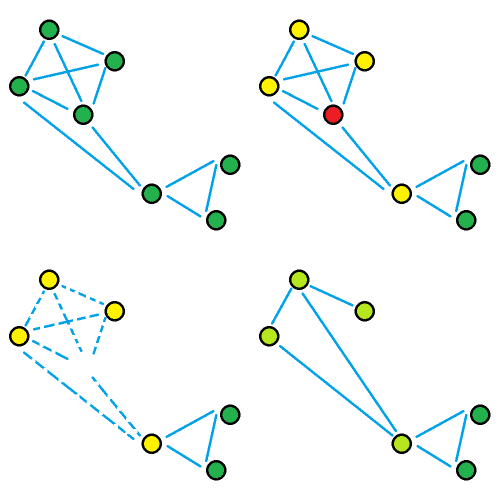
Self-healing is a technique in which a new connection is formed between the nodes in case of a failure such as a node moving out of scope due to external or internal disturbances. This ensures that the data is transmitted to the destination node through a new path even if there is any conflict in the established path. This technique is demonstrated through a gif in figure 3. The node in red is the node which is destroyed, a communication link is established between the other two nodes ensuring reliable transmission of data.
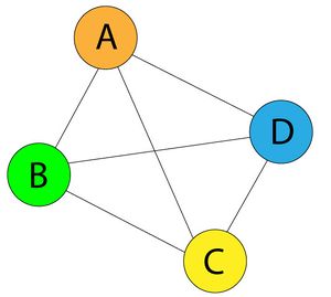
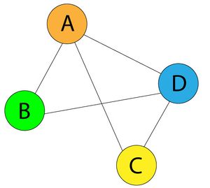
Shortest path routes is a technique in which the message from node A to node B is delivered through the shortest possible path in the network. Suppose in the mesh network shown in figure 1, if node A wants to send the data to node C, it will directly send it to C instead of routing it through B or D.
Team Members & Responsibilities
1. Akhil Bhargav Josyabhatla
- Software implementation
2. Dheeraj Dake
- Software implementation
3. Manideep Kurumella
- Software implementation
4. Vishnu Vardhana Reddy Mandalapu
- Software implementation
Schedule
Show a simple table or figures that show your scheduled as planned before you started working on the project. Then in another table column, write down the actual schedule so that readers can see the planned vs. actual goals. The point of the schedule is for readers to assess how to pace themselves if they are doing a similar project.
| Week | Dates | Challenges | Comments |
|---|---|---|---|
| 1 | 3/31 - 4/7 | Mesh network overview | Completed |
| 2 | 4/7 - 4/14 | ANT network overview | Completed |
| 3 | 4/14 - 4/21 | To test communication between the boards using Nordic wireless | Completed (Packet Loss) |
| 4 | 4/21 - 4/28 | To send packets using addressing techniques | To be done |
| 5 | 4/28 - 5/5 | To test the shortest path using all possible configurations | To be done |
| 6 | 5/5 - 5/12 | Implement self healing and re-transmission mechanisms | To be done |
| 7 | 5/12 - 5/19 | Testing | To be done |
| 8 | 5/19 - 5/25 | More testing and final demo | To be done |
Parts List & Cost
| Item | Price | Quantity | Price |
|---|---|---|---|
| SJ One Board | $80 | 4 | $320 |
| Antenna | $3 | 4 | $12 |
| Total | $332 |
Design & Implementation
The design section can go over your hardware and software design. Organize this section using sub-sections that go over your design and implementation.
Hardware Design
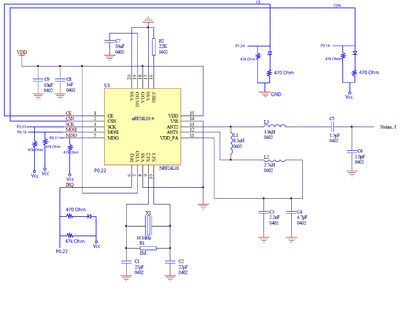
Wireless mesh network is achieved using Nordic nRF24L01 transceiver. The hardware schematic of the chip is taken from the datasheet. The pins CE, SCN, SCK, MOSI, MISO and IRQ are connected to the CPU pins. The electrical connections between the CPU and wireless transceiver are taken from SJOne_lpc1758_rev4.pdf. The detailed hardware schematic is shown in figure 4. The block diagram of nRF24L01 from the datasheet is shown in figure 5.
Hardware Interface
In this section, you can describe how your hardware communicates, such as which BUSes used. You can discuss your driver implementation here, such that the Software Design section is isolated to talk about high level workings rather than inner working of your project.
Software Design
Show your software design. For example, if you are designing an MP3 Player, show the tasks that you are using, and what they are doing at a high level. Do not show the details of the code. For example, do not show exact code, but you may show psuedocode and fragments of code. Keep in mind that you are showing DESIGN of your software, not the inner workings of it.
Implementation
This section includes implementation, but again, not the details, just the high level. For example, you can list the steps it takes to communicate over a sensor, or the steps needed to write a page of memory onto SPI Flash. You can include sub-sections for each of your component implementation.
Testing & Technical Challenges
Describe the challenges of your project. What advise would you give yourself or someone else if your project can be started from scratch again? Make a smooth transition to testing section and described what it took to test your project.
Include sub-sections that list out a problem and solution, such as:
My Issue #1
1. Huge packet loss while transmitting packets using Nordic wireless
Conclusion
Conclude your project here. You can recap your testing and problems. You should address the "so what" part here to indicate what you ultimately learnt from this project. How has this project increased your knowledge?
Project Video
Upload a video of your project and post the link here.
Project Source Code
References
Acknowledgement
Any acknowledgement that you may wish to provide can be included here.
References Used
List any references used in project.
Appendix
You can list the references you used.
