Difference between revisions of "F24: Tilt Maze"
Proj user4 (talk | contribs) (→MP3 Decoder) |
Proj user4 (talk | contribs) (→MP3 Decoder) |
||
| Line 401: | Line 401: | ||
|- | |- | ||
|} | |} | ||
| + | |||
| + | </td> | ||
| + | <td> | ||
| + | [[File:MP3 Decoder.jpg|400px|thumb|left|LED Matrix Front]] | ||
| + | </td> | ||
| + | <td> | ||
=== Hardware Interface === | === Hardware Interface === | ||
Revision as of 23:06, 22 December 2024
Contents
Abstract
Tilt Maze is a motion-controlled puzzle game that challenges players to navigate a luminous ball through procedurally generated mazes using device tilting mechanics. Players must reach the exit within time constraints while maneuvering around obstacles and collecting power-ups that provide temporary advantages. The game combines physical device control with strategic gameplay elements, offering high replayability through its randomized level design and emphasizing skills in balance, spatial reasoning, and quick decision-making.
Objectives & Introduction
The Tilt Maze Game combines hardware and software to create an interactive puzzle experience. It uses an ADXL345 accelerometer for tilt-based movement control, navigating a character through a maze displayed on a 64x64 LED matrix. FreeRTOS manages concurrent tasks like accelerometer input, display updates, and game logic, ensuring smooth and responsive gameplay. Game states, collision detection, and immersive audio feedback via an MP3 decoder enhance the experience. Semaphores and mutexes ensure thread-safe resource management, while debug outputs provide insights during development. This project demonstrates advanced integration of peripherals and real-time systems in a cohesive gaming application.
TEAM MEMBERS AND RESPONSIBILITIES
- Shreya Belide
- Developed code for MP3 Decoder Driver to play background music and sound effects.
- Designed and implemented Game Architecture and State Machine logic.
- Developed collision detection logic to ensure smooth player interactions.
- Bug fixes in MP3 integration with FreeRTOS tasks.
- Integrated subsystems including audio, display, and game logic.
- Code Cleanup and Optimization.
- Game Packaging and Presentation Preparation.
- Jyoshna Mallineni
- Developed Accelerometer Driver for tilt-based control.
- Designed Maze Layouts and Game Graphics.
- Implemented logic for dynamic player movement and boundary restrictions.
- Developed and tested display rendering functions for the LED Matrix.
- Debugged issues with accelerometer sensitivity and movement logic.
- Assisted in subsystem integration and game logic testing.
- Code Cleanup and Documentation.
- Pavan Charith Devarapalli
- Developed LED Matrix Driver for rendering the game visuals.
- Implemented multi-level gameplay logic and player progression.
- Designed logic for traps and goal conditions in the maze.
- Integrated MP3 Decoder with SPI communication for audio playback.
- Debugged synchronization issues between subsystems.
- Tested and verified power supply stability for all components.
- Assisted with subsystem integration and final game testing.
- Managed Git Repository and Final Report Preparation.
Schedule
| Week# | Start Date | End Date | Task | Status |
|---|---|---|---|---|
| 1 |
|
|
|
|
| 2 |
|
|
|
|
| 3 |
|
|
|
|
| 4 |
|
|
|
|
| 5 |
|
|
|
|
| 6 |
|
|
|
|
| 7 |
|
|
|
|
| 8 |
|
|
|
|
| 9 |
|
|
|
|
| 10 |
|
|
|
|
BILL OF MATERIALS
| Part | # | Cost | Source |
|---|---|---|---|
| SJ2 Board | 1 | $50.00 | Preet |
| Sparkfun RGB (64x64) LED Matrix Display | 1 | $32.72 | Amazon |
| Accelerometer | 1 | $10.99 | Amazon |
| 12v DC Power Jack Adapter Connector | 1 | $8.90 | Amazon |
| MP3 Decoder | 1 | 6.90 | Amazon |
| Packaging | 1 | $12 | Target |
| Jumper Wires | 1 | $6.99 | Amazon |
| Total Cost | $128.5 |
Design & Implementation
The design section can go over your hardware and software design. Organize this section using sub-sections that go over your design and implementation.
Hardware Design
Discuss your hardware design here. Show detailed schematics, and the interface here.
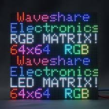
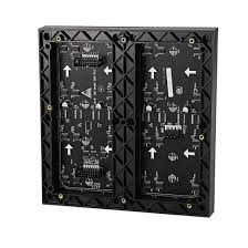
RGB LED MATRIX
It is composed of two upper and lower sectional LED pannels. Each pannel has R, G, B led channels and A, B, C, and D row control registers. Addtionally, column shift is controlled by Latch bit, clock is controled by CLK, and OE turns LED off when switching rows.
|
Connectivity Table LED Matrix to Sj2 Board:
|
Accelerometer
|
Connectivity Table LED Matrix to Sj2 Board:
MP3 Decoder
|


