Difference between revisions of "F24: Bounce Tales"
Proj user8 (talk | contribs) (→Interfacing and Layout) |
Proj user8 (talk | contribs) (→Hardware Design) |
||
| Line 336: | Line 336: | ||
|[[File:Board.PNG|450px|thumb|right|Board Layout]] | |[[File:Board.PNG|450px|thumb|right|Board Layout]] | ||
|} | |} | ||
| + | |||
| + | === '''LED Matrix''' === | ||
| + | A 64x64 RGB LED Matrix, with a total of 4096 pixels is used for display. Each LED can be fully controlled independently using 13 digital GPIOs. This matrix has six 64-bit shift registers for R1, G1, B1 R2, G2, B2 where each color of the LED is controlled by one bit of the shift register. By combing RGB colors we can make different colors such as YELLOW, CYAN, RED, WHITE, MAGENTA. | ||
| + | ==== Technical Specifications==== | ||
| + | |||
| + | {| class="wikitable" style="text-align: center; width: 400px; height: 200px;" | ||
| + | |- | ||
| + | ! Specification | ||
| + | ! Remarks | ||
| + | |- | ||
| + | | Pitch || 3 mm | ||
| + | |- | ||
| + | | Resolution || 64x64 =4096 pixels | ||
| + | |- | ||
| + | | Volt/Amp || 5V/60A | ||
| + | |- | ||
| + | | Scan Rate|| 1/16 | ||
| + | |- | ||
| + | |} | ||
| + | |||
| + | ====LED Matrix Panel==== | ||
| + | {| | ||
| + | |[[File:RGB_Led_matrix.jpg|600px|thumb|right|RGB LED Matrix]] | ||
| + | |[[File:Start_screen.jpg|500px|thumb|left|Start Screen]] | ||
| + | |} | ||
| + | === '''Dual Axis Joystick''' === | ||
| + | We have used a 2-axis joystick to control the movements of the jumper. The joystick operates on 5V power and provides analog output, hence it is connected to the ADC pins of the SJtwo-c board. The joystick has two potentiometers, each for X-axis and Y-axis. X-axis values are used to define the left and right directions of the jumper. The switch on the joystick controls the start and stop actions of the game. | ||
| + | |||
| + | [[File:D_joystick.jpg|500x280px |thumb|center|Dual Axis Joystick]] | ||
| + | |||
| + | === '''MP3 Decoder''' === | ||
| + | The MP3 decoder that we used is serial MP3 player model by Catalex (version v1.0.1). It's a simple MP3 player device which is based on a high-quality MP3 audio chip---YX5300. It can support 8k Hz ~ 48k Hz sampling frequency MP3 and WAV file formats. There is a TF card socket on board, so you can plug the micro SD card that stores audio files. MCU can control the MP3 playback state by sending commands to the module via UART port, such as switch songs, change the volume and play mode and so on. | ||
| + | |||
| + | [[File:MP3 Decoder.PNG|500x280px |thumb|center|MP3 Decoder]] | ||
=== Software Design === | === Software Design === | ||
Revision as of 19:21, 19 December 2024
Contents
Grading Criteria
- How well is Software & Hardware Design described?
- How well can this report be used to reproduce this project?
- Code Quality
- Overall Report Quality:
- Software Block Diagrams
- Hardware Block Diagrams
- Schematic Quality
- Quality of technical challenges and solutions adopted.
Project Title
Bounce Tales
Abstract
Bounce Tales is a classic mobile game reminiscent of the Nokia era, featuring a bouncing character navigating through levels filled with obstacles. This project aims to recreate the game experience using the SJ-2 board and an LED matrix display. Players will control the character’s movement using buttons or a joystick, while the game will include levels, obstacles, and scoring. The implementation will focus on real-time movement, collision detection, and level progression.
Objectives & Introduction
The idea is to build the bounce tales game on a 64x64 RGB LED Screen. The game is played using a joystick. The ball keeps on collecting the point avoiding the obstacles and its direction can be controlled using left and right control of the joystick, which can also be used in forward direction jump to avoid the obstacles. MP3 decoder is used for different sound effects in the background of game.
Team Members & Responsibilities
- Vaidehi
- LED driver
- Game Logic
- PCB design verification
- WiKi page handling
- Shashank
- MP3 decoder driver
- Game Logic
- PCB Schematic and Board Design
- WiKi page handling
- Manvendra
- Joystick driver
- Game Logic
- PCB design verification
- WiKi page handling
Schedule
| Week# | Start Date | End Date | Task | Status |
|---|---|---|---|---|
| 1 |
|
|
|
|
| 2 |
|
|
|
|
| 3 |
|
|
|
|
| 4 |
|
|
|
|
| 5 |
|
|
|
|
| 6 |
|
|
|
|
| 7 |
|
|
|
|
| 8 |
|
|
|
|
| 9 |
|
|
|
|
| 10 |
|
|
|
|
Parts List & Cost
| Item# | Part Name | Part Supplier | Quantity | Cost |
|---|---|---|---|---|
| 1 |
64x64 RGB LED Matrix |
Amazon |
1 |
$ 87.4 |
| 2 |
Sjtwo board |
Amazon |
1 |
$ 50 |
| 3 |
Two-axis Joystick |
Amazon |
1 |
$ 4.25 |
| 4 |
MP3 Decoder |
Amazon |
1 |
$ 8.05 |
| 5 |
Power Supply |
Amazon |
1 |
$ 7.99 |
Design & Implementation
Hardware Design
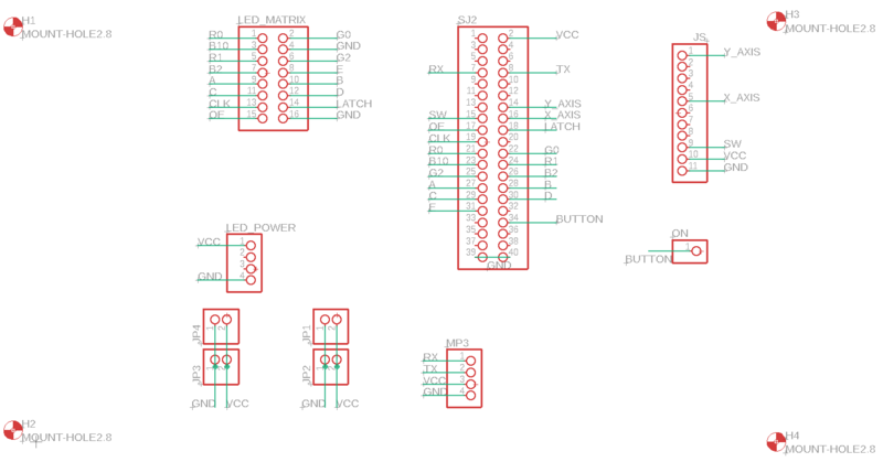
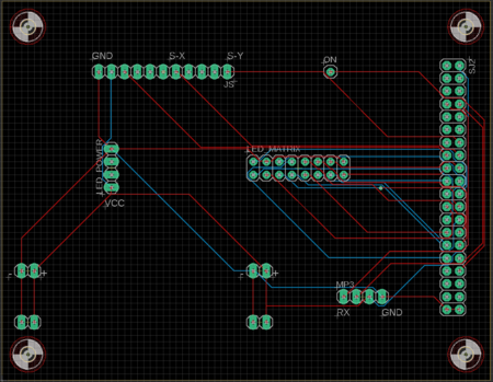
The game has been designed using SJtwo-c board, RGB LED- for visuals, MP3 decoder- for background music, joystick and PCB. The game is controlled by using a two-axis joystick and to play the music we have used an MP3 decoder.
PIN Configuration
| PIN number | Pin Description | SJTwo Board Pin |
|---|---|---|
| LED Matrix | ||
| R1 | Upper half (Section 1) | p2_0 |
| G1 | Upper half (Section 1) | p2_1 |
| B1 | Upper half (Section 1) | p2_2 |
| R2 | Lower half (Section 2) | p2_4 |
| G2 | Lower half (Section 2) | p2_5 |
| B2 | Lower half (Section 2) | p2_6 |
| A | Address Line | p2_7 |
| B | Address Line | p2_8 |
| C | Address Line | p2_9 |
| D | Address Line | p0_16 |
| E | Address Line | p0_15 |
| GND | Connected to ground | GND |
| Clk | For upper half and lower half | p1_28 |
| Latch | For upper half and lower half | p1_23 |
| OE | For upper half and lower half | p1_20 |
| Joystick | ||
| S-X | X axis data | p0_30 |
| S-Y | Y axis data | p1_25 |
| S-K | Switch data | p1_31 |
| MP3 Decoder | ||
| RX | Receiver | p4_29 |
| TX | Transmitter | p4_28 |
| VCC | connected to vcc | 5V |
| GND | Connected to ground | GND |
Interfacing and Layout
LED Matrix
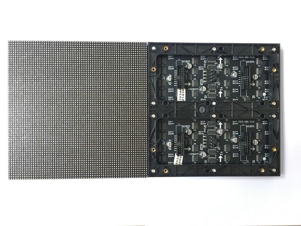
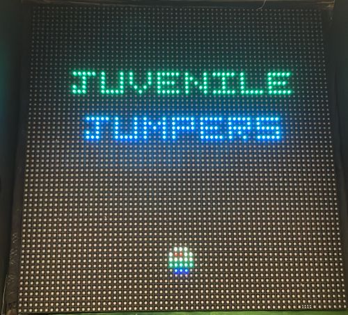
A 64x64 RGB LED Matrix, with a total of 4096 pixels is used for display. Each LED can be fully controlled independently using 13 digital GPIOs. This matrix has six 64-bit shift registers for R1, G1, B1 R2, G2, B2 where each color of the LED is controlled by one bit of the shift register. By combing RGB colors we can make different colors such as YELLOW, CYAN, RED, WHITE, MAGENTA.
Technical Specifications
| Specification | Remarks |
|---|---|
| Pitch | 3 mm |
| Resolution | 64x64 =4096 pixels |
| Volt/Amp | 5V/60A |
| Scan Rate | 1/16 |
LED Matrix Panel
Dual Axis Joystick
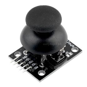
We have used a 2-axis joystick to control the movements of the jumper. The joystick operates on 5V power and provides analog output, hence it is connected to the ADC pins of the SJtwo-c board. The joystick has two potentiometers, each for X-axis and Y-axis. X-axis values are used to define the left and right directions of the jumper. The switch on the joystick controls the start and stop actions of the game.
MP3 Decoder
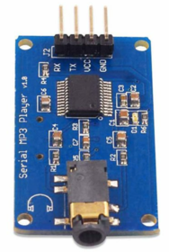
The MP3 decoder that we used is serial MP3 player model by Catalex (version v1.0.1). It's a simple MP3 player device which is based on a high-quality MP3 audio chip---YX5300. It can support 8k Hz ~ 48k Hz sampling frequency MP3 and WAV file formats. There is a TF card socket on board, so you can plug the micro SD card that stores audio files. MCU can control the MP3 playback state by sending commands to the module via UART port, such as switch songs, change the volume and play mode and so on.
Software Design
Show your software design. For example, if you are designing an MP3 Player, show the tasks that you are using, and what they are doing at a high level. Do not show the details of the code. For example, do not show exact code, but you may show psuedocode and fragments of code. Keep in mind that you are showing DESIGN of your software, not the inner workings of it.
Implementation
This section includes implementation, but again, not the details, just the high level. For example, you can list the steps it takes to communicate over a sensor, or the steps needed to write a page of memory onto SPI Flash. You can include sub-sections for each of your component implementation.
Testing & Technical Challenges
Describe the challenges of your project. What advise would you give yourself or someone else if your project can be started from scratch again? Make a smooth transition to testing section and described what it took to test your project.
Include sub-sections that list out a problem and solution, such as:
<Bug/issue name>
Discuss the issue and resolution.
Conclusion
Conclude your project here. You can recap your testing and problems. You should address the "so what" part here to indicate what you ultimately learnt from this project. How has this project increased your knowledge?
Project Video
Upload a video of your project and post the link here.
Project Source Code
References
Acknowledgement
Any acknowledgement that you may wish to provide can be included here.
References Used
List any references used in project.
Appendix
You can list the references you used.
