Difference between revisions of "S22: Silver Arrow"
Proj user5 (talk | contribs) (→Mobile Application) |
Proj user5 (talk | contribs) (→Mobile Application) |
||
| Line 423: | Line 423: | ||
<Picture and link to Gitlab> | <Picture and link to Gitlab> | ||
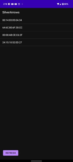
| − | [[File:App_bt_list.jpg| | + | [[File:App_bt_list.jpg|250px]] |
=== Hardware Design === | === Hardware Design === | ||
Revision as of 21:58, 22 May 2022
Contents
Project Title
<Team Name>
Abstract
<2-3 sentence abstract>
Introduction
The project was divided into N modules:
- Sensor ...
- Motor..
- ...
- Android
Team Members & Responsibilities
Pushkar Deodhar LinkedIn
- App development
- Mechanical/Hardware/circuit/PCB designing
Vilas Dhuri LinkedIn\
- Driver Logic
- Hardware and PCB designing
Rishabh Gupta LinkedIn
- Driver Logic
- Wiki page manage
Vivek Tapkir LinkedIn
- Sensor controller
- Communication Bridge Controller
- Hardware Integration
Saharash Shivahre LinkedIn
- Geo controller
- Wiki page manage
Naveena Sura LinkedIn
- Geo controller
- Git repo managment
Daya Modekar LinkedIn
- Motor controller
- Hardware Integration and design
Schedule
| Week# | Start Date | End Date | Task | Status |
|---|---|---|---|---|
| 1 | 03/16/2022 | 03/22/2022 |
|
|
| 2 |
03/23/2022
|
03/29/2022
|
|
|
| 3 |
03/30/2022
|
03/04/2022
|
|
|
| 4 |
04/05/2022
|
04/11/2022
|
|
|
| 5 |
04/12/2022
|
04/18/2022
|
|
|
| 6 |
04/19/2022
|
04/25/2022
|
|
|
Parts List & Cost
| Item# | Part Desciption | Vendor | Qty | Cost |
|---|---|---|---|---|
| 1 | RC Car | Traxxas | 1 | $250.00 |
| 2 | CAN Transceivers MCP2551-I/P | Microchip [1] | 8 | Free Samples |
Printed Circuit Board
<Picture and information, including links to your PCB>
CAN Communication
<Talk about your message IDs or communication strategy, such as periodic transmission, MIA management etc.>
Hardware Design
<Show your CAN bus hardware design>
DBC File
<Gitlab link to your DBC file> <You can optionally use an inline image>
Sensor ECU
<Picture and link to Gitlab>
Hardware Design
Software Design
<List the code modules that are being called periodically.>
Technical Challenges
< List of problems and their detailed resolutions>
Motor ECU
Hardware Design
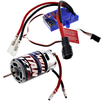
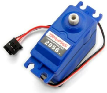
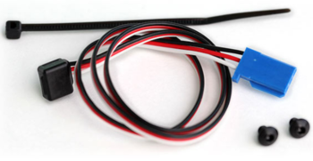
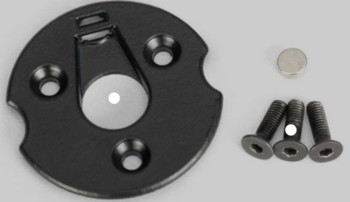
Motor Controller Node includes the operational control of the DC motor, Servo motor, Electronic speed control (ESC), and the wheel encoder(RPM Sensor). The job of the motor controller is to control the steering of front wheels at appropriate angles and to spin the rear wheels at speeds commanded by the driver node in order to traverse the RC car to the destination location.The DC motor, servo motor, and ESC(Traxxas ESC XL-05) were provided with the Traxxas RC car. The wheel encoder and the trigger magnet were purchased separately from Traxxas's website.
| SJ2 Board Pin | Description |
|---|---|
| 5V | Input power |
| 3.3V | CAN transceiver power |
| PWM2 P2.1 | DC Motor Speed Control |
| PWM5 P2.4 | Servo Motor Angle Control |
| CAP0 P2.6 | RPM Sensor\Wheel Encoder |
| CAN1 TX | CAN Transceiver Tx |
| CAN1 RX | CAN Transceiver Rx |
| GND | Grounding |
DC Motor and ESC
The DC motor is controlled by the ESC using PWM signals which were provided by the motor controller board for forward, neutral, and reverse movements.The DC motor and ESC were provided with RC car.The ESC is powered ON using a 7.4 LiPo battery.The ESC converts this 7.4V to 6V and provides input to DC Motor.
| ESC wires | Description | Wire Color |
|---|---|---|
| Vout | Output Power (6V) | RED |
| GND | Ground | BLACK |
| PWM | PWM input from SJ2-Board (P2.1) | WHITE |
The car can be operated at 100Hz in the following 3 modes :
Sport Mode (100% Forward, 100% Brakes, 100% Reverse)
Racing Mode (100% Forward, 100% Brakes, No Reverse)
Training Mode (50% Forward, 100% Brakes, 50% Reverse)
Servo Motor
The servo motor responds to PWM pulses. It has three pins namely Vcc, PWM Input Signal, and GND. The servo is powered using 6V from the car battery. Based on the PWM signal supplied from the SJTwo board the front wheels are turned.
| Servo Wires | Description | Wire Color |
|---|---|---|
| Vin | Input Voltage (6V) | RED |
| GND | Ground | BLACK |
| PWM | PWM input from SJ2-Board (P2.4) | WHITE |
The PWM frequency for our Traxxas Servo motor also needed to be 100Hz. An idle (wheel's pointing forward) duty cycle is 15%. The full duty cycle range is [10%, 20%], where [10%, 15%) is the steer left range, and (15%, 20%] is the steer right.
Wheel Encoder
For speed sensing we purchased a Traxxas RPM sensor as it mounted nicely in the gearbox. The RPM sensor works by mounting a magnet to the spur gear and a hall effect sensor fixed to the gearbox. To get the revolutions per second we used Timer2 as an input capture.
| RPM Sensor Wires | Description | Wire Color |
|---|---|---|
| Vin | Input Voltage (6V) | RED |
| GND | Ground | BLACK |
| Sensor Output | Input Capture to SJ2-Board (P2.6) | WHITE |
Software Design
The motor controller code modules consisted of 3 main parts, which are: 1. PWM drivers and motor logic, 2. RPM/speed sensor, 3. PID controller.
Technical Challenges
- First and foremost, the Traxxas motor ESC and other Traxxas components are Traxxas Hobby Parts, and they are not designed for development. As a result, no technical specification documentation or program/development guidelines are accessible. The motor ESC must be tested by supplying PWM duty cycles in different sequences at different duty cycle percentages. We utilized the remote control to recreate certain circumstances in which the ESC acted strangely.
- If a Lipo battery is used, the ESC setup switches to the Lipo battery state. When the NiMH battery is replaced, the ESC begins flashing the led in a green-red pattern, and the ESC power button stops working. In this case, the handbook contains a calibration procedure that can rescue your boat and restore regular ESC operation.
- Another challenge with the motor node program development is that you cannot rely on unit testing. Whoever works on the motor node, should make sure that the sequence of the duty cycles being fed to the ESC produces the expected results on the motor as well. The forward-reverse transitioning and the speed controlling both can be a bit tricky. Also, the hard brake logic can take a while to get working properly.
- We somehow destroyed the ESC and wanted to replace it. We spent both time and money on this. Make sure you don't short the ESC by mistake!
Geographical Controller
<Picture and link to Gitlab>
Hardware Design
Software Design
<List the code modules that are being called periodically.>
Technical Challenges
< List of problems and their detailed resolutions>
Communication Bridge Controller & LCD
<Picture and link to Gitlab>
Hardware Design
Software Design
<List the code modules that are being called periodically.>
Technical Challenges
< List of problems and their detailed resolutions>
Master Module
<Picture and link to Gitlab>
Hardware Design
Software Design
<List the code modules that are being called periodically.>
Technical Challenges
< List of problems and their detailed resolutions>
Mobile Application
https://gitlab.com/naveena.sura/silver-arrow/-/merge_requests/8 <Picture and link to Gitlab>
Hardware Design
Google Pixel 6 mobile was used to run the application and HC-05 Bluetooth Module was used to establish communication between the application and Bridge Controller
Software Design
The software's main front-end code was written in Kotlin. We used Bluetooth communication for transferring and receiving data over the application. Before we open the application, we first need to pair the HC-05 Bluetooth module with the mobile. This is done by going to the mobile’s Bluetooth Setting and pairing the module. The application has 3 “activities”. Activity 1: Bluetooth Connection Screen When the app first opens the Bluetooth socket that is created is checked if it is NULL, which it should be with a start-up. If this occurs the Bluetooth connection screen will be brought up, and the user will need to tap a device to attempt a connection. If the connection fails, the screen will again be brought up. Once the connection is successfully established, we move on to the next “Activity 2: Maps Activity”
Activity 2: Maps Activity: The Google Map SDK is so large and has so many capabilities, we created an account on Google Cloud Console, enabled the API, and then utilized the API key in the Android App's Manifest file. In this activity, we have set up 3 “OnClickListners” viz. My Location, North Align, Send Destination Coordinates. If the user clicks on to “My Location” icon and if the Mobile’s location is “On”, then the map will transport itself to the current location of the mobile. The user can zoom in and out like any other GoogleMaps application and click anywhere on the map to drop a pin. If the user again taps onto the pin, then it will show the coordinates of the selected dropped pin. When the user clicks on “Send Destination Coordinates” the coordinates of the dropped pin are sent over Bluetooth to the Bridge Controller, and the app goes to the final activity “Activity 3: CarDataDisplaActivity”.
Activity 3: CarDataDisplayActivity: This is a very simple activity. All this activity does that it shows the various data that are sent over the CAN bus on the car and displays it live on the app. The application receives the data over the HC-05 Bluetooth module in a long comma (,) separated string format and then segregates the data into the respective fields. Few of the data that are displayed on the application include all the sensor values, current car speed, distance remaining towards the destination, etc. Lastly, this activity has two buttons to start and stop the car. <List the code modules that are being called periodically.>
Technical Challenges
< List of problems and their detailed resolutions>
Conclusion
<Organized summary of the project>
<What did you learn?>
Project Video
Project Source Code
Advise for Future Students
<Bullet points and discussion>
