Difference between revisions of "S22: TBD"
(→CAN Communication) |
(→Hardware Design) |
||
| Line 328: | Line 328: | ||
=== Hardware Design === | === Hardware Design === | ||
| − | We used 4 Gravity DFRobot URM09 ultrasonic sensors. These ultrasonic sensors are used by the RC car for the purpose of obstacle avoidance. They use I2C communication to send distance data to the SJ2 microcontroller. The measurement range is 300cm. It takes in 3.3V supply voltage. Using the I2C driver the registers on the ultrasonic sensors were configured and the distance was read from the specified registers in the datasheet. | + | We used 4 Gravity DFRobot URM09 ultrasonic sensors. These ultrasonic sensors are used by the RC car for the purpose of obstacle avoidance. They use I2C communication to send distance data to the SJ2 microcontroller. The measurement range is 300cm. It takes in 3.3V supply voltage. Using the I2C driver the registers on the ultrasonic sensors were configured and the distance was read from the specified registers in the datasheet. |
| + | |||
| + | <br> | ||
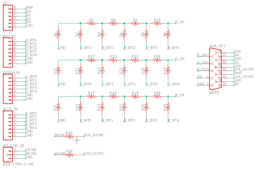
| + | [[File:pcbSchematic.png|500px|thumb|left|PCB Schematic]] | ||
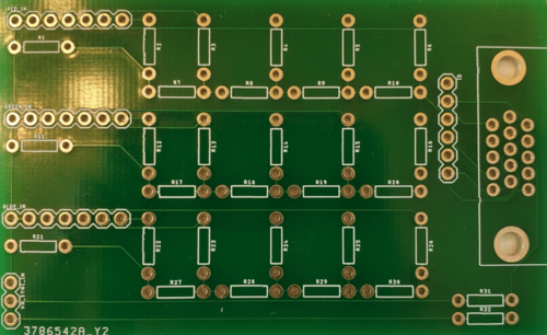
| + | [[File:pcbLayout.png|500px|thumb|right|PCB Layout]] | ||
| + | [[File:pcbPic-min.png|500px|thumb|right|Manufactured PCB]] | ||
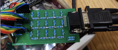
| + | [[File:pcbManufactured.png|500px|thumb|left|Soldered PCB]] | ||
| + | <br> | ||
| + | |||
=== Software Design === | === Software Design === | ||
<List the code modules that are being called periodically.> | <List the code modules that are being called periodically.> | ||
Revision as of 22:58, 1 May 2022
Contents
Project Title
<TBD>
Abstract
<2-3 sentence abstract>
Introduction
The project was divided into 5 modules:
- Sensor
- Motor
- Geo Controller
- Driver/LCD Controller
- Web application
Team Members & Responsibilities
<Team Picture>
Gitlab Project Link - [1]
<Provide ECU names and members responsible> <One member may participate in more than one ECU>
- Sensor
- Brian Ho
- Jasdip Sekhon
- Motor
- Billy Lai
- Link to Gitlab user2
- Geographical
- Justin Stokes
- Link to Gitlab user2
- Communication Bridge Controller & LCD
- Isaac Wahhab
- Link to Gitlab user2
- Android Application
- Link to Gitlab user1
- Link to Gitlab user2
- Testing Team
- Billy Lai
- Link to Gitlab user2
Schedule
| Week# | Start Date | End Date | Task | Status |
|---|---|---|---|---|
| 1 | 02/15/2022 | 02/21/2022 |
|
Completed |
| 2 | 02/22/2022 | 02/28/2022 |
|
Completed |
| 3 | 03/01/2022 | 03/07/2022 |
|
Completed |
| 4 | 03/08/2022 | 03/14/2022 |
|
Completed |
| 5 | 03/15/2022 | 03/21/2022 |
|
Completed |
| 6 | 03/22/2022 | 03/28/2022 |
|
Completed |
| 7 | 03/29/2022 | 04/04/2022 |
|
Completed |
| 8 | 04/05/2022 | 04/11/2022 |
|
Completed |
| 9 | 04/12/2022 | 04/18/2022 |
|
Completed |
| 10 | 04/19/2022 | 04/25/2022 |
|
In Progress |
| 11 | 04/26/2022 | 05/02/2022 |
|
In Progress |
| 12 | 05/03/2022 | 05/09/2022 |
|
Incomplete |
| 13 | 05/10/2022 | 05/16/2022 |
|
Incomplete |
| 14 | 05/17/2022 | 05/25/2022 |
|
Incomplete |
Parts List & Cost
| Item# | Part Desciption | Vendor | Qty | Cost |
|---|---|---|---|---|
| 1 | RC Car | Redcat Racing [2] | 1 | $139.00 |
| 2 | CAN Transceivers (SN65HVD230) | Waveshare [3] | 4 | $10.00 |
Printed Circuit Board
<Picture and information, including links to your PCB>
CAN Communication
<Talk about your message IDs or communication strategy, such as periodic transmission, MIA management etc.>
Our message IDs are arranged with priority given to the nodes in the following order: DRIVER, SENSOR, GEO, MOTOR.
We decided to give 32 message IDs to each node and to separate the nodes' message IDs accordingly.
| Node | Message ID Range | |
|---|---|---|
| 1 | DRIVER | 32 - 63 |
| 2 | SENSOR | 63 - 95 |
| 3 | GEO | 96 - 127 |
| 4 | MOTOR | 128 - 159 |
Hardware Design
<Show your CAN bus hardware design>
DBC File
Gitlab link to our master branch's DBC file
Our DBC file includes the SENSOR, DRIVER, MOTOR, and GEO nodes.
Below are the messages defined in the file:
BO_ 32 DRIVER_TO_MOTOR_CMD: 1 DRIVER
SG_ DRIVER_TO_MOTOR_steer : 0|3@1+ (1,-2) [-2|2] "" MOTOR
SG_ DRIVER_TO_MOTOR_speed : 3|5@1+ (1,0) [0|31] "RPM" MOTOR
BO_ 64 SENSOR_TO_DRIVER_SONARS: 3 SENSOR
SG_ SENSOR_TO_DRIVER_SONARS_front_left : 0|8@1+ (1,0) [0|0] "" DRIVER
SG_ SENSOR_TO_DRIVER_SONARS_front_middle : 8|8@1+ (1,0) [0|0] "" DRIVER
SG_ SENSOR_TO_DRIVER_SONARS_front_right : 16|8@1+ (1,0) [0|0] "" DRIVER
BO_ 65 GPS_DESTINATION_LOCATION: 8 SENSOR
SG_ GPS_DESTINATION_LOCATION_latitude : 0|28@1+ (0.000001,-90.000000) [-90|90] "Degrees" GEO
SG_ GPS_DESTINATION_LOCATION_longitude : 28|29@1+ (0.000001,-180.000000) [-180|180] "Degrees" GEO
BO_ 96 GEO_STATUS: 5 GEO
 SG_ GEO_STATUS_compass_direction : 0|9@1+ (1,0) [0|359] "Degrees" SENSOR,DRIVER
 SG_ GEO_STATUS_destination_direction : 9|9@1+ (1,0) [0|359] "Degrees" SENSOR,DRIVER
 SG_ GEO_STATUS_distance_to_destination : 18|16@1+ (0.1,0) [0|0] "Meters" SENSOR,DRIVER
BO_ 128 MOTOR_DEBUG_MSG: 1 MOTOR
SG_ MOTOR_DEBUG_MSG_echo_steer : 0|3@1+ (1,-2) [-2|2] "" DBG
SG_ MOTOR_DEBUG_MSG_echo_speed : 3|5@1+ (1,0) [0|31] "RPM" DBG
Sensor ECU
<Picture and link to Gitlab>
Hardware Design
We used 4 Gravity DFRobot URM09 ultrasonic sensors. These ultrasonic sensors are used by the RC car for the purpose of obstacle avoidance. They use I2C communication to send distance data to the SJ2 microcontroller. The measurement range is 300cm. It takes in 3.3V supply voltage. Using the I2C driver the registers on the ultrasonic sensors were configured and the distance was read from the specified registers in the datasheet.
Software Design
<List the code modules that are being called periodically.>
Technical Challenges
< List of problems and their detailed resolutions>
Motor ECU
<Picture and link to Gitlab>
Hardware Design
Software Design
<List the code modules that are being called periodically.>
Technical Challenges
< List of problems and their detailed resolutions>
Geographical Controller
<Picture and link to Gitlab>
Hardware Design
Software Design
<List the code modules that are being called periodically.>
Technical Challenges
< List of problems and their detailed resolutions>
Communication Bridge Controller & LCD
<Picture and link to Gitlab>
Hardware Design
Software Design
<List the code modules that are being called periodically.>
Technical Challenges
< List of problems and their detailed resolutions>
Master Module
<Picture and link to Gitlab>
Hardware Design
Software Design
<List the code modules that are being called periodically.>
Technical Challenges
< List of problems and their detailed resolutions>
Mobile Application
<Picture and link to Gitlab>
Hardware Design
Software Design
<List the code modules that are being called periodically.>
Technical Challenges
< List of problems and their detailed resolutions>
Conclusion
<Organized summary of the project>
<What did you learn?>
Project Video
Project Source Code
Advise for Future Students
<Bullet points and discussion>


