Difference between revisions of "S21: Roadster"
Proj user3 (talk | contribs) (→Hardware Design) |
Proj user3 (talk | contribs) (→Hardware Design) |
||
| Line 579: | Line 579: | ||
<BR/> | <BR/> | ||
<BR/> | <BR/> | ||
| + | The SJ2 board | ||
=== Software Design === | === Software Design === | ||
Revision as of 19:17, 27 May 2021
Contents
Roadster
Abstract
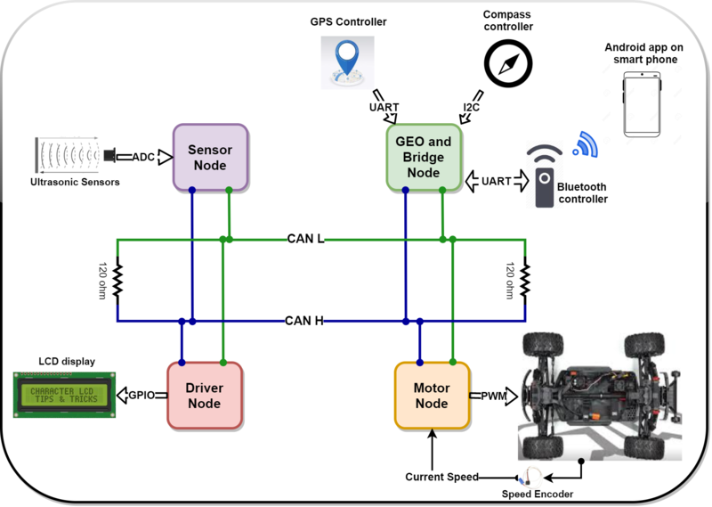
Roadster is a battery powered autonomous car, that drives itself to a specified destination and avoids any obstacles that comes its way. The car infrastructure has four Nodes (Geo, Sensor, Driver and Motor) that communicate over the CAN bus and an android application interface to set the destination location. In order to make an informed decision the car processes Geo and Sensor Node’s data which is used to steer the car in the right direction.
Introduction
The project was divided into N modules:
- Sensor Node
- Geo Node
- Driver Node
- Geo Node
- Android Application
Team Members & Responsibilities
<Team Picture>
Tejas Pidwalkar
- Sensor Node
- Driver Node
Nimit Patel
- Geo Node
Tirth Pandya
- Motor Node
- PCB design
Srikar Reddy
- Android Application
Sourab Gupta
- Driver Node
<Provide ECU names and members responsible> <One member may participate in more than one ECU>
- Sensor Node
- Link to Gitlab user1
- Link to Gitlab user2
- Geo Node
- Link to Gitlab user1
- Link to Gitlab user2
- Driver Node
- Motor Node
- Link to Gitlab user1
- Link to Gitlab user2
- Android Application
- Link to Gitlab user1
- Link to Gitlab user2
- Testing Team
- Link to Gitlab user1
- Link to Gitlab user2
Schedule
| Week# | Start Date | End Date | Task | Actual Completion | Status |
|---|---|---|---|---|---|
| 1
03/01 to 03/07 Start of Phase 1 |
|
|
|
|
|
| 2
03/08 to 03/14 |
|
|
|
|
|
| 3
03/15 to 03/21 |
|
|
|
|
|
| 4
03/22 to 03/28 |
|
|
|
|
|
| 5
03/29 to 04/04 End of Phase 1 |
|
|
|
|
|
| 6
04/05 to 04/11 Start of Phase 2 |
|
|
|
|
|
| 7
04/12 to 04/18 |
|
|
|
|
|
| 8
04/19 to 04/25 End of Phase 2 |
|
|
|
|
|
| 9
04/26 to 05/02 Start of Phase 3 |
|
|
|
|
|
| 10
05/03 to 05/09 |
|
|
|
|
|
| 11
05/10 to 05/16 End of Phase 3 |
|
|
|
|
|
Parts List & Cost
| Item# | Part Desciption | Vendor | Qty | Cost |
|---|---|---|---|---|
| 1 | RC Car | Traxxas [1] | 1 | $250.00 |
| 2 | CAN Transceivers MCP2551-I/P | Comimark [2] | 5 | $7.00 |
| 3 | Ultrasonic Sensors | Max Botix[3] | 5 | $150.00 |
| 4 | GPS and Antenna | Adafruit[4] | 1 | $60.00 |
| 5 | HC05 bluetooth RF Transreceiver | HiLetgo[5] | 1 | $12.59 |
| 6 | Triple-axis Accelerometer | Adafruit[6] | 1 | $21.40 |
| 7 | Traxxas RPM Sensor | Traxxas[7] | 1 | $12 |
| 8 | Discrete Electronic Components | Generic[8] | 1 | $28.75 |
| 9 | Buck-Boost Voltage Regulator | Generic[9] | 1 | $11.99 |
| 10 | Traxxas Telemetry Trigger magnet & holder | Traxxas[10] | 1 | $6.35 |
| 11 | Amazon[] | 1 | $ | |
| 12 | Amazon[] | 1 | $ | |
| 13 | Amazon[] | 1 | $ | |
| 14 | Amazon[] | 1 | $ |
Printed Circuit Board
<Picture and information, including links to your PCB>
CAN Communication
<Talk about your message IDs or communication strategy, such as periodic transmission, MIA management etc.>
Hardware Design
<Show your CAN bus hardware design>
DBC File
<Gitlab link to your DBC file> <You can optionally use an inline image>
Sensor ECU
<Picture and link to Gitlab>
Hardware Design
Software Design
<List the code modules that are being called periodically.>
Technical Challenges
Neighboring Sensor Interference:
As explained above, we have mounted three ultrasonic sensors in the front, and those were configured to range in continuous mode, in which sensors were continuously measuring distance by transmitting beam. Out of 3, the middle sensor is of type with wider beam to detect blind spots ahead.
Most of the time, we observed that the obstacle in the middle sensor range used also gets detected by the left/right sensor, which disturbs driving logic. This used to happen due to sensor beam interference among three sensors.
To solve this problem, we decided to trigger sensor beams in such time intervals that they won’t interfere with neighboring ones. We used the Rx pin of the sensor to trigger ranging and scheduled to trigger left and right sensor at one time and middle sensor next time. This sequence helped us avoid interference altogether.
< List of problems and their detailed resolutions>
Motor ECU
<Picture and link to Gitlab>
Hardware Design
Software Design
<List the code modules that are being called periodically.>
Technical Challenges
< List of problems and their detailed resolutions>
Geographical Controller
Repository link for Geo Controller
Hardware Design
The SJ2 board
Software Design
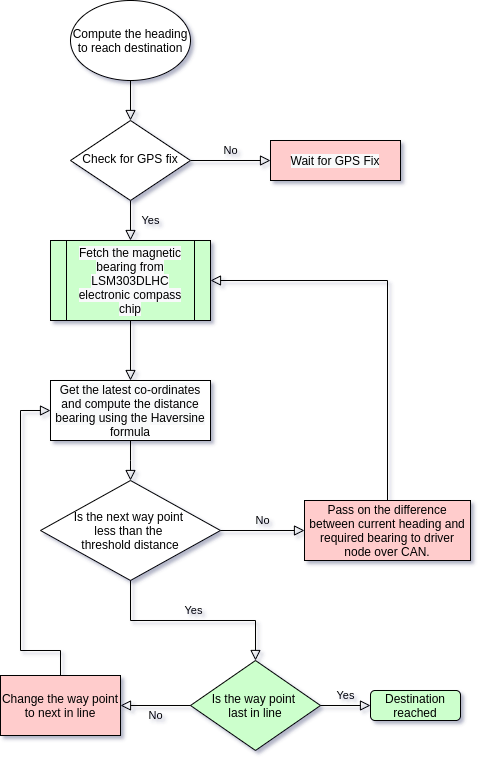
The GEO controller is divided into X parts.
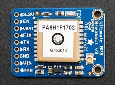
The current location of the car is determined using the GPS.
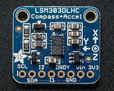
The current magnetic heading of car is determined using the on board compass.
The way point calculation determines the nearest way point continuously by computing the distance using Haversine formula and current location using GPS.
The heading is also computed using the Haversine formula and the difference between the actual and required is sent over the CAN bus for heading correction.
Alternatively, once the car is within the threshold distance, next way point is selected and the car heads to the next way point.
Technical Challenges
< List of problems and their detailed resolutions>
Communication Bridge Controller & LCD
<Picture and link to Gitlab>
Hardware Design
Software Design
<List the code modules that are being called periodically.>
Technical Challenges
< List of problems and their detailed resolutions>
Driver Node
<Picture and link to Gitlab>
Hardware Design
Software Design
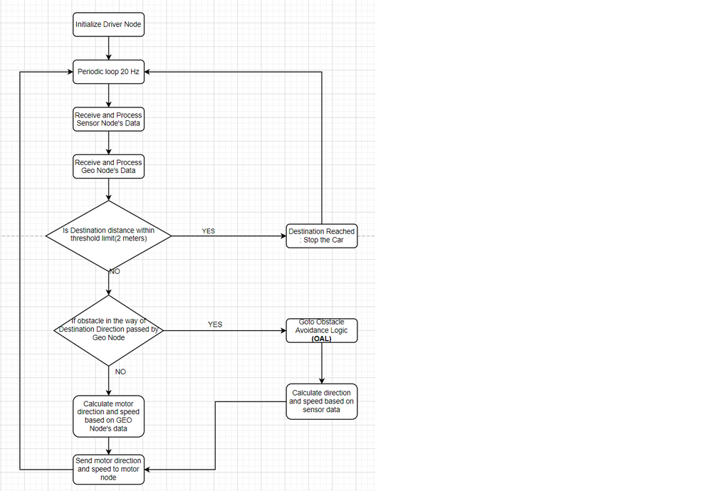
- Flow Chart
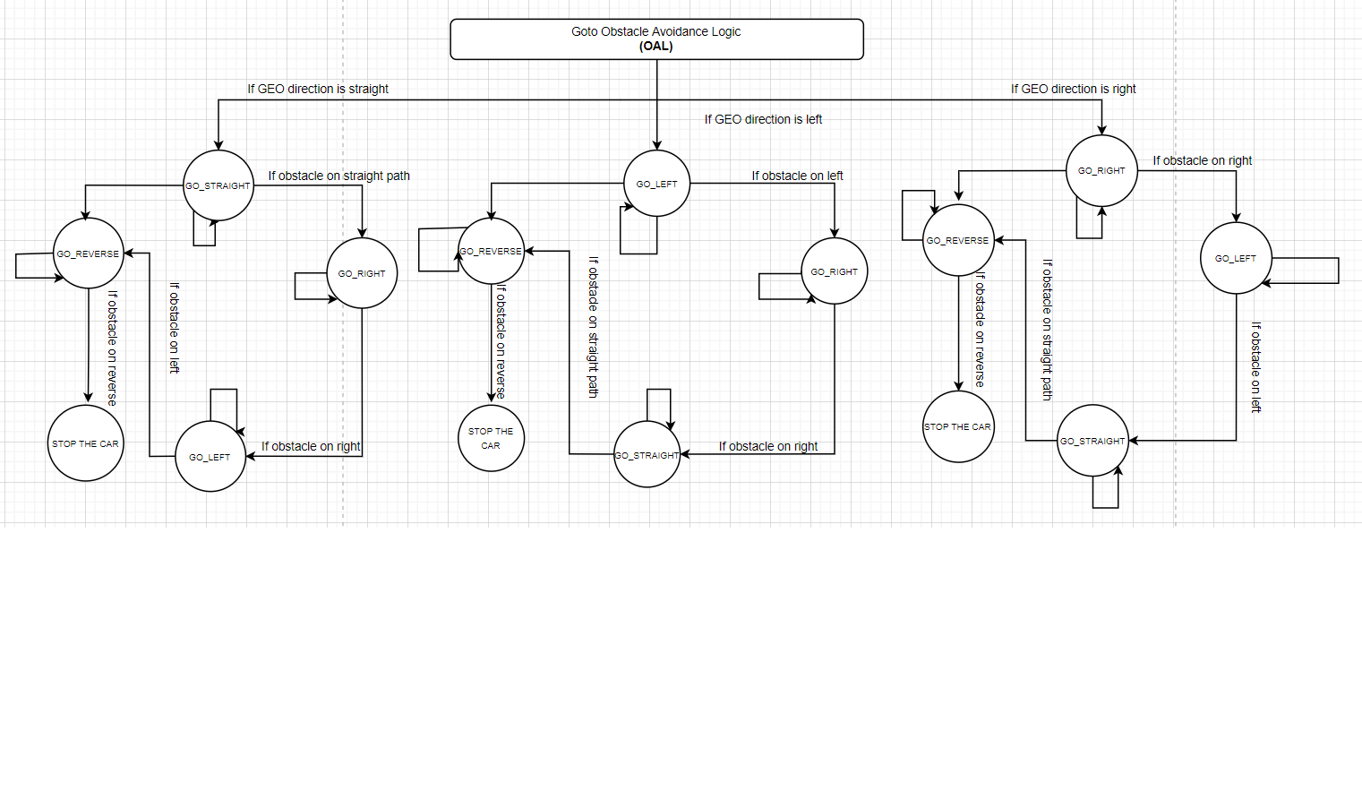
- Obstacle Avoidance Logic
- 1 Hz Loop:
- Transmit debug messages over the CAN bus
- 20 Hz Loop:
- Receive Sensor Data
- Receive Geo Data
- Process and Transmit Data(Motor Direction and Speed) to Motor Node
Technical Challenges
< List of problems and their detailed resolutions>
Mobile Application
<Picture and link to Gitlab> We created a lightweight mobile app to control our car, It can communicate with the car via Bluetooth and is capable of sending Destination co-ordinates along with checkpoints. Receive and Update live location on Google Maps, send Start, Stop and Clear commands, Receive and Display Debug Data.
Software Design
This app has mainly two activities, The main activity and maps activity.
Maps Activity
This is the only functional activity for the app and is responsible for the Google Maps and Bluetooth related Tasks. User can also dynamically select multiple checkpoints and send them to the bridge node. This is achieved using java vector and OnMapclickListener setup to read each marker placed by the user.
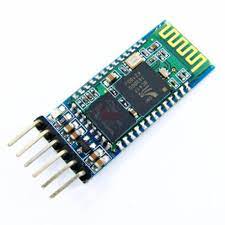
The Bluetooth connection is initially set up by reading the id and MAC addresses of the selected device, The available devices are displayed on a listView under the connect button. Bluetooth socket module provides read() and write() API used to communicate. Below is the code snippet that parses the incoming stream with location and debug data sent by the bridge node.
                   if(readMessage.indexOf("\n")>0) {
                       message = new StringTokenizer(readMessage, "\n");
                       StringTokenizer st;
                       while (message.hasMoreTokens()) {
                           st = null;
                           received_line = message.nextToken();
                           st = new StringTokenizer(received_line, ",");
                           try {
                               read = st.nextToken();
                           } catch (Exception e) {
                               continue;
                           }
                           if (read.compareTo("GPS") == 0) {
                               try {
                                   LatLng current_location = new LatLng(Double.parseDouble(st.nextToken()), Double.parseDouble(st.nextToken()));
                                   waypoint.setText(st.nextToken("\n").replace(",", ""));
                                   prev.remove();
                                   prev = mMap.addMarker(new
                                          MarkerOptions().position(current_location).anchor(0.5f,0.5f).rotation(compass_value).title("Roadster")
                                          .icon(BitmapFromVector(getApplicationContext(), R.drawable.ic_baseline_directions_car_filled_24)));
                            if (state || init) {
                                       mMap.moveCamera(CameraUpdateFactory.newLatLng(current_location));
                                       if (current_location.latitude != 0) init = false;
                                   }
                               } catch (Exception e) {
                               }
                           } else if (read.compareTo("speed") == 0) {
                               try {
                                   speed.setText(st.nextToken("\n").replace(",", "") + "m/s");
                               } catch (Exception e) {
                               }
                           } else if (read.compareTo("sens") == 0) {
                               try {
                                   left.setText(st.nextToken() + "cm");
                                   right.setText(st.nextToken() + "cm");
                                   center.setText(st.nextToken() + "cm");
                                   back.setText(st.nextToken("\n").replace(",", "") + "cm");
                               } catch (Exception e) {
                               }
                           } else if (read.compareTo("comp") == 0) {
                               try {
                                   compass.setText(st.nextToken());
                                   String compass_s=st.nextToken("\n").replace(",", "");
                                   compass_raw.setText(compass_s);
                                   compass_value =Integer.parseInt(compass_s);
                                   prev.setAnchor(0.5f,0.5f);
                                   prev.setRotation(compass_value);
                               } catch (Exception e) {
                               }
                           } else if (read.compareTo("dist") == 0) {
                               try {
                                   String dis=st.nextToken("\n").replace(",", "");
                                   distance.setText(dis+"m");
                                   //int prog=(int)Float.parseFloat(dis)%200;
                                   //progress.setProgress(prog);
                               } catch (Exception e) {
                               }
                           } else if (read.compareTo("mot") == 0) {
                               try {
                                   rps.setText(st.nextToken());
                                   pwm.setText(st.nextToken("\n").replace(",", ""));
                               } catch (Exception e) {
                               }
                           }
                           else if(read.compareTo("bat")==0){
                               try{
                                   battery.setText(st.nextToken("\n").replace(",", "")+"%");
                               }catch (Exception e){
                               }
                           }
                      }
                       readMessage="";
Hardware Design
<List the code modules that are being called periodically.>
Technical Challenges
< List of problems and their detailed resolutions>
Conclusion
<Organized summary of the project>
<What did you learn?>
Project Video
Project Source Code
Advise for Future Students
<Bullet points and discussion>
Acknowledgement
=== References ===
