Difference between revisions of "F20: Space Invaders"
Proj user1 (talk | contribs) (→BILL OF MATERIALS) |
Proj user1 (talk | contribs) (→BILL OF MATERIALS) |
||
| Line 393: | Line 393: | ||
| 1 | | 1 | ||
| $6.99 | | $6.99 | ||
| + | |- | ||
| + | ! scope="row"| 20 | ||
| + | | JST Connector Kit | ||
| + | | [https://www.amazon.com/GeeBat-460pcs-Connector-Housing-Adapter/dp/B01MCZE2HM/ref=sr_1_6?crid=21CJADE0TVMHM&dchild=1&keywords=jst+connector&qid=1608273114&s=hi&sprefix=jst+%2Ctools%2C376&sr=1-6 GeeBat 460pcs 2.54mm JST-XH Connector Kit with 2.54mm Female Pin Header and 2/3 / 4/5 / 6 Pin Housing Connector Adapter Plug (JST Connector Kit) ] | ||
| + | | 1 | ||
| + | | $9.99 | ||
|- | |- | ||
|} | |} | ||
Revision as of 06:34, 18 December 2020
Contents
- 1 SPACE INVADERS
- 2 ABSTRACT
- 3 INTRODUCTION & OBJECTIVES
- 4 SCHEDULE
- 5 BILL OF MATERIALS
- 6 PRINTED CIRCUIT BOARD
- 7 LED MATRIX
- 8 MP3 DECODER
- 9 PERIPHERALS
- 10 GAME SOFTWARE DESIGN
- 10.1 Communication
- 10.2 Project Structure
- 10.3 Game tasks
- 10.3.1 Refresh Display Task
- 10.3.2 LED Decorative Sign Task
- 10.3.3 Display Scoreboard Task
- 10.3.4 Start Screen Task
- 10.3.5 Victory Screen Task
- 10.3.6 Game Over Screen Task
- 10.3.7 Move Laser Cannon Task
- 10.3.8 Move Enemies Task
- 10.3.9 Laser Cannon Shooting Task
- 10.3.10 Enemy Shooting Task
- 10.3.11 Kill Animation Task
- 10.3.12 Play Game Sound Task (SD Card Reading)
- 10.3.13 Audio Decoder Task
- 10.3.14 Which Song to Play Task
- 10.3.15 Volume Control Task
- 10.4 Game logic high level design
- 11 3D PRINTED ENCLOSURE
- 12 TESTING & TECHNICAL CHALLENGES
- 13 CONCLUSION
- 14 ACKNOWLEDGEMENT
- 15 APPENDIX
SPACE INVADERS
ABSTRACT
Space Invaders is a fixed one person shooter style video game. The player controls a laser cannon by moving it horizontally across the bottom of the screen and firing at the aliens descending toward the cannon from the top of the screen. There are aliens descending towards the cannon and the player's main goal is to defeat an alien and earn points by shooting it with the laser cannon and destroying it. As more aliens are defeated, the aliens' movement speeds up. The alien invasion is declared successful and the game ends when the aliens have successfully reached the bottom. The final score of total kills is projected after the game ends. The mp3 decoder connected to the speaker will play the sound effects required.
INTRODUCTION & OBJECTIVES
About the Game
The object of the game is, basically, to shoot the invaders with your laser cannon while avoiding their shots and preventing an invasion. Amassing a high score is a further objective and one that must be prioritized against your continued survival. Each game screen starts with 3 rows of 4 invaders. The enemies will be shooting at the laser cannon seeking to destroy it in order to invade the earth. The person controlling the laser cannon must avoid getting blown out by the enemies. As more enemies are destroyed the difficulty increases with the speed of the enemies increasing towards the earth. The laser cannon can survive 5 enemy bullets.
Objective
- Interface the 64x64 RGB LED Matrix with SJ-Two Microcontroller.
- Interface the VS1053 MP3 Decoder with another SJ-Two Microcontroller.
- Interface MAX98357A Mono Amplifier via I2S.
- Establish UART communications between the two SJ-Two Microcontrollers.
- Create simple coding logic for displaying required characters and game objects.
- Have required sound effects at different functions of the game.
- Have multiple display screens at different stages of the game.
Team Members
Technical Responsibilities
| Administrative Roles | ||||
|---|---|---|---|---|
|
Salvatore Nicosia & Akash Vachhani | |||
|
Akhil Cherukuri | |||
|
Salvatore Nicosia | |||
|
Salvatore Nicosia & Akhil Cherukuri | |||
|
Akhil Cherukuri | |||
|
Akash Vachhani | |||
|
Salvatore Nicosia | |||
|
Salvatore Nicosia & Akhil Cherukuri | |||
Administrative Responsibilities
| Administrative Roles | ||||
|---|---|---|---|---|
|
Salvatore Nicosia | |||
|
Salvatore Nicosia & Akash Vachhani | |||
|
Salvatore Nicosia & Akash Vachhani | |||
|
Akhil Cherukuri | |||
|
Akhil Cherukuri | |||
SCHEDULE
| Week# | Start Date | End Date | Task | Status |
|---|---|---|---|---|
| 1 |
|
|
|
|
| 2 |
|
|
|
|
| 3 |
|
|
|
|
| 4 |
|
|
|
|
| 5 |
|
|
|
|
| 6 |
|
|
|
|
| 7 |
|
|
|
|
| 8 |
|
|
|
|
| 9 |
|
|
|
|
| 10 |
|
|
|
|
BILL OF MATERIALS
PRINTED CIRCUIT BOARD
Design And Architecture
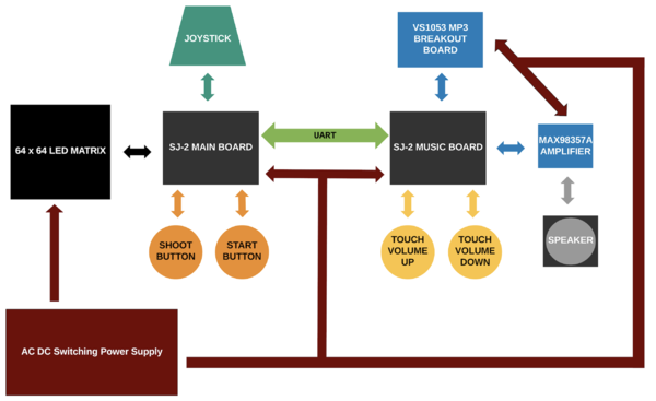
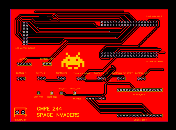
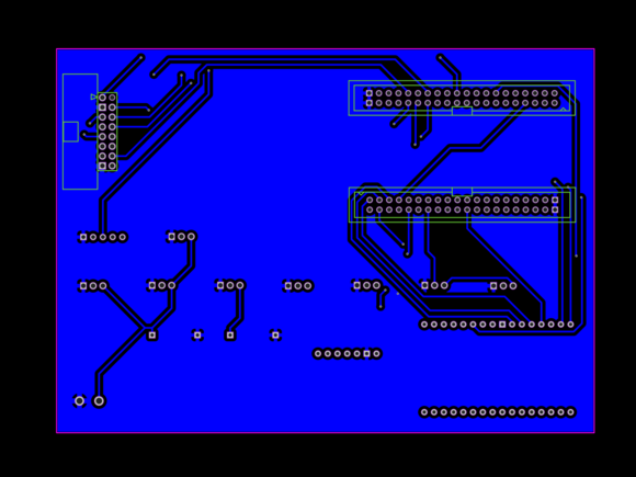
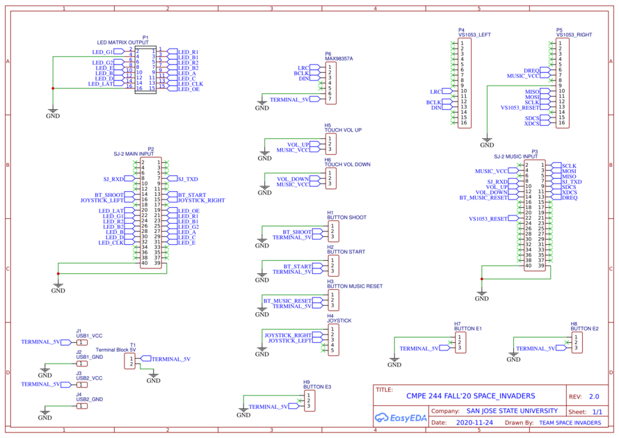
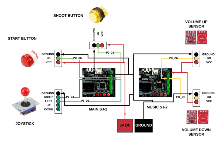
The complete printed circuit board was designed using EasyEDA online software. Implemented both SJ-Two board connectors along with required connections to buttons, led matrix, touch sensors, joystick, VS1053 MP3 Decoder, and MAX98357A I2S Amplifier.
PIN Configuration
-
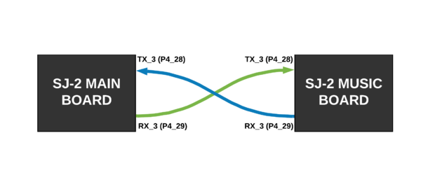
PIN# SJ-2 Main Board Pin Description uC PIN 64x64 LED MATRIX R1 PIN for Red terminal of RGB LED for the upper half of LED Matrix P2_0 G1 PIN for Green terminal of RGB LED for the upper half of LED Matrix P2_1 B1 PIN for Blue terminal of RGB LED for the upper half of LED Matrix P2_2 R2 PIN for Red terminal of RGB LED for the lower half of LED Matrix P2_4 G2 PIN for Green terminal of RGB LED for the lower half of LED Matrix P2_5 B2 PIN for Blue terminal of RGB LED for the lower half of LED Matrix P2_6 A Mux pin for row selection P2_7 B Mux pin for row selection P2_8 C Mux pin for row selection P2_9 D Mux pin for row selection P0_16 E Mux pin for row selection P0_15 OE Output Enable P1_28 LATCH Data Latch P1_29 CLK Clock Signal P0_17 POWER VCC VCC Supply VCC GND Ground GND UART TX UART Transmit P4_28 RX UART Receive P4_29 JOYSTICK Pin 2 Right Movement P1_31 Pin 3 Left Movement P1_30 BUTTONS I/0 Pin Shoot P0_25 I/0 Pin Start P0_26 -
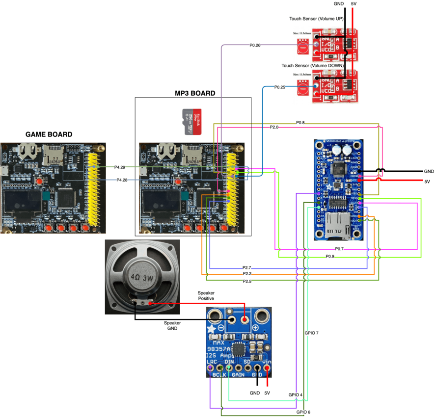
PIN# SJ-2 Music Board Pin Description uC PIN POWER VCC VCC Supply VCC GND Ground GND UART TX UART Transmit P4_28 RX UART Receive P4_29 VS1053 MP3 DECODER SCK_2 CLOCK for SPI Bus P0_7 MOSI_2 MISO for SPI Bus P0_8 MISO_2 MOSI for SPI Bus P0_9 DREQ Data Request P2_0 SDCS Transfer SCI commands P2_2 XDCS Transfer the Audio Data P2_5 RESET Reset for Decoder P2_7 GPIO 4 (I2S_LROUT) I2S Audio Out LRC GPIO 6 (I2S_SCLK) I2S Salve Clock BCLK GPIO 7 (I2S_SDATA) I2S Slave Data In DIN MAX98357A I2S MONO AMPLIFIER LRC I2S Audio Out GPIO 4 BCLK I2S Salve Clock GPIO 6 DIN I2S Slave Data In GPIO 7 BUTTONS I/0 Pin Volume Up P0_26 I/0 Pin Volume Down P0_25
Fabrication
- PCB was sent to fabrication to JLCPCB China which provided PCB with an order of 5 and 2 layers of PCB and common grounded the rest of the copper area.
DRC elements (in mm)
- Track Width = 0.254
- Clearance = 0.152
- Via Diameter = 0.61
- Via Drill Diameter = 0.305
LED MATRIX
Hardware Interface
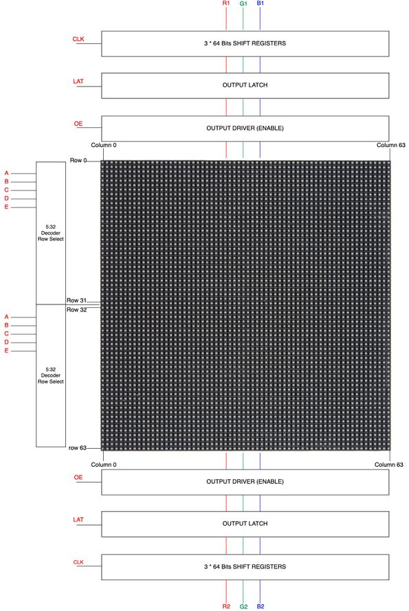
This project utilizes as a display a 64x64 RGB LED Matrix Panel with a scan rate of 1:32. The LED matrix panel has 4096 RGB LEDs which can be controlled and addressed individually. Because 4069 LEDs would be impossible to connect to the sjtwo board since it does not have sufficient GPIOs, this LED Matrix utilizes only 13 digital GPIOs to provide full control of each individual LED. To achieve this, the LED matrix uses a decoder to select the rows and a 64-bit shift register which enables the desired color on the selected column. When the row selection is low the columns are selected by clocking in data into the shift register. This 64x64 LED matrix has 6 64-bit shift registers for R1, G1, B1 R2, G2, B2 where each color of the LED is controlled by one bit of the shift register. Since this display uses shift registers which are daisy chained, there is no capability to control each LED using PWM and therefore the display only supports 8 colors. Shown below is a diagram of the LED matrix showing the top half (Rows 0-31) and bottom half (Rows 32-63) which are controlled by 5:32 decoders. These decoders have a 5-bit input for each line A, B, C, D, E and are used for row selection. The diagram also shows six shift registers R1,G1,B1 for the top half, and R2, G2, B2 and for bottom half which are used for column selection and selecting the appropriate LED color. The data is clocked into these shift registers which hold all 64 bits for every single row. The LAT (Latch) signal is used to latch the data after each color has been clocked into the shift registers so that it can reach the output driver when set to high. The latch is then closed so that the next row of data can be clocked in. The OE (Output Enable) signal is used to enable the output when this pin is low so that the LEDs are turned on showing the data previous latched. Before switching rows the OE signal is then pulled high so that no LEDs are on during this transition.
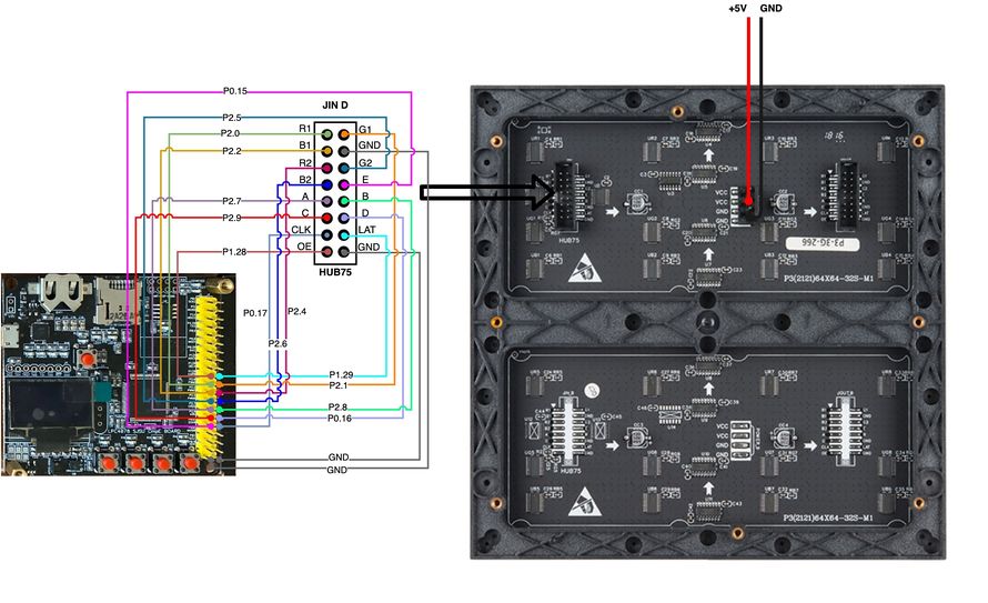
The LED matrix was interfaced with the SJTwo board using 13 GPIO pins connected to data in connector as shown in the diagram below. The LED matrix is powered by an external 5V 18amp power supply which is used for the overall system in addition to the LED matrix. The GPIO pins were chosen in such a way that they are close to each other for simplicity and wire organization.
Below are the technical specifications of the Sparkfun RGB LED Matrix Panel 64x64:
| Spec | Value |
|---|---|
| Pitch | 3mm |
| Resolution | 64 x 64 = 4096 dots |
| Panel dimensions | 192 x 192mm |
| Working voltage/current rating | 5v / 60A (max) |
| Scan Rate | 1 / 16 |
| Port Type | HUB75-A |
| Weight | 0.3 kg |
LED Matrix Driver
The LED matrix driver was designed based on the basic mechanism described below:
For each row of leds we repeat these steps:
- Set the latch and output enable pins to low to clock in the next row of data and enabling the output so that the leds are turned on
- For each column, clock in the data for the current row one bit at a time into the shift registers (R1, G1, B1, R2, G2, B2)
- Set the latch and output enable pins high to allow the row of data to reach the output driver while disabling the output so that no LEDs are on while switching rows
- Select the row by driving the appropriate row select lines (A,B,C,D,E)
Below is a snippet of code showing how the LED matrix displays the pixels based on the mechanism described before.
void led_matrix__display_pixels(void) {
  for (uint8_t row = 0; row < 32; row++) {
    led_matrix__private_disable_display();
    led_matrix__private_disable_latch();
    for (uint8_t column = 0; column < 64; column++) {
      (matrix_buffer[row][column] & 0x1) ? gpio__set(B1) : gpio__reset(B1);
      (matrix_buffer[row][column] & 0x2) ? gpio__set(G1) : gpio__reset(G1);
      (matrix_buffer[row][column] & 0x4) ? gpio__set(R1) : gpio__reset(R1);
      (matrix_buffer[row][column] & 0x8) ? gpio__set(B2) : gpio__reset(B2);
      (matrix_buffer[row][column] & 0x10) ? gpio__set(G2) : gpio__reset(G2);
      (matrix_buffer[row][column] & 0x20) ? gpio__set(R2) : gpio__reset(R2);

      led_matrix__private_clock_in_current_row_data();
    }
    led_matrix__private_enable_latch();
    led_matrix__private_enable_display();
    led_matrix__private_select_row(row);
  }
}
The LED matrix driver was written for a 64x64 display but can be easily re-adapted for other display sizes. This driver was kept as simple as possible and includes the following APIs which are available to the programmer to fully control each individual pixel. Only 8 colors are available in this driver since the LED matrix uses shift registers.
void led_matrix__clear_display(void);
void led_matrix__set_pixel(uint8_t row, uint8_t column, led_color_e color);
void led_matrix__clear_pixel(uint8_t row, uint8_t column);
The data is stored into a 32x64 buffer and in order to correctly display the colors the top and bottom half of the display use the following mask values:
static uint8_t bottom_half_of_display_mask = 0x07;
static uint8_t upper_half_of_display_mask = 0x38;
Software Design
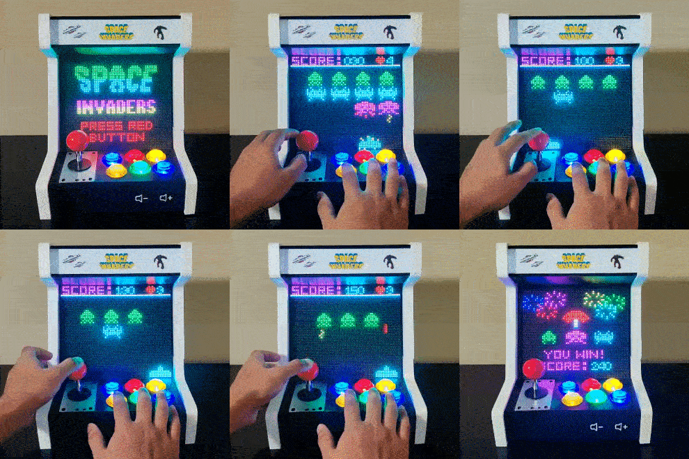
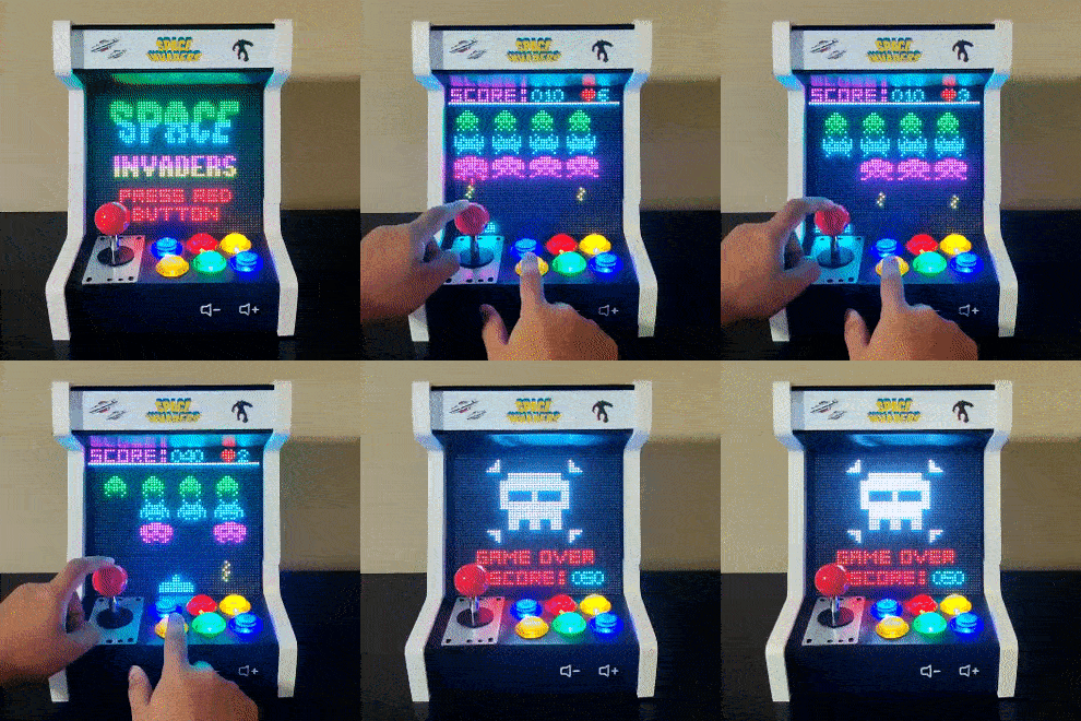
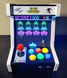
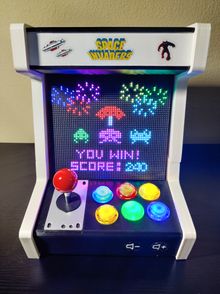
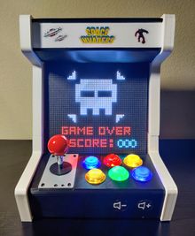
A high priority task is used to consistently refresh the LED matrix display which simply calls the led_matrix__display_pixels() API. All the game graphics and basic graphics such as numbers and letters were implemented in separate modules to keep the code base portable. The splash screen and game over screen were implemented using lookup tables and both are controlled by two separate tasks which check the status of the game and display the right screen accordingly. The victory screen was implemented by using the same graphics components used in the game logic and it also controlled by a task which checks for winning status of the game. In the images below are shown all the graphics components of the game as wells as all the different screens based on the status of the game. The graphics components of the game include, the explosion, laser cannon, enemies (octopus, crab, and squid), ufo, laser cannon bullet, enemies bullet, as well as the score board and lives. These graphics were designed by using the set_pixel() API of the LED matrix driver and it allows the user to pass in just the column position, row position, and color to display the object in the desired space of the display.
MP3 DECODER
Hardware Interface
The music portion of the game design involved the Adafruit VS1053 Breakout with SD Card. The VS1053 audio decoder is capable of decoding various music formats such as WAV, MPEG I/II, and MP3 audio types. Due to the varying audio types, the audio decoding rate can be varied depending on the song being played. The MP3 decoding hardware can use UART or SPI for the purpose of streaming music through an external source. For the purpose of this project, SPI was used and the clock rate was set to 12 Mhz to ensure a quick enough response time to send over music without any noticeable delays. The SPI bus for the MP3 decoder requires two chip selects: one for data (xdcs) and another for command registers (xcs). The xcs register allows control of registers in charge of volume, decoding mode, clock rate, and other features. The data chip select is only utilized for music data being sent into the board to be decoded. The MP3 decoder incorporates an output signal known as DREQ which is active HIGH when the SPI bus is busy. When the DREQ is low, then the SPI bus is capable of another 32 bits of data, otherwise no more data may be sent to the decoder. The MP3 decoder was connected to an I2S DAC + AMP module that allowed for external speakers to broadcast the music being decoded by the MP3 decoder. The I2S module was only capable of broadcasting audio in a mono setup(single speaker), hence why all audio files were in setup as a mono channel.
Below are the registers that were modified from their default startup value.
| Register | Modified Value |
|---|---|
| 0x0 | 0x4800 |
| 0x3 | 0xD800 |
| 0x5 | 0x2B10 |
| 0x11 | 0x0101 |
| 0xc017* | 0xF0 |
| 0xc040* | 0x0C |
Note: *Means the register value is modified by writing to the 0x7 register with the register listed in the column, followed by writing to 0x6 with the value shown in "value" column.
MP3 Decoder Driver
The MP3 Decoder driver includes 4 functions which are: mp3_decoder__init, mp3_decoder__sci, mp3_decoder__sdi, and mp3_decoder__dreq. In order for the MP3 decoder to function properly, the initialize function must be called first.
The mp3_decoder__init() function passed in four variables: xcs, xdcs, dreq, and rst. They are all of type gpio_s thus requiring a specific port and pin assigned to each variable. The steps taken to initialize the mp3_decoder__init() are:
- Assign xcs, xdcs, and dreq to their respective static variables available in the mp3_decoder.c file
- Initialize SSP1 to 12 Mhz max
- Set xcs and xdcs to high(disable them)
- Reset rst(enable), wait 2ms and set rst(disable)
- This allows the mp3 decoder breakout to restart, accepting the new SCLK rate
- Write 0x4800 to SCI_MODE register using mp3_decoder__sci. Enables VS1053 SD_New mode and active high headphones
- Write 0xD800 to SCI_CLKF register using mp3_decoder__sci. Allows a clock multiplier of 3x
- Write 0x2B10 to SCI_AUDATA register using mp3_decoder__sci. Allows for 11Hz mono audio decoding
- Write 0xc017 and 0xF0 using mp3_decoder__sci respectively to SCI_WRAMADDR and SCI_WRAM. Initial setup for I2S.
- Write 0xc040 and 0xC0 using mp3_decoder__sci respectively to SCI_WRAMADDR and SCI_WRAM. Enable MCLK and GPIO pins to be used for I2S.
void mp3_decoder__init(gpio_s xcs, gpio_s xdcs, gpio_s dreq, gpio_s rst) {

  // set xcs xdcs reset output
  // MCU outputs reset as a low, set chip selects as high
  uint32_t set_12_mhz_clock = 12 * 1000 * 1000;
  uint16_t sci_mode_register_defaults = 0x4800;
  uint16_t default_sample_11hz = 0x2B10;
  uint16_t default_clockf_divide = 0xD800;
  uint16_t default_volume_70_percent = 0x0101;
  dreq_pin = dreq;
  xdcs_pin = xdcs;
  xcs_pin = xcs;
  ssp1__initialize(set_12_mhz_clock);
  gpio__set(xcs);
  gpio__set(xdcs);
  gpio__reset(rst);
  delay__ms(2);
  gpio__set(rst);
  mp3_decoder__sci(write, SCI_MODE, sci_mode_register_defaults);
  mp3_decoder__sci(write, SCI_CLKF, default_clockf_divide);
  mp3_decoder__sci(write, SCI_AUDATA, default_sample_11hz);
  mp3_decoder__sci(write, SCI_VOLUME, default_volume_70_percent);

  // setup i2s
  mp3_decoder__sci(write, SCI_WRAMADDR, 0xc017);
  mp3_decoder__sci(write, SCI_WRAM, 0xf0);
  mp3_decoder__sci(write, SCI_WRAMADDR, 0xc040);
  mp3_decoder__sci(write, SCI_WRAM, 0x0c);
}
The mp3_deocder__sci takes in three parameters: sci__opcodes_e opcode, sci_registers_e register_address, and uint16_t data. The steps for the mp3_decoder__sci function are:
- Check if dreq pin is low(meaning send low). If it is, stay in a while loop until no longer low
- Reset xcs pin(set to low)
- Send opcode (0x2 for write) over SSP1
- Send register_address over SPI
- Send upper 8 bits of data over SPI
- Send lower 8 bits of data over SPI
- Set xcs pin (set to high)
void mp3_decoder__sci(sci_opcodes_e opcode, sci_registers_e register_address, uint16_t data) {
  uint8_t upper_8_bit_transfer = 8;
  uint8_t clear_upper_bits = 0xFF;
  while (!gpio__get(dreq_pin))
    ;
  gpio__reset(xcs_pin);
  ssp1__exchange_byte(opcode);
  ssp1__exchange_byte(register_address);
  ssp1__exchange_byte(data >> upper_8_bit_transfer);
  ssp1__exchange_byte(data & clear_upper_bits);
  gpio__set(xcs_pin);
}
The mp3_decoder__sdi function only takes in a uint8_t data parameter. The data is the mp3 data that will be decoded. The steps are the following:
- Reset xdcs pin (set to low)
- Send data over SSP1
- Set xdcs pin (set to high)
void mp3_decoder__sdi(uint8_t data) {
  gpio__reset(xdcs_pin);
  ssp1__exchange_byte(data);
  gpio__set(xdcs_pin);
}
Software Design
The MP3 Decoder SJ-2 board contain 4 tasks. The play_game_sound_task will read a file from the SD card if available. After 512 bytes of data are collected, it is sent to the audio_decoder_task via a FreeRTOS queue. The audio_decoder_task will take the queue and send 8 bits of the data over to the decoder via SSP1. Once the 512 bytes are finished, the decoder task will wait for another 512 bytes to be read and the cycle continues. Inside the play_game_sound_task, a queue may be taken to tell the task to read a new audio file. If the queue is available, the current file is closed and a new file is opened. The queue takes in the name of the file as a char pointer. The last task utilized is the which_song_to_play_task which takes a UART queue to check what opcode is read. The opcode corresponds to a name of a file that will be sent to the play_game_sound_task to open that respective file. The UART connection allows for the Game Logic board to send the MP3 Decoder SJ2 board what song to play when. All tasks are medium priority except the audio_decoder_task because there should be not disturbance in playing the audio track over the speakers.
PERIPHERALS
Joystick
The SANWA Style Red Ball Top Handle Arcade Joystick is both 4 & 8 Way Adjustable. It is easily switchable from 8 to 4-way operation by rotating the inner part of the restrictor plate. It does not need any power for input and sends the GPIO output signal. It is recommended to connect to GPIO pins which are 3.3V Safe. The 5 pin connector is a JLF-H model.
Arcade Buttons
The 3 Pin arcade buttons are LED-backlit. The 5V VCC and GND are for the LED Light and the 3.3V I/O pin is for GPIO Output.
Touch Sensors
The TTP223 Touch Sensor is a touchpad detector IC that offers a one-touch key. The circuit can be interfaced to any microcontroller through the 3-pin header J1. Recommended VCC is regulated 3.3V, and the available output is active-high in case of a finger touch at the touchpad.
The Arcade Buttons and Touch Sensors are interrupt-driven for the I/O rising or falling edge signal
typedef enum {
  GPIO_INTR__FALLING_EDGE,
  GPIO_INTR__RISING_EDGE,
} gpio_interrupt_e;
GAME SOFTWARE DESIGN
The game logic uses an object oriented approach in which all the enemies, laser cannon, and bullets are created as objects. This design choice was done to simplify the game logic and to easily identify the object's column position, row position, moving direction, width, height, entity, subtype, color, validity, and points worth. This approach proved beneficial because it allowed us to expand the struct as needed. During game development, items like validity and points worth were added to the struct through the development process. We did not originally anticipate the need of those items, but included them as our development furthered. The game logic also implements the communication between the Game Board and the SJ 2 Decoding board through UART. Inside the game logic, when an enemy or laser cannon shoots, enemy dies, or laser cannon gets shot and explodes, then a respective opcode for that sound will be sent to the SJ 2 Decoding board. The opcode is than read by that board and the respective sound is played.
The game consists of only 6 type of objects and are the following:
- LASER CANNON
- OCTOPUS
- CRAB
- SQUID
- LASER CANNON BULLET
- ENEMY BULLET
Communication
Project Structure
space-invaders
│
├───l3_external_drivers
│   ├───led_matrix
│   └───mp3_decoder
│
├───l5_application
│   ├───game_graphics
│   ├───game_logic
│   ├───gpio_isr
│   └───led_matrix_basic_graphics
└───main
Game Objects Structure
typedef struct {
  int column_position;
  int row_position;
  enemy_direction_e moving_direction;
  int width;
  int height;
  enemy_entity_e entity;
  entity_subtype_t subtype;
  led_color_e color;
  bool is_valid;
  int points;
} game_object_s;
Game tasks
The game consists of the following tasks:
- Refresh Display_task
- LED Decorative Sign task
- Display Scoreboard task
- Start Screen task
- Victory Screen task
- Game Over Screen task
- Move Laser Cannon task
- Move Enemies task
- Laser Cannon Shooting task
- Enemy Shooting task
- Kill Animation task
- Play Game Sound Task (SD Card Reading)
- Audio Decoder Task
- Which Song to Play Task
- Volume Control Task
Refresh Display Task
This task is responsible for calling the led matrix driver function to display the pixels. The priority of this task is set to High.
LED Decorative Sign Task
This task is just an added feature that has the job to always keep the first 3 rows of the LED Matrix on to light up the arcade machine marquee.
Display Scoreboard Task
This task displays the score board and lives only when the game is started.
Start Screen Task
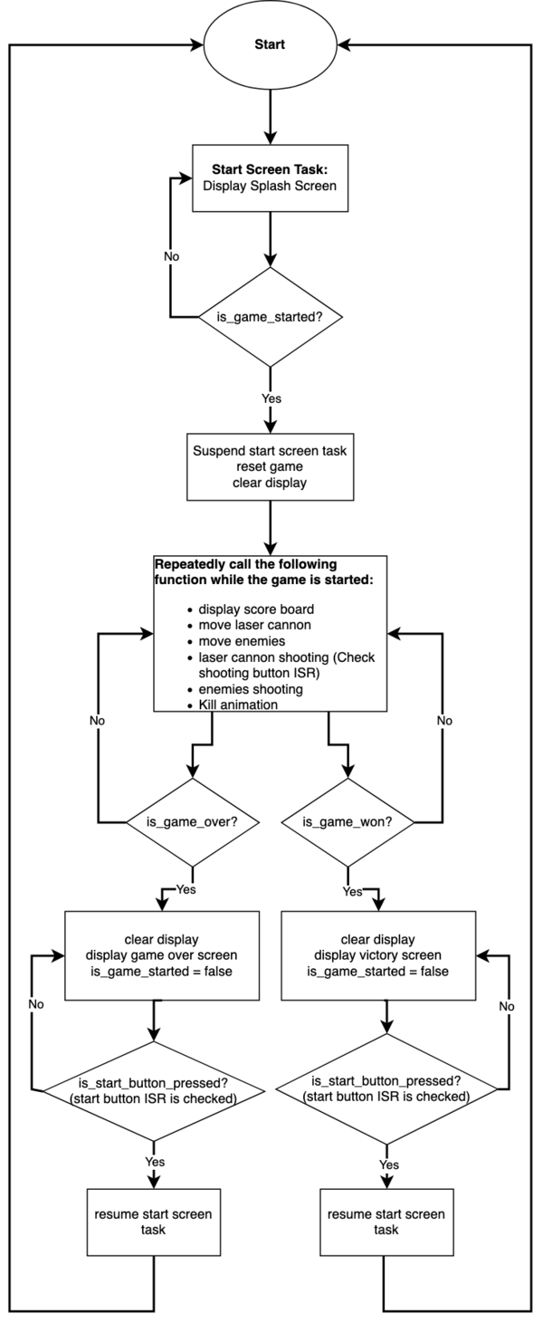
This task continuously displays the splash screen if the game is not started. It also uses a binary semaphore to receive the interrupt when the start button is pressed. When the start button is pressed the game is reset, the display is cleared to move to the next screen and the task is suspended.
Victory Screen Task
This task checks the winning status of the game. If the game is won it clears the display, displays the victory screen, and sets back a boolean variable called is_game_started back to false. It also uses a binary semaphore to receive the interrupt when the start button is pressed. When the start button is pressed the game won status is set back to false and the start screen task is resumed.
Game Over Screen Task
This task checks the game over status of the game. If the game is over it clears the display, displays the game over screen, and sets back is_game_started back to false. It also uses a binary semaphore to receive the interrupt when the start button is pressed. When the start button is pressed the game over status is set back to false and the start screen task is resumed.
Move Laser Cannon Task
This task calls the move laser cannon function only when the game is started. Its only job is to enable the control of the laser cannon through the joystick.
Move Enemies Task
This task calls the move enemies function only when the game is started. Its only job is to move the enemies left to right and down. The logic behind this function involves checking how many enemies are left to determine the correct movement and increase the enemies movement speed.
Laser Cannon Shooting Task
This task updates the bullet location and uses a binary semaphore to receive the interrupt when the shooting button is pressed and call the shoot bullet function. These functions are called only when the game is started.
Enemy Shooting Task
This task calls check valid enemy to shoot bullet function only when the game is started. The logic behind this function involves choosing an enemy that is still alive and it is valid to shoot a bullet to the laser cannon.
Kill Animation Task
This task checks for the status when an enemy has been killed and it needs to show the killing animation. The job of this task is to simply suspend the move enemies task when an enemy has been killed so that for a brief instant all of the enemies are stopped while the killing animation is display and then is resumed again.
Play Game Sound Task (SD Card Reading)
This tasks reads the file specified from the SD card loaded onto the board. The file name is specified by a queue that is received from Which Song to Play Task. The job of thie task is purely to read the SD card contents and send the audio information to the Audio Decoding Task.
Audio Decoder Task
This tasks only purpose is to play the audio data that is received from a queue. The task is the highest priority to ensure that no other task can interrupt it while audio files are sent. This ensures no audible delay in music playback.
Which Song to Play Task
This task receives a UART byte specifying an opcode. The task translate that opcode into a specific song name which is sent to Play Game Sound Task so the song file may be open and read. The UART byte is eent from the game board inside specific game logic calls(not task calls).
Volume Control Task
This task allows the volume of the MP3 Decoder to be adjusted based on what interrupt is received. The two buttons associated with volume up and volume down result in an interrupt. The task will read a semaphore and adjust the volume accordingly.
Game logic high level design
The diagram below showcases the higher level design of the game on the Game Logic board. The diagram will showcase what a user will experience from start screen to end screen(whether its game over or your high score).
3D PRINTED ENCLOSURE
Design
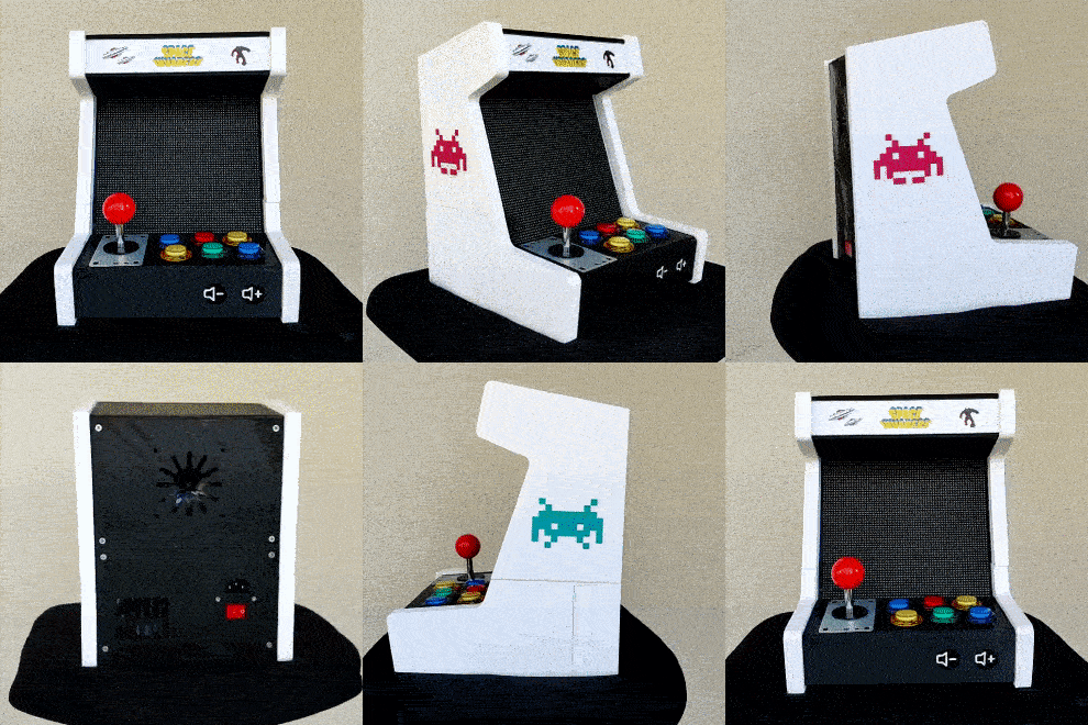
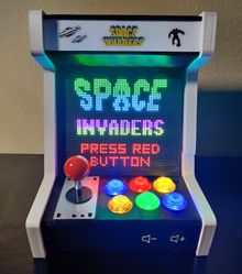
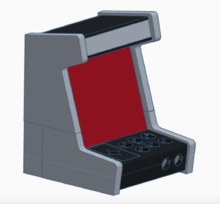
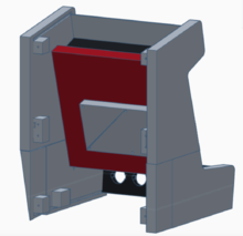
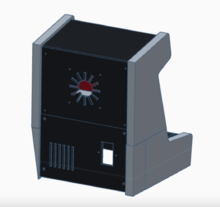
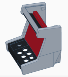
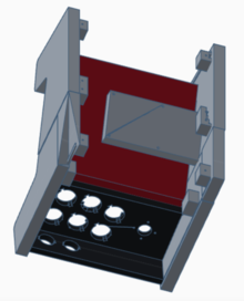
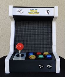
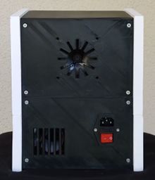
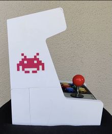
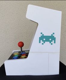
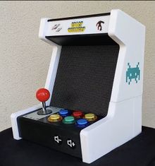
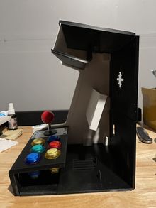
The 3D model design of the arcade cabinet was modified according to our needs to fit the LED matrix display. Credit goes to the designer of the model which can be found on thingiverse at this link. The model took a little over a week to be printed using a 0.2 resolution with 20% infill. The buttons for the volume were custom made with a thickness of 2mm so that touch sensors would detect the input from the user. Show below are pictures of the 3D model as well as the printed result.
3D printed result
TESTING & TECHNICAL CHALLENGES
LED Matrix Displaying Incorrect Colors
While testing the driver it was identified an issue with the LED matrix not displaying the correct colors or at times not displaying them at all in certain parts of the display. To analyze this problem different objects were drawn in different sections of the display to understand the cause of this behavior. While testing it was noticed that the LED matrix would display the correct color only when both the top 32 rows and bottom 32 rows were active or when at least one row was active in both sections. After debugging the code and ensuring that the logic to display the pixels was correct the problem turned to be that the cable that connects to HB75E connector of the LED matrix had a few defective pins which were causing issues on some of the registers that control the RGB colors. After extensively testing by drawing more objects it was deduced that the root cause of this issue was a bad cable.
PCB Design
While testing the ribbon cables, we have identified out that the purchased double row ribbon did not invert pin rows as a normal ribbon cable does.
MP3 Decoder
When initially developing the MP3 Decoder driver, we ran into issues where no sound was being played. After switching to SSP1 (originally was using SSP2 during development), the sound was correctly working. We believe the root of the problem was that the SSP2 pins are also used for the SD card reader and there was a mutex lock occurring that we did not initially anticipate. Another issue occurred when combining the two boards(SJ2 Game Logic and SJ2 MP3 Decoder Board) to play the game play audio, but we encountered an error with the UART queues which was quickly mediated. The two boards are using queue for UART puts and get instead of a polled approach. The final outcome was successful communication between the two boards and no noticeable delay in audio playback.
CONCLUSION
The project was an overall success achieving mostly all of our goals initially outlined during the start of the project. The game was able to properly run and mimic the original Space Invaders game. The LED Matrix, MP3 Decoder, and various joystick controls all functioned correctly during the final demo allowing for a flawless experience of the 1980's game. The LED matrix was capable of loading the various monsters, cannons and bullets all while playing the sounds for each of the game items. The demo showcased that the laser cannon was able to move around and shoot the enemies to gain points, all while losing lives if shot by the enemies. We were able to learn a lot about a real world project such as FreeRTOS applications, drivers, PCB design, power management circuits, git source code management, and final integration testing. This project allowed us to understand the importance of writing down requirements, planning a schedule for development, and communication between all of us. The communication part proved to be important because during the final testing, we needed to understand how each of the parts come together to form the game. The project checked all of our boxes and allowed us to take our Embedded Systems knowledge to a new level.
ACKNOWLEDGEMENT
We would like to express our gratitude to Professor Preetpal Kang for providing valuable insight and knowledge with us and for guiding us through the completion of this project. We would also like to thank Vidhusi Jain(ISA) for her valuable advice code reviews, and constructive feedback. Also a big shout-out to all of our classmates, for the great Slack discussions which provided solutions and necessary feedback.
APPENDIX
Project Source Code
Project Video
References
LED MATRIX
MP3 DECODER
- VS1053 Datasheet
- MAX98357 I2S Amplifier
- CMPE 146 - MP3 Project
GENERAL
