Difference between revisions of "F20: Space Invaders"
Proj user1 (talk | contribs) (→References) |
Proj user1 (talk | contribs) (→BILL OF MATERIALS) |
||
| Line 279: | Line 279: | ||
! scope="row"| 4 | ! scope="row"| 4 | ||
| Capacitive Touch Switch Button Self-Lock Module | | Capacitive Touch Switch Button Self-Lock Module | ||
| − | | [https://www.amazon.com/gp/product/B07X87GX6G/ref=ppx_yo_dt_b_asin_title_o05_s00?ie=UTF8&psc=1 DAOKI | + | | [https://www.amazon.com/gp/product/B07X87GX6G/ref=ppx_yo_dt_b_asin_title_o05_s00?ie=UTF8&psc=1 DAOKI TTP223 Capacitive Touch Switch Button Self-Lock Module] |
| 2 | | 2 | ||
| $7.56 | | $7.56 | ||
| Line 286: | Line 286: | ||
| MP3 Decoder | | MP3 Decoder | ||
| [https://www.adafruit.com/product/1381 Adafruit VS1053 Mp3 Decoder Breakout Board] | | [https://www.adafruit.com/product/1381 Adafruit VS1053 Mp3 Decoder Breakout Board] | ||
| − | | | + | | 2 |
| $24.95 | | $24.95 | ||
|- | |- | ||
| Line 318: | Line 318: | ||
| 1 | | 1 | ||
| $6.58 | | $6.58 | ||
| + | |- | ||
| + | ! scope="row"| 11 | ||
| + | | Mono Amplifier | ||
| + | | [https://www.adafruit.com/product/3006 Adafruit I2S 3W Class D Amplifier Breakout - MAX98357A] | ||
| + | | 2 | ||
| + | | $5.95 | ||
| + | |- | ||
| + | ! scope="row"| 12 | ||
| + | | PCB | ||
| + | | [https://jlcpcb.com/ JLCPCB Set of 5] | ||
| + | | 1 | ||
| + | | 25.60 | ||
|- | |- | ||
|} | |} | ||
Revision as of 19:26, 13 December 2020
Contents
ABSTRACT
Space Invaders is a fixed one person shooter style video game. The player controls a laser cannon by moving it horizontally across the bottom of the screen and firing at the aliens descending toward the cannon from the top of the screen. There are aliens descending towards the cannon and the player's main goal is to defeat an alien and earn points by shooting it with the laser cannon and destroying it. As more aliens are defeated, the aliens' movement speeds up. The alien invasion is declared successful and the game ends when the aliens have successfully reached the bottom. The final score of total kills is projected after the game ends. The mp3 decoder connected to the speaker will play sound effects required.
INTRODUCTION & OBJECTIVES
Show list of your objectives. This section includes the high level details of your project. You can write about the various sensors or peripherals you used to get your project completed.
Team Members
Technical Responsibilities
| Administrative Roles | ||||
|---|---|---|---|---|
|
Salvatore Nicosia & Akash Vachhani | |||
|
Akhil Cherukuri | |||
|
Salvatore Nicosia | |||
|
Salvatore Nicosia & Akhil Cherukuri | |||
|
Akhil Cherukuri | |||
|
Akash Vachhani | |||
|
Salvatore Nicosia | |||
|
Salvatore Nicosia & Akhil Cherukuri | |||
Administrative Responsibilities
| Administrative Roles | ||||
|---|---|---|---|---|
|
Salvatore Nicosia | |||
|
Salvatore Nicosia & Akash Vachhani | |||
|
Salvatore Nicosia & Akash Vachhani | |||
|
Akhil Cherukuri | |||
|
Akhil Cherukuri | |||
SCHEDULE
| Week# | Start Date | End Date | Task | Status |
|---|---|---|---|---|
| 1 |
|
|
|
|
| 2 |
|
|
|
|
| 3 |
|
|
|
|
| 4 |
|
|
|
|
| 5 |
|
|
|
|
| 6 |
|
|
|
|
| 7 |
|
|
|
|
| 8 |
|
|
|
|
| 9 |
|
|
|
|
| 10 |
|
|
|
|
BILL OF MATERIALS
PRINTED CIRCUIT BOARD
Design And Architecture
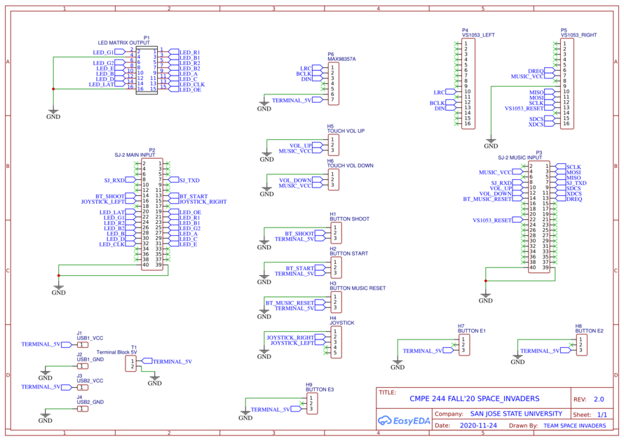
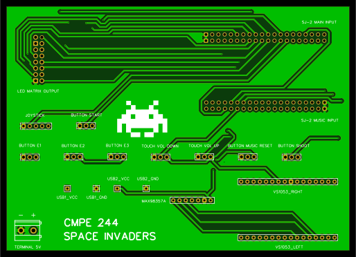
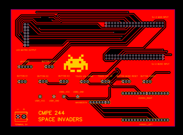
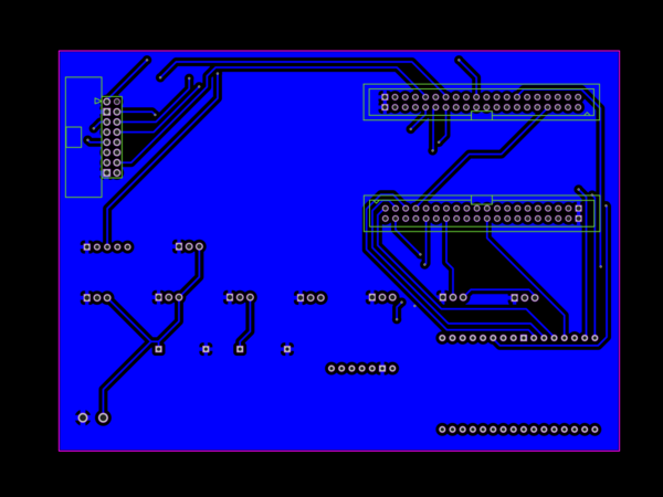
The complete printed circuit board was designed using EasyEDA online software. Implemented both SJ-Two board connectors along with required connections to buttons, led matrix, touch sensors, joystick, VS1053 MP3 Decoder, and MAX98357A I2S Amplifier.
Fabrication
- PCB was sent to fabrication to JLCPCB China which provided PCB with an order of 5 and 2 layers of PCB and common grounded the rest of the copper area.
DRC elements (in mm)
- Track Width = 0.254
- Clearance = 0.152
- Via Diameter = 0.61
- Via Drill Diameter = 0.305
LED MATRIX
Hardware Interface
In this section, you can describe how your hardware communicates, such as which BUSes used. You can discuss your driver implementation here, such that the Software Design section is isolated to talk about high level workings rather than inner working of your project.
LED Matrix Driver
<Discuss here about led matrix driver>
<Discuss here about led matrix hardware>
Software Design
Show your software design. For example, if you are designing an MP3 Player, show the tasks that you are using, and what they are doing at a high level. Do not show the details of the code. For example, do not show exact code, but you may show psuedocode and fragments of code. Keep in mind that you are showing DESIGN of your software, not the inner workings of it.
MP3 DECODER
Hardware Interface
In this section, you can describe how your hardware communicates, such as which BUSes used. You can discuss your driver implementation here, such that the Software Design section is isolated to talk about high level workings rather than inner working of your project.
<Discuss here about MP3 decoder hardware>
MP3 Decoder Driver
<Discuss here about MP3 player driver>
Software Design
Show your software design. For example, if you are designing an MP3 Player, show the tasks that you are using, and what they are doing at a high level. Do not show the details of the code. For example, do not show exact code, but you may show psuedocode and fragments of code. Keep in mind that you are showing DESIGN of your software, not the inner workings of it.
3D PRINTED ENCLOSURE
Design & Implementation
<Discuss here about 3D Printed Enclosure. Attach images of both design and final result>
TESTING & TECHNICAL CHALLENGES
Describe the challenges of your project. What advise would you give yourself or someone else if your project can be started from scratch again? Make a smooth transition to testing section and described what it took to test your project.
Include sub-sections that list out a problem and solution, such as:
LED Matrix Displaying Incorrect Colors
While testing the driver it was identified an issue with the LED matrix not displaying the correct colors or at times not displaying them at all in certain parts of the display. To analyze this problem different objects were drawn in different sections of the display to understand the cause of this behavior. While testing it was noticed that the LED matrix would display the correct color only when both the top 32 rows and bottom 32 rows were active or when at least one row was active in both sections. After debugging the code and ensuring that the logic to display the pixels was correct the problem turned to be that the cable that connects to HB75E connector of the LED matrix had a few defective pins which were causing issues on some of the registers that control the RGB colors. After extensively testing by drawing more objects it was deduced that the root cause of this issue was a bad cable.
<Bug/issue name>
Discuss the issue and resolution.
CONCLUSION
Conclude your project here. You can recap your testing and problems. You should address the "so what" part here to indicate what you ultimately learned from this project. How has this project increased your knowledge?
ACKNOWLEDGEMENT
We would like to express our gratitude to Professor Preetpal Kang for providing valuable insight and knowledge with us and for guiding us through the completion of this project. We would also like to thank Vidhusi Jain(ISA) for her valuable advice code reviews, and constructive feedback. Also a big shout-out to all of our classmates, for the great Slack discussions which provided solutions and necessary feedback.
APPENDIX
Project Source Code
Project Video
References
LED MATRIX
MP3 DECODER
- VS1053 Datasheet
- MAX98357 I2S Amplifier
- CMPE 146 - MP3 Project
GENERAL


