Difference between revisions of "S20: Canster Truck"
Proj user22 (talk | contribs) (→Hardware Design) |
Proj user22 (talk | contribs) (→Project Video) |
||
| Line 1,521: | Line 1,521: | ||
=== Project Video === | === Project Video === | ||
| + | |||
| + | Youtube Video at [https://youtu.be/zkTs8o7nB6k] | ||
=== Project Source Code === | === Project Source Code === | ||
Revision as of 06:51, 23 May 2020
Contents
- 1 Abstract
- 2 Introduction and Objectives
- 3 Team Members and Responsibilities
- 4 Administrative Responsibilities
- 5 Schedule
- 6 Bill Of Materials
- 7 Printed Circuit Board
- 8 CAN Communication
- 9 Motor Controller
- 10 Geological Controller
- 11 Sensor [Bridge and Sensor Controller]
- 12 Bluetooth Module [Bridge and Sensor Controller]
- 13 Driver [Driver and LCD Controller]
- 14 LCD [Driver and LCD Controller]
- 15 Android Application
- 16 Management
- 17 Conclusion
- 18 References
Abstract
The Canster Truck Project is an autonomous RC car with CAN Bus interfaced controllers. The development of the RC car's subsystem modules (Interfacing of Ultrasonic Sensor, LIDAR, Bluetooth, GPS, Compass and CAN modules) was divided among six team members. The aim of the project is to develop an autonomous RC Car which can navigate from one source location to the selected destination on the app by avoiding obstacles in its path using sensors. Waypoints algorithm is used as the path finding technique.
Introduction and Objectives
The project was divided into 7 modules:
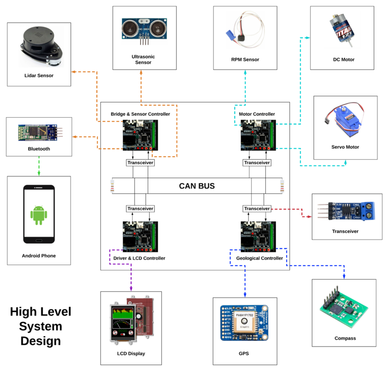
- Bridge and Sensor Controller
- Motor Controller
- Geological Controller
- Driver and LCD Controller
- Hardware Integration
- Android Application
- Testing & Code Review
RC Car Objectives
     1. Driver and LCD Controller - Handles algorithms for obstacle avoidance, route maneuvering, and waypoints
     2. Geological Controller - Recieves coordinates from GPS and Heading from Compass for navigation
     3. Motor Controller - Controls movements of the RC Car
     4. Bridge and Sensor Controller - Detects surrounding objects and interfaces android application to controller via bluetooth
Team Objectives
Team Members and Responsibilities
Gitlab Project Link - Canster Truck
- Niket Naidu LinkedIn Gitlab
- Geological Controller : GPS, Compass, Waypoint Algorithm, Haversine and Bearing Angle logic
- Driver and LCD Controller : GLCD
- Bridge and Sensor Controller : Bluetooth
- Testing & Code Review
- Ganesh Ram Pamadi LinkedIn Gitlab
- Hardware Integration
- Testing & Code Review
- Driver Controller
- Motor Controller
- Nikhil Pabbisetty LinkedIn Gitlab
- Bridge and Sensor Controller
- Motor Controller
- Driver and LCD Controller
- Hardware Integration
Administrative Responsibilities
- Team Lead - Niket Naidu
- Git Repository Manager - Niket Naidu
- Bill Of Materials Manager - Akhil Cherukuri
- Wiki Report Manager - Akhil Cherukuri
Schedule
| Week# | Start Date | End Date | Task | Status |
|---|---|---|---|---|
| 1 | 02/11/2020 | 02/17/2020 |
|
|
| 2 | 02/18/2020 | 02/24/2020 |
|
|
| 3 | 02/25/2020 | 03/02/2020 |
|
|
| 4 | 03/03/2020 | 03/09/2020 |
|
|
| 5 | 03/10/2020 | 03/16/2020 |
|
|
| 6 | 03/17/2020 | 03/23/2020 |
|
|
| 7 | 03/24/2020 | 03/30/2020 |
|
|
| 8 | 03/31/2020 | 04/06/2020 |
|
|
| 9 | 04/07/2020 | 04/13/2020 |
|
|
| 10 | 04/14/2020 | 04/20/2020 |
|
|
| 11 | 04/21/2020 | 04/27/2020 |
|
|
| 12 | 04/28/2020 | 05/04/2020 |
|
|
| 13 | 05/05/2020 | 05/21/2020 |
|
|
Bill Of Materials
| Item# | Part Description | Part Model & Vendor | Quantity | Cost in USD |
|---|---|---|---|---|
| 1 | Microcontroller Boards | SJ2 Boards (Purchased from Preet Kang) | 4 | $200.00 |
| 2 | CAN Transceivers | Waveshare SN65HVD230 | 12 | $54.48 |
| 3 | RC Car | Traxxas 2WD RTR with 2.4Ghz Radio | 1 | $260.00 |
| 4 | Lithium-Ion Battery | Traxxas 7600mAh 2S 7.4V 25C iD LiPo Battery Pack | 1 | $75.00 |
| 5 | Lithium-Ion Battery Charger | Traxxas 2970 EZ-Peak Plus 4-Amp NiMH/LiPo Fast Charger | 1 | $50.00 |
| 6 | Compass Breakout Board | DFRobot CMPS11 Compass | 1 | $29.99 |
| 7 | Bluetooth Breakout Board | DSD TECH Bluetooth HC-05 | 1 | $8.49 |
| 8 | LIDAR Sensor | SEEED STUDIO RPLIDAR A1M8 | 1 | $109.99 |
| 9 | RPM Sensor | Traxxas 6520 RPM Sensor | 1 | $13.70 |
| 10 | GPS Breakout Board | Adafruit Ultimate GPS Breakout v3 | 1 | $44.30 |
| 11 | LCD Display | 4Dsystems 3.2 TFT-LCD ULCD-32PTU | 1 | $79.00 |
| 12 | Ultrasonic Sensors | ELEGOO HC-SR04 Ultrasonic Module | 5 | $12.00 |
| 13 | GPS Antenna | GPS Antenna A1-UX | 1 | $10.98 |
| 14 | PCB Fabrication | JLCPCB | 5 | $40.15 |
| 15 | Miscellaneous | Amazon,Mouser Electronics,Digikey,Anchor Electronics | ~ | $48.07 |
| Total | $1036.15 |
Printed Circuit Board
Design And Architecture
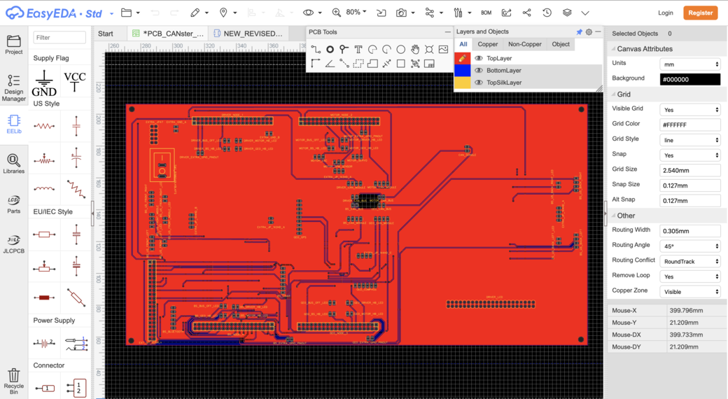
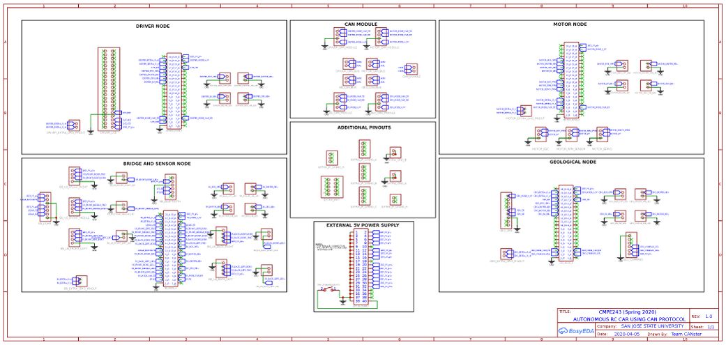
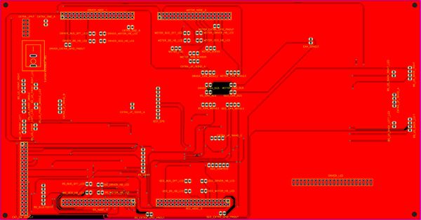
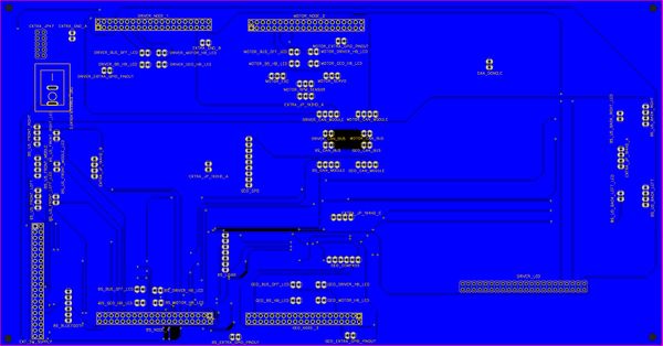
The complete PCB (for boards and hardware peripherals) was designed using EasyEDA online software. The 4 nodes will be communicating via CAN bus and other peripherals are connected to the PCB via headers.
Power Section
We have 2 power banks supplying our system. And the Servo Motor, RPM sensor and DC rear Motor (via ESC) are powered using LiPo battery (6 volts).
- Power bank #1 - Subset 2
- Power bank #2 - Subset 1, Subset 3, Bluetooth Module
NOTE:
Subset 1:
1. LIDAR
2. LCD
3. Compass
Subset 2:
1. Motor node
2. Driver node
3. BS node
Subset 3:
1. Geo node
2. Back ultrasonic sensor
Fabrication
- PCB was sent to fabrication to JLCPCB China which provided PCB with MOQ of 5 and 2 layers of PCB and common grounded the rest of the copper area.
DRC elements (in mils)
- Track Width = 12
- Clearance = 10
- Via Diameter = 24
- Via Drill Diameter = 12
Challenges
- Auto-routing gave lot of challenges (only ~60% success) and sometimes the online server even crashes and faces downtime. Even local routing had lot of issues. So make sure to plan your design accordingly.
- We started our PCB design well ahead of the project. So lot of pre-planning had to be done with regard to final hardware and placement of components in order to avoid spending extra time and money while re-ordering.
- The PCB went through a lot of internal revisions even before placing order. This was time-consuming.
Other hardware challenges:
- Figuring out why various hardware peripherals (GPS, Bluetooth, LIDAR and Ultrasonic sensor) started to malfunction (devices were on but values were either inconsistent / not occurring), took a lot of time to debug. It was due to insufficient power.
CAN Communication
Hardware Design
DBC File
DBC FILE: Gitlab
VERSION ""

NS_:
	BA_
	BA_DEF_
	BA_DEF_DEF_
	BA_DEF_DEF_REL_
	BA_DEF_REL_
	BA_DEF_SGTYPE_
	BA_REL_
	BA_SGTYPE_
	BO_TX_BU_
	BU_BO_REL_
	BU_EV_REL_
	BU_SG_REL_
	CAT_
	CAT_DEF_
	CM_
	ENVVAR_DATA_
	EV_DATA_
	FILTER
	NS_DESC_
	SGTYPE_
	SGTYPE_VAL_
	SG_MUL_VAL_
	SIGTYPE_VALTYPE_
	SIG_GROUP_
	SIG_TYPE_REF_
	SIG_VALTYPE_
	VAL_
	VAL_TABLE_

BS_:

BU_: DBG DRIVER IO MOTOR SENSOR GEO

BO_ 100 DRIVER_HEARTBEAT: 1 DRIVER
 SG_ DRIVER_HEARTBEAT_cmd: 0|8@1+ (1,0) [0|0] "" GEO,MOTOR,SENSOR

BO_ 101 GEO_HEARTBEAT: 1 GEO
 SG_ GEO_HEARTBEAT_cmd: 0|8@1+ (1,0) [0|0] "" DRIVER,MOTOR,SENSOR

BO_ 102 MOTOR_HEARTBEAT: 1 MOTOR
 SG_ MOTOR_HEARTBEAT_cmd: 0|8@1+ (1,0) [0|0] "" DRIVER,GEO,SENSOR

BO_ 103 SENSOR_HEARTBEAT: 1 SENSOR
 SG_ SENSOR_HEARTBEAT_cmd: 0|8@1+ (1,0) [0|0] "" DRIVER,GEO,MOTOR

BO_ 200 MOTOR_STEERING: 1 DRIVER
 SG_ MOTOR_STEERING_direction: 0|8@1- (1,0) [-2|2] "" MOTOR

BO_ 210 DRIVER_COORDINATES: 8 DRIVER
 SG_ DRIVER_COORDINATES_latitude: 0|32@1- (0.000001,-90) [-90|90] "degrees" GEO
 SG_ DRIVER_COORDINATES_longitude: 32|32@1- (0.000001,-180) [-180|180] "degrees" GEO

BO_ 220 MOTOR_SPEED: 1 DRIVER
 SG_ MOTOR_SPEED_processed: 0|8@1- (1,0) [-3|3] "" MOTOR

BO_ 300 GEO_DEGREE: 8 GEO
 SG_ GEO_DEGREE_current: 0|32@1+ (0.000001,0) [0|360] "degrees" DRIVER
 SG_ GEO_DEGREE_required: 32|32@1+ (0.000001,0) [0|360] "degrees" DRIVER

BO_ 310 GEO_DESTINATION_REACHED: 1 GEO
 SG_ GEO_DESTINATION_REACHED_cmd: 0|8@1+ (1,0) [0|0] "" DRIVER

BO_ 400 MOTOR_SPEED_FEEDBACK: 4 MOTOR
 SG_ MOTOR_SPEED_current: 0|32@1+ (0.1,0) [0|60] "kph" DRIVER

BO_ 500 SENSOR_BT_COORDINATES: 8 SENSOR
 SG_ SENSOR_BT_COORDINATES_latitude: 0|32@1- (0.000001,-90) [-90|90] "degrees" GEO
 SG_ SENSOR_BT_COORDINATES_longitude: 32|32@1- (0.000001,-180) [-180|180] "degrees" GEO

BO_ 510 SENSOR_SONARS: 8 SENSOR
 SG_ SENSOR_SONARS_left: 0|21@1+ (0.001,0) [0|0] "cm" DRIVER
 SG_ SENSOR_SONARS_right: 21|21@1+ (0.001,0) [0|0] "cm" DRIVER
 SG_ SENSOR_SONARS_middle: 42|21@1+ (0.001,0) [0|0] "cm" DRIVER

BO_ 520 SENSOR_LIDAR: 8 SENSOR
 SG_ SENSOR_LIDAR_middle: 0|16@1+ (1,0) [0|0] "cm" DRIVER
 SG_ SENSOR_LIDAR_slight_left: 16|16@1+ (1,0) [0|0] "cm" DRIVER
 SG_ SENSOR_LIDAR_slight_right: 32|16@1+ (1,0) [0|0] "cm" DRIVER
 SG_ SENSOR_LIDAR_back: 48|16@1+ (1,0) [0|0] "cm" DRIVER

BO_ 530 MOTOR_KEY: 1 SENSOR
 SG_ MOTOR_KEY_val: 0|8@1+ (1,0) [0|0] "" DRIVER

BO_ 900 GEO_CURRENT_COORDINATES: 8 GEO
 SG_ GEO_CURRENT_COORDINATES_latitude: 0|32@1- (0.000001,-90) [-90|90] "degrees" DBG
 SG_ GEO_CURRENT_COORDINATES_longitude: 32|32@1- (0.000001,-180) [-180|180] "degrees" DBG

BO_ 901 GEO_DISTANCE_FROM_DESTINATION: 4 GEO
 SG_ GEO_distance_from_destination: 0|32@1+ (0.001,0) [0|0] "meters" DBG

BO_ 902 MOTOR_INFO_DBG: 4 MOTOR
 SG_ MOTOR_INFO_DBG_rps: 0|16@1+ (1,0) [0|0] "" DBG
 SG_ MOTOR_INFO_DBG_pwm: 16|16@1+ (0.001,0) [0|0] "" DBG

BO_ 903 LIPO_BATTERY_VOLTAGE_DBG: 4 MOTOR
 SG_ LIPO_BATTERY_VOLTAGE_val: 0|32@1+ (0.01,0) [0|0] "volts" DBG

BO_ 904 CURRENT_CHECKPOINT_DBG: 1 GEO
 SG_ CURRENT_CHECKPOINT_val: 0|8@1+ (1,0) [0|0] "" DBG

CM_ "--BU (Network Node) Information--";
CM_ BU_ DRIVER "The driver controller of the car";
CM_ BU_ GEO "The geo controller of the car";
CM_ BU_ MOTOR "The motor controller of the car";
CM_ BU_ SENSOR "The sensor controller of the car";

CM_ "--BO (Message) Information--";
CM_ BO_ 100 "Driver Sync message used to synchronize the controllers";
CM_ BO_ 101 "Geo Sync message used to synchronize the controllers";
CM_ BO_ 102 "Motor Sync message used to synchronize the controllers";
CM_ BO_ 103 "Sensor Sync message used to synchronize the controllers";

CM_ BO_ 200 "Steering direction values sent by Driver Node to Motor Node";
CM_ BO_ 210 "Driver Destination coordinates sent by Driver Node";
CM_ BO_ 220 "Required motor speed computed from Driver Node to Motor Node";

CM_ BO_ 300 "Current and computer/required degree values sent by Geo Node";
CM_ BO_ 310 "Indicator signal to check if the RC car has reached the destination";

CM_ BO_ 400 "Current motor info (rps and kph) sent as feedback to the Driver Node";

CM_ BO_ 500 "Coordinate BT values (destination coordinates) sent by Sensor Node";
CM_ BO_ 510 "LIDAR - Distance from obstacle detected in each sector";
CM_ BO_ 520 "Ultrasonic Sensor - Distance from obstacle detected by each sensor";
CM_ BO_ 530 "Start/Stop signal from the Bluetooth app";

CM_ BO_ 900 "Destination coordinates for BUSMASTER debugging";
CM_ BO_ 901 "Distance from destination";
CM_ BO_ 902 "Supplied PWM value to the motor and its RPM";
CM_ BO_ 903 "LIPO Battery Voltage";
CM_ BO_ 904 "Current checkpoint of the car";

CM_ "--SG (Signal) Information for Heartbeats--";
CM_ SG_ 100 DRIVER_HEARTBEAT_cmd "Heartbeat command from the driver node";
CM_ SG_ 101 GEO_HEARTBEAT_cmd "Heartbeat command from the geological node";
CM_ SG_ 102 MOTOR_HEARTBEAT_cmd "Heartbeat command from the motor node";
CM_ SG_ 103 SENSOR_HEARTBEAT_cmd "Heartbeat command from the sensor node";

CM_ "--SG (Signal) Information for DRIVER Node--";
CM_ SG_ 200 DRIVER_STEERING_direction "Calculated Driver Steering values (-2,2) for Motor";
CM_ SG_ 210 DRIVER_COORDINATES_latitude "Destination Latitude coordinate";
CM_ SG_ 210 DRIVER_COORDINATES_longitude "Destination Longitude coordinate";
CM_ SG_ 220 MOTOR_SPEED "Calculated Driver speed values (-3,3) for Motor";

CM_ "--SG (Signal) Information for GEO Node--";
CM_ SG_ 300 GEO_DEGREE_current "Current Geo Degree relative to true north";
CM_ SG_ 300 GEO_DEGREE_required "Calculated Geo Degree computed by Haversine Formula";
CM_ SG_ 310 GEO_DESTINATION_REACHED "Indicator signal to check if the RC car has reached the destination";

CM_ "--SG (Signal) Information for MOTOR Node--";
CM_ SG_ 400 MOTOR_SPEED_FEEDBACK "Feedback speed (kph) sent by Motor Node";

CM_ "--SG (Signal) Information for SENSOR Node--";
CM_ SG_ 500 SENSOR_BT_COORDINATES_latitude "Destination Latitude received over Bluetooth";
CM_ SG_ 500 SENSOR_BT_COORDINATES_longitude "Destination Longitude received over Bluetooth";
CM_ SG_ 510 SENSOR_SONARS_left "Ultrasonic Sensor attached to the left side";
CM_ SG_ 510 SENSOR_SONARS_right "Ultrasonic Sensor attached to the right side";
CM_ SG_ 510 SENSOR_SONARS_middle "Ultrasonic Sensor attached to the middle";
CM_ SG_ 510 SENSOR_SONARS_back_left "Ultrasonic Sensor attached to the back left side";
CM_ SG_ 510 SENSOR_SONARS_back_right "Ultrasonic Sensor attached to the back right side";
CM_ SG_ 520 SENSOR_LIDAR_middle "Lidar sensing the middle sector (-15 to 15 degrees)";
CM_ SG_ 520 SENSOR_LIDAR_slight_left "Lidar sensing the slight left sector (-45 to -15 degrees)";
CM_ SG_ 520 SENSOR_LIDAR_slight_right "Lidar sensing the slight right sector (15 to 45 degrees)";
CM_ SG_ 520 SENSOR_LIDAR_back "Lidar sensing the back of the car (165 to 195 degrees)";
CM_ SG_ 530 MOTOR_KEY_val "1 -> Start the motor from the app, 0 -> Stop";

CM_ SG_ 900 GEO_CURRENT_COORDINATES_latitude "Current Latitude";
CM_ SG_ 900 GEO_CURRENT_COORDINATES_longitude "Current Longitude";
CM_ SG_ 901 GEO_distance_from_destination "Distance from destination";
CM_ SG_ 902 MOTOR_INFO_DBG_rps "Current RPS value of the motor";
CM_ SG_ 902 MOTOR_INFO_DBG_pwm "Supplied motor PWM value";
CM_ SG_ 903 LIPO_BATTERY_VOLTAGE_val "LIPO Battery Voltage";
CM_ SG_ 904 CURRENT_CHECKPOINT_val "Current checkpoint of the car";

BA_DEF_ "BusType" STRING ;
BA_DEF_ BO_ "GenMsgCycleTime" INT 0 0;
BA_DEF_ SG_ "FieldType" STRING ;

BA_DEF_DEF_ "BusType" "CAN";
BA_DEF_DEF_ "FieldType" "";
BA_DEF_DEF_ "GenMsgCycleTime" 0;

BA_ "GenMsgCycleTime" BO_ 100 1000;
BA_ "GenMsgCycleTime" BO_ 200 50;
BA_ "FieldType" SG_ 100 DRIVER_HEARTBEAT_cmd "DRIVER_HEARTBEAT_cmd";
BA_ "FieldType" SG_ 102 GEO_HEARTBEAT_cmd "GEO_HEARTBEAT_cmd";
BA_ "FieldType" SG_ 103 MOTOR_HEARTBEAT_cmd "MOTOR_HEARTBEAT_cmd";
BA_ "FieldType" SG_ 104 SENSOR_HEARTBEAT_cmd "SENSOR_HEARTBEAT_cmd";

BA_ "FieldType" SG_ 200 MOTOR_STEERING "MOTOR_STEERING";
BA_ "FieldType" SG_ 230 MOTOR_SPEED_val "MOTOR_SPEED_val";
BA_ "FieldType" SG_ 310 GEO_DESTINATION_REACHED_cmd "GEO_DESTINATION_REACHED_cmd";

VAL_ 100 DRIVER_HEARTBEAT_cmd 2 "DRIVER_HEARTBEAT_cmd_REBOOT" 1 "DRIVER_HEARTBEAT_cmd_SYNC" 0 "DRIVER_HEARTBEAT_cmd_NOOP" ;
VAL_ 101 GEO_HEARTBEAT_cmd 2 "GEO_HEARTBEAT_cmd_REBOOT" 1 "GEO_HEARTBEAT_cmd_SYNC" 0 "GEO_HEARTBEAT_cmd_NOOP";
VAL_ 102 MOTOR_HEARTBEAT_cmd 20 "MOTOR_HEARTBEAT_cmd_REBOOT" 10 "MOTOR_HEARTBEAT_cmd_SYNC" 0 "MOTOR_HEARTBEAT_cmd_NOOP" ;
VAL_ 103 SENSOR_HEARTBEAT_cmd 200 "SENSOR_HEARTBEAT_cmd_REBOOT" 100 "SENSOR_HEARTBEAT_cmd_SYNC" 0 "SENSOR_HEARTBEAT_cmd_NOOP" ;

VAL_ 200 MOTOR_STEERING_direction -2 "MOTOR_STEERING_hard_left" -1 "MOTOR_STEERING_slight_left" 0 "MOTOR_STEERING_straight" 1 "MOTOR_STEERING_slight_right" 2 "MOTOR_STEERING_hard_right";
VAL_ 220 MOTOR_SPEED_processed -3 "MOTOR_SPEED_reverse_fast" -2 "MOTOR_SPEED_reverse_medium" -1 "MOTOR_SPEED_reverse_slow" 0 "MOTOR_SPEED_neutral" 1 "MOTOR_SPEED_forward_slow" 2 "MOTOR_SPEED_forward_medium" 3 "MOTOR_SPEED_forward_fast";
VAL_ 310 GEO_DESTINATION_REACHED_cmd 1 "GEO_DESTINATION_REACHED_cmd_REACHED" 0 "GEO_DESTINATION_REACHED_cmd_NOT_REACHED";
Motor Controller
This controller is used to control the components of the car-related to motor. We can control the speed and steering of the car having interfaced with various components with the SJ-2 board. The servo motor is controlled via PWM and is used to set the steering direction of the car. The DC motor is controlled by the Electronic Speed Controller (ESC) via PWM for speed. We read the speed of the car by using an RPM sensor. By using the RPM sensor values, a feedback loop has been designed to regulate the speed of the car. A state machine has been designed to manage the forward and backward movements of the car. Additionally, a voltage divider circuit has been implemented to read the battery voltage. All motor functionality and CAN message communication is run at 10 Hz.
Hardware Design
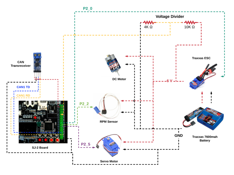
The following diagram details the hardware implementation of the motor module with the SJTwo board: Hardware Interface
Servo Motor
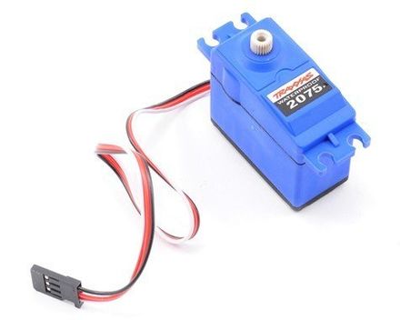
The servo motor responds to PWM pulses. It has three pins namely Vcc, PWM Input Signal, and GND. The servo is powered using 6V from the car battery. Based on the PWM signal supplied from the SJTwo board the front wheels are turned.
| Sr. No. | Wires - Servo Motor | Function |
|---|---|---|
| 1 | PWM Connected to P2.5 | PWM Signal from Sj-2 Board |
| 2 | VCC | 6V supply from ESC |
| 3 | GND | Common Ground |
Electronic Speed Controller (ESC)
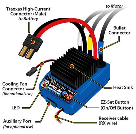
The ESC is used to control the DC motor. It is supplied power using the 7.4 V LiPo battery. It has three pins namely Vout, PWM Input Signal, and GND. Based on the PWM input signal, the speed and forward, neutral, and backward movements of the car is changed. Vout is given to the RPM sensor and Servo motor.
| Sr. No. | Wires - RPM Sensor | Function |
|---|---|---|
| 1 | Signal Wire Connected to P2.0 | GPIO that supplies pulses to controller |
| 2 | VCC | 6V supply from ESC |
| 3 | GND | Common Ground |
DC Motor
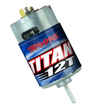
The DC motor is controlled using the ESC. It has two pins, a positive and a negative terminal. A PWM signal wire is connected to the microcontroller and the required current is provided by the LiPo battery and the ESC. The DC motor is controlled using PWM at 10Hz.
|
Note: First calibrate the DC motor or the motor will not respond to your PWM pulses. For help with calibration go to this website
RPM Sensor
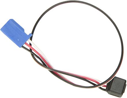
The RPM sensor is used to get the current speed of the car. We use the info for creating a feedback loop (PID) for maintaining the speed of the car in uphill and downhill situations. The RPM sensor mounts on the rear DC motor shaft compartment with a special assembly also provided by Traxxas. The magnet which attached to the inner gear generates a pulse each rotation. The sensor works on the hall effect principle where it provides a current across its terminal when placed in a magnet's field. The RPM sensor has three pins namely Vcc, Signal, and GND.
| Sr. No. | Wires - RPM Sensor | Function |
|---|---|---|
| 1 | Signal Wire Connected to P2.2 | GPIO that supplies pulses to controller |
| 2 | VCC | 6V supply from ESC |
| 3 | GND | Common Ground |
Software Design
The software for the motor node was divided into multiple files and made modular to improve readability and understanding of the complex logic involved. The main code modules are for:
- Servo Motor
- Electronic Speed Controller
- RPM Sensor
- Motor Wrapper
- Battery Voltage
The motor wrapper module is used to wrap all the code from the esc, servo, and rpm modules into simple to use functions to be called in the periodic tasks.
Servo Motor
It uses the steering value sent from the driver (-2 to 2) and matches it to the appropriate PWM value for steering. This code module is run at 10Hz.
void servo__steer_processor(int16_t steering_value) {
  switch (steering_value) {
  case MOTOR_STEERING_hard_left:
    servo__steer_hard_left();
    break;
  case MOTOR_STEERING_slight_left:
    servo__steer_soft_left();
    break;
  case MOTOR_STEERING_straight:
    servo__steer_straight();
    break;
  case MOTOR_STEERING_slight_right:
    servo__steer_soft_right();
    break;
  case MOTOR_STEERING_hard_right:
    servo__steer_hard_right();
    break;
  default:
    printf("\nDid not receive steering value");
  }
}
Electronic Speed Controller
This code module is used to control the DC motor. It receives the motor direction value from the driver and sets the appropriate PWM value. Based on the value the motor is commanded to move the car forward or backwards. A switch case is implemented to set PWM values for movement in different directions along with different speeds.
void esc__direction_processor(int16_t direction_value) {
  desired_direction_value = direction_value;
  switch (direction_value) {
  case MOTOR_SPEED_reverse_fast:
    esc__reverse_fast();
    break;
  case MOTOR_SPEED_reverse_medium:
    esc__reverse_medium();
    break;
  case MOTOR_SPEED_reverse_slow:
    esc__reverse_slow();
    break;
  case MOTOR_SPEED_neutral:
    esc__neutral();
    break;
  case MOTOR_SPEED_forward_slow:
    esc__forward_slow();
    break;
  case MOTOR_SPEED_forward_medium:
    esc__forward_medium();
    break;
  case MOTOR_SPEED_forward_fast:
    esc__forward_fast();
    break;

  default:
    printf("\nDid not receive direction and speed value");
  }
}
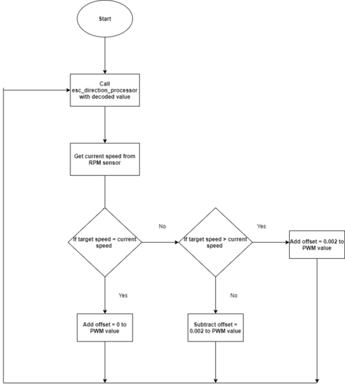
There is also a feedback loop to control the speed. The ESC code depends on the rpm sensor code for the current speed values.
double current_speed = get_speed_kph();
double desired_speed = desired_speed_kph;
float adjusted_duty_cycle = 0.0;
adjusted_duty_cycle = duty_cycle + (speed_to_pwm_adjustment(desired_speed, current_speed));
RPM Sensor
This code module is used to get current speed data from the RPM sensor. It is based on interrupts. When the wheel rotates once, we get one pulse due to the magnet installed. This pulse generates a falling edge interrupt during which we increment the pulse counter. Since, this code is run at 1Hz we collect the number of pulses generated every one second. This gives us the number of rotations per second using which we can calculate the speed in kph.
  float rpm__calculate_speed_kph() {
  uint16_t rotation_per_sec = pulse_count;
  pulse_count = 0;
  speed_kph = ((CIRCUMFERENCE_METER * rotation_per_sec) * (MPS_TO_KPH_CONVERSION_FACTOR)) / GEAR_RATIO;
  return speed_kph;
}
Motor Wrapper
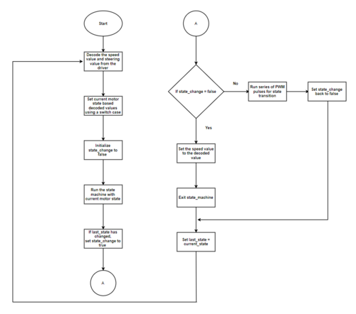
As mentioned above, the main function of this code module is to wrap all the other code modules and call the right functions at the appropriate frequency. The motor wrapper code also includes a state machine for ensuring a smooth transition between forward to backward state and vice versa. In order to achieve a smooth transition, a series of PWM pulses must be generated at the right time. For example, when the motor is moving from forward to backward state, a reverse value must be given first followed by at least three neutral values, and then continue with reverse values.
LiPo Battery Voltage
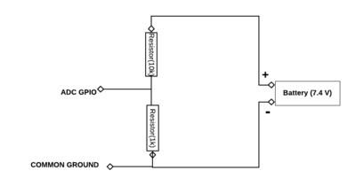
The LiPo Battery Voltage was calculated using ADC in Burst Mode. A LiPo Hardware module was created for the same which contained two functions, lipo__init and lipo__get_voltage.
The voltage divider circuit is stepped down from 7.4V to 2.1V using 10K and 4K Resistor pair.
LiPo Initialization
The LiPo Initialization phase initializes the ADC, Enables Burst mode on the ADC pins and configures the Alternate Function Registers for the same.
Getting LiPo Voltage
We read the raw ADC value from the LPC Hardware register. This value will be from 0 - 3.3V. However due to our voltage divider configuration the max voltage that we should theoretically get is 2.1V. This means that 2.1V corresponds to 7.4V of the LIPO Battery voltage.
The formula used is
(raw_adc_value * MAX_LIPO_BATTERY_VOLTAGE_VALUE) / MAX_LIPO_ADC_VALUE
Technical Challenges
Solution: The motor requires a series of PWM pulses which is specific to the car to transition from forward mode to reverse mode. In our case we had to give the PWM pulses in the following sequence. Suppose,
- Forward (16) (callback_count = 0)
- Forward (16) (callback_count = 1)
- Reverse (14) (callback_count = 2)
- Neutral (15) (callback_count = 3)
- Neutral (15) (callback_count = 4)
- Neutral (15) (callback_count = 5)
- Reverse (14) (callback_count = 6)
- Continue reverse
Similarly, the reverse to forward can also be implemented.
Solution: Connect the voltage divider circuit to the common ground rather than taking the ground from the ESC.
Geological Controller
Messages
- GEO_HEARTBEAT: Used to check for MIA by other nodes. Highest priority message for GEO Node
- GEO_DEGREE: Sends the current degree relative to the North Pole computed by the Compass and the Required degree relative to the North Pole computed by Bearing Angle using the Current Coordinate and Destination Coordinate.
- GEO_DESTINATION_REACHED: Sets a flag, 0 for destination not reached and 1 for destination reached
- GEO_CURRENT_COORDINATES: Debug Message used to send the Current GPS Coordinates
- GEO_DISTANCE_FROM_DESTINATION: Debug message used to send the Distance from Destination
- CURRENT_CHECKPOINT_DBG: Debug message used to check which checkpoint is being navigated to
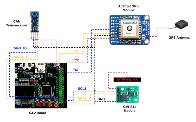
Hardware Design
Software Design
Overview
- Inside the `periodic_callback__initialize`
- Initialize the CAN BUS
- Initialize the GPS
- Inside the `periodic_callback__1hz`
- Handle all MIA (from other Nodes)
- Update GPS LED when init and in case of failure
- Compute the GEO logic for Waypoints algorithm once every second (1000 ms)
- Inside the `periodic_callback__10hz`
- Handle CAN Incoming messages (Decode)
- Transmit CAN Geo messages (Encode and send)
- Compute the GPS Coordinate
Compass I2C Driver
An online datasheet resource was used to work with the Compass (CMPS11 Datasheet) Initially the Compass I2C Driver was tested using the Terminal I2C Helper built by our Professor Preetpal Kang. Using this resource we were quickly able to read various I2C Registers and display it onto the terminal.
For our project the only required part of the Compass was the 16-bit Compass Bearing value (0-3599) i.e 0-359.9 degree values. These values were stored in the 2nd and 3rd register (Register 2 being the High Byte). Once the raw data was received over I2C we could easily combine the data
uint16_t  bearing_value = (Reg2 << 8) | Reg3;
float rval = bearing_value / 10.0;
return rval;
The returned value were transmitted to the Driver Node to compute its steering based on the required Bearing Angle.
GPS Initialization
GPS Initialization activates the Hardware GPIO (RX and TX), FreeRTOS Queue for UART Interrupts (UART Module) and Line Buffer Module to parse each GPS line.
GPS Data Parsing
The GPS Hardware module transmits an NMEA string over UART to the SJTwo Board. We read each character one by one and add it to the Line Buffer module. Inside its computation loop, the Line Buffer module checks if a newline character has been received. When a newline character has been received the entire string is extracted from the line buffer module and parsed according to its identifier ($GPRMC, $GPGGA) received and parsed into individual tokens. For our purposes the $GPRMC NMEA string was the most appropriate and it helped us extract the Current Latitude Longitude as well as the Valid/Invalid tag for the Canster Truck.
GPS LED Indication for debugging
A simple module that checks for the GPRMC GPS Message and extracts the A or V valid (Tag). If $GPRMC NMEA string is valid, LED is set, else LED is reset. This gives us onsite debugging capabilities to know if GPS has locked onto a satellite signal.
GEO Logic Module Computation
The GEO Logic Module computes the Bearing Angle, Haversine Distance as well as the Waypoints algorithm.
Bearing Angle:
θ = atan2( sin Δλ ⋅ cos φ2 , cos φ1 ⋅ sin φ2 − sin φ1 ⋅ cos φ2 ⋅ cos Δλ )
where φ1,λ1 is the start point, φ2,λ2 the endpoint (Δλ is the difference in longitude)
Since atan2 returns values in the range -π ... +π (that is, -180° ... +180°), to normalize the result to a compass bearing (in the range 0° ... 360°, with −ve values transformed into the range 180° ... 360°), convert to degrees and then use (θ+360) % 360, where % is (floating point) modulo. For final bearing, simply take the initial bearing from the endpoint to the start point and reverse it (using θ = (θ+180) % 360).
The above article reference gives us the required bearing angle that our car must align itself to, to reach a particular destination coordinate from its current coordinate. The Steering of the vehicle depends on the above-computed angle values.
Haversine Distance Formula:
This uses the ‘haversine’ formula to calculate the great-circle distance between two points – that is, the shortest distance over the earth’s surface – giving an ‘as-the-crow-flies’ distance between the points (ignoring any hills they fly over, of course!).
a = sin²(Δφ/2) + cos φ1 ⋅ cos φ2 ⋅ sin²(Δλ/2)
c = 2 ⋅ atan2( √a, √(1−a) )
d = R ⋅ c
where φ is latitude, λ is longitude, R is earth’s radius (mean radius = 6,371km); note that angles need to be in radians to pass to trig functions!
The above formula is used to calculate the distance between the source coordinate (received via GPS) and the destination coordinate. Later this was used to compute the distance between source coordinate and each individual checkpoint to traverse the shortest distance.
Waypoints Algorithm:
The Waypoints algorithm that was chosen was a slightly modified version of Djikstra’s Algorithm. 3 values were calculated before the final computation
- Distance between source and final destination (DISTsd)
- Distance between source and each individual checkpoint (DISTsc)
- Distance between each individual checkpoint and the final destination. (DISTcd)
If DISTsd was lesser than DISTcd, this checkpoint was discarded (we continue in the loop). Since we would be moving in the opposite direction, rather than towards the final destination.
If DISTsd was greater than DISTcd, then we checked the nearest checkpoint to the source. The minimum value was set initial that was equal to DISTsd.
If DISTsc was lesser than the minimum value stored, DISTsc would become the new minimum value, and the checkpoint index and coordinates would be appropriately stored and returned from the function.
In this way we would navigate to the nearest checkpoint from the source, while also making sure NOT to travel in the opposite direction. This logic is recomputed only when we reach the checkpoint selected and the algorithm runs again to find the next checkpoint that we need to navigate to.
CAN Decode Destination Coordinates
Destination Coordinates are received from the Bridge and Sensor Node and transmitted over the CAN Bus. The value is decoded and stored in the GEO Logic Module. This is a very important value since our entire GEO Logic calculations are based on the Destination Coordinate.
CAN Encode and Send
The main messages that were transmitter are
- Geo Degree
- Geo Destination Reached
- Distance from Destination Debug and Checkpoint Index debug
Geo Degree Computation as per Waypoints Algorithm:
Geo Degree was computed as per the current coordinates and the most recently computed checkpoint coordinates. This bearing angle calculation w.r.t computed checkpoint would continue till we do not reach that particular checkpoint. Once we reach the computed checkpoint, Waypoint algorithm is recomputed as per the process mentioned above and the algorithm runs again.
Geo Destination Reached:
An Area of around 4 meters was set around the destination coordinate to check if the destination had been reached. This measurement was taken into consideration to allow for the loss in precision when transmitting data over CAN as well as any irregularities that might occur when getting values from the GPS. Having an area of 4 meters was very accurate for all of our test runs.
Geo Distance from Destination Debug and Checkpoint Index Debug:
Getting debug information was very critical to speed up our development process. In this case we could actively see if our algorithm worked properly. The Geo Distance from Destination was used to see if we were moving closer to our destination or veering further away from it. The Checkpoint Index was used to see which checkpoint index we were traveling to. By knowing the placements of the Individual checkpoints we could manually as well as programmatically (via Android application) verify the working of our Canster Truck.
Technical Challenges
- DBC Challenge for GEO Coordinates -> Could not encode more than 5-6 decimal places at a time, on later investigation we found that the 10000 is an int value, however 100000 overflows the int value.
- Creating an efficient algorithm for Waypoints, O(n) complexity.
- Getting appropriate fixes for GPS when not in a completely open space.
- GPS used to fluctuate or stop giving values when Battery voltage went below a particular threshold. Always supply 3.3V constantly at a good amperage.
Sensor [Bridge and Sensor Controller]
Ultrasonic Sensor
Hardware Design
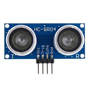
This sensor uses an ultrasonic beam to measure the distances. Based on the time taken between when the beam is sent and received back to the sensor, the distance is calculated in the node. Apart from 5v and GND, this sensor has 2 pins ECHO and TRIG which are interfaced with the SJ-Two board via GPIO.
Software Design
- Init the GPIO pin connected to TRIG of the sensor as output and for ECHO as an input port.
- Attach the interrupt on the ECHO input port.
- Store the system_clock_count before setting the trigger pulse and then set the pulse. Also keep monitoring the input port.
- Take the system_clock_count at the instant of receiving the interrupt.
Distance = (system_clock_count_at_trig - system_clock_count_after_at_echo) / 57.14
Lidar Sensor
Hardware Design
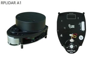
The RPLidar sensor can be powered from a 5v source and uses UART communication to receive commands and transmit data. It has seven pins to interface with. Two sets of the pins (four total) are for power and ground. The remaining three are for UART receive and transmit, and for making the lidar’s motor spin.
Software Design
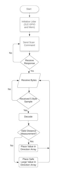
In terms of the lidar, the SJ2 initializes GPIO, UART, and memory for storing the measurement values. After initialization, the command to begin scanning is sent. Here, we wait for the lidar to send a response packet, letting the host (SJ2 board) know it received the command. The response packet the lidar sends will be 7 bytes. If the correct 7 bytes are not received, the command will be sent again.
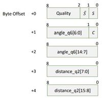
Following the response packet, the lidar begins sending 5-byte measurement data. Each sample contains a distance measurement (in millimeters) and the angle (with respect to the lidar) in which it was taken. The data packet structure is shown in the following figure. In addition to containing the distance and angle, the packet includes a quality value, to indicate the reliability of the measurement, and three check bits (S, ~S, and C). As the data is received via UART, we wait until we have 5 bytes before continuing to process. Before processing the 5 bytes after receiving them, the check bits are confirmed to be correct. If they are incorrect, it will not be processed and we will wait for another sample to be received.
In the case the sample is correct, each measurement value that is in a direction of interest will be placed in an array designated to one of four directions (left, right, front, rear). Each of these directions have their own sector in the lidar’s 360-degree view.
- Right sector: 11° - 30°
- Rear sector: 170° - 190°
- Left sector: 330° - 349°
- Front sector: 350° - 370° (or 10°)
The arrays mentioned will hold roughly 20 measurements, which are every degree in the sector. In the event, objects are too far to measure, the lidar will report 0 mm. distance. Since there is no measurable obstacle, a “large” distance value of 3000 mm. is placed in the array. The smallest distance value will be taken from each array and reported to the driver node for obstacle avoidance.
Technical Challenges
Ultrasonic Sensor
- Power issue The pulses were getting triggered incorrectly and it took a while to figure out that it was due to insufficient power.
LIDAR
- Datasheet not 100% clear: The correct datasheet for the was a bit difficult to obtain, and the manufacturer needed to be contacted. The first document found online was high level and general information about the sensor, but the manufacturer did provide another document that contained the information of the commands and responses to and from the lidar, and their packet structure. The documents did not clearly state the angles with respect to the lidar are fixed, which left me wondering if the lidar will think the direction it is facing when powered on will become the new “zeroth” angle.
- UART Buffer Overflow: When first interfacing with the sensor, the incoming bytes of the lidar were printed on to the terminal to make sure there was a response and to make sense of the information. Since the command we sent results in 5 bytes of data per measurement samples from the lidar and the lidar measured 2000 times per second, there are will be roughly 10k Bytes per second of data incoming that need to be handled continuously. With an improperly sized UART buffer and print statements it is guaranteed to occur, making the lidar data look like random values.
- Proper Parsing of Measurement Data: After sending a command to the lidar, the sensor will send a response packet, followed by the measurement data. The initial response from the lidar is a 7-byte packet, followed by continuous 5-byte measurement samples. I needed to make sure however I handled the response would be independent of how the measurement is handled, so as not to create a potential unwanted offset when receiving measurements.
- Object Detection with Received Data: Once proper communication was set up with the lidar and measurement data was getting decoded, there needed to be a way to measure when obstacles were present. If ~360 measurements are handled entirely independently from one another, it could become a complex and confusing code. To achieve a simple approach, four sectors about 20 degrees in size were used to represent the front, left, right, and rear directions.
- Bugs in Code: When first implementing the code, there were a few bugs from typos, incorrect numbers, and some faulty logic that were found with the use of unit testing. Unit testing helped find these issues and verified the logic was correct, and I would say gave me 90% confidence in my lidar handling.
Bluetooth Module [Bridge and Sensor Controller]
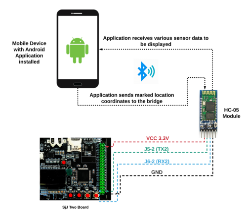
Bridge functionality of the Bridge and Sensor Controller is to establish wireless communication between the SJ-2 Board and the android mobile device using the HC-05 Bluetooth module. The Bridge controller will be receiving start command with destination GEO coordinates and stop command. The Bridge controller will be transmitting the required sensor data and debug information to be displayed on the android application.
Software Design
Low-Level Layer
In this layer, similar to the GPS the UART GPIO was initialized (RX, TX), FreeRTOS Queue was initialized for UART Interrupts and the line buffer module was initialized to parse strings.
Two basic functions bt__read and bt__write were implemented.
As the name suggested, bt__write took a string as its input parameter and transmitted that data to the Android application. bt__read stored the incoming characters into the line buffer, parsed the line received into its identifier and tokens, and invoked a callback function.
Since this was a low-level layer the User would not be directly invoking this library. Instead a Bluetooth Wrapper module was created which would be invoked and used by the user.
Application Layer
The Bluetooth Wrapper module had the appropriate read_once and write_once functions.
The read_once function internally just called the bt__read function. All of the decodings was done inside the Callback Function.
To get the Destination coordinate the string received from the Android Application was in the form of
$loc,<destination_latitude>,<destination_longitude>.
Upon receiving this data we parsed the destination_latitude and destination_longitude, which could later be accessed using getters.
We also set a start flag to notify the Driver Node that destination has been received and we can start steering towards our checkpoints.
Another command implemented was the stop command.
$stop
This was used to send a stop flag to the Driver node.
The write_once function used the getter methods from each CAN Decode message and update its internal state variables. A CSV String was created using the $canster identifier and various debugging points were appended to this message using a comma.
On the Android application side this CSV string was tokenized and displayed onto the Application Debug screen appropriately.
Technical Challenges
Bluetooth peripheral not turning on
- We initially connected the Bluetooth module directly to the SJ-Two board with (Vcc = 3.3v). But it was not giving only 2.7v and hence the device did not turn on.
- We had to connect it to external power source to make it function without hassles.
Driver [Driver and LCD Controller]
Software Design
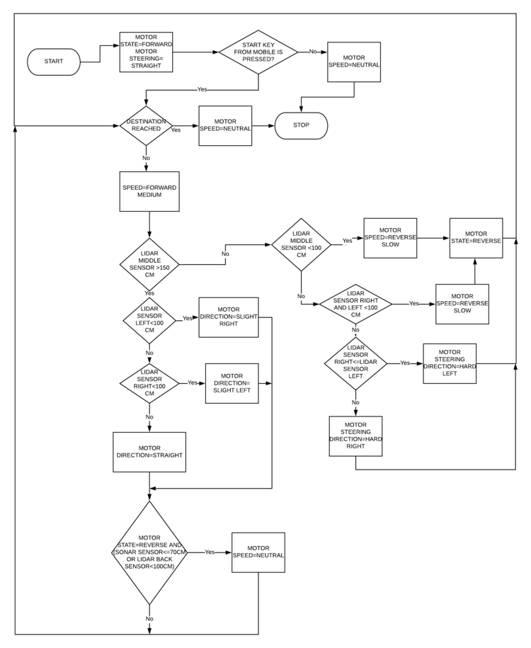
The above block diagram explains the process flow of obstacle detection for the car. The LIDAR detects the obstacle and depending on the distance of obstacle the car takes a slight right and slight left or a hard right and hard left. The state of the car also depends on the value of the LIDAR and ultrasonic sensor. The loose ends of the LIDAR for the reverse condition are checked by the ultrasonic sensors. The The ultrasonic sensor works on the principle of trigger and echo and can detect the obstacles very close by. The range of the Ultrasonic sensor is lower than the LIDAR. Finally, if no obstacle is detected the car goes straight until the destination is reached. The speed of the car is also various when an obstacle is detected to avoid the crash and the car’s smooth transition from one state to another. The key to the android application controls the start and stop the process of the car. If the key is not pressed, then the stays in the
neutral state. The speed of the car is controlled by the changing duty cycle of the input voltage. There are seven-speed levels in which the motor can run on. These speed levels are Forward Slow, Medium, Fast, Reverse Slow, Medium, Fast, and Neutral. The Neutral is the stop condition with a 0% duty cycle.
Technical Challenges
Technical Challenges faced during obstacle detection:
- Due to dimensions of the car and for the perfect obstacle avoidance the values of 100cm and 150cm had to be selected for the turning radius. Hence, it is very important to calibrate these values appropriately, as these values will be unique for different car designs.
- For a situation, where even if the lidar doesn’t detect any obstacle at the middle, the car must take a slight right or a slight left as per our design. This is the case where the obstacle can be a moving one and that is why the lidar middle couldn’t detect it.
LCD [Driver and LCD Controller]
Hardware Design
Software Design
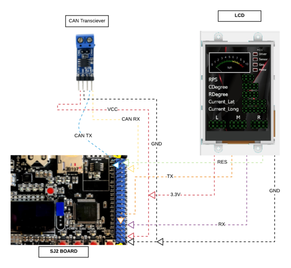
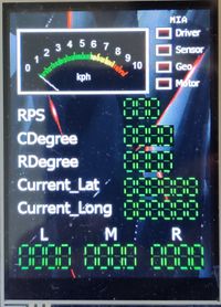
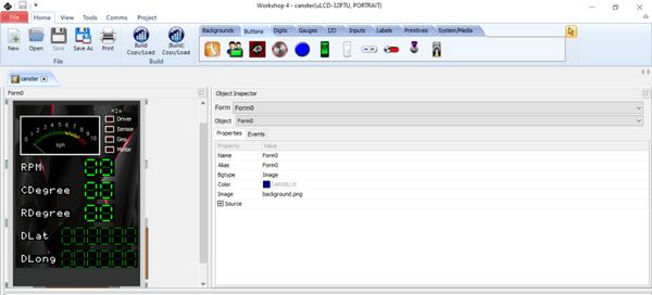
The GLCD used was created by 4DSystems, using their IDE a UI was created. Each UI component could be controlled by sending UART data targeted at the widget address. The best part about this GLCD was that we had a lot of interactive widgets to display debugging information in real-time. The GLCD code was divided into 3 parts:
Low-Level Initialization
Initialize the low-level hardware interfaces to send and receive data from the GLCD. Similar to the GPS and Bluetooth, The UART GPIO was initialized (RX, TX), FreeRTOS Queue was initialized for UART Interrupt and line buffer was used to get a stream of data for parsing.
Low-level read and write commands were used as per the working of the GLCD Module. When Reading data pertaining to a widget on the GLCD we would need to send a particular response packet.
void lcd__read(lcd_object_e object_id, uint8_t object_index, uint8_t *response, uint16_t *response_data) {

  uint8_t checksum = READ_OBJ ^ object_id ^ object_index;
  uint8_t buffer[] = {READ_OBJ, object_id, object_index, checksum};

  lcd__write_data(buffer, sizeof(buffer) / sizeof(uint8_t));
  lcd__read_response_id(response);
  lcd__read_response_data(response_data);
}
The response_data returned contains the Widget ID as well as the current value stored on that widget.
When Writing data pertaining to a widget on a GLCD the process is similar to the above mentioned code.
void lcd__write(lcd_object_e object_id, uint8_t object_index, uint8_t msb, uint8_t lsb, uint8_t *response) {
  uint8_t checksum = WRITE_OBJ ^ object_id ^ object_index ^ msb ^ lsb;
  uint8_t buffer[] = {WRITE_OBJ, object_id, object_index, msb, lsb, checksum};

  lcd__write_data(buffer, sizeof(buffer) / sizeof(uint8_t));
  lcd__read_response_id(response);
}
However in this case we receive only an ACK or NACK from the system. ACK would mean that the write to GLCD widget was successful and the widget now stored appropriate values. NACK would mean that a particular error has occurred. The errors could be regarding baud rate, incorrect bit format, incorrect index values, etc.
GLCD Wrapper for Widgets
The above low-level code had generic read and write functions. However for our UI we were only using 3 Widgets. All of which had different Indexes and Widget IDs. Therefore a very simple library was created to easily interface with those widgets
bool lcd_wrapper__read_led(uint8_t index);
uint16_t lcd_wrapper__read_meter(uint8_t index);
uint16_t lcd_wrapper__read_leddigit(uint8_t index);

bool lcd_wrapper__write_led(uint8_t index, bool value);
bool lcd_wrapper__write_meter(uint8_t index, uint16_t value);
bool lcd_wrapper__write_leddigit(uint8_t index, uint16_t value);
The above code is self-explanatory read and write functions for LED, METER, and LED DIGIT.
GLCD UI
Now that we had our low level and Widget wrapper working properly, we wanted to create our Dynamic UI as well. The code would need to be robust enough to handle any UI that we create on the GLCD which could be reflected equivalently in our C Code.
static void lcd_ui__update_ui(void) {

  lcd_wrapper__write_led(LCD_LED_DRIVER_MIA_INDEX, driver_mia_led);
  lcd_wrapper__write_led(LCD_LED_SENSOR_MIA_INDEX, sensor_mia_led);
  lcd_wrapper__write_led(LCD_LED_GEO_MIA_INDEX, geo_mia_led);
  lcd_wrapper__write_led(LCD_LED_MOTOR_MIA_INDEX, motor_mia_led);

  // kph is always in the range of 0 - 10
  lcd_wrapper__write_meter(LCD_METER_KPH_INDEX, kph_meter % 11);

  // These will be in the Range of 0-99
  lcd_wrapper__write_leddigit(LCD_LEDDIGIT_RPM_INDEX, rpm_leddigit % 100);
  lcd_wrapper__write_leddigit(LCD_LEDDIGIT_CURRENTDEGREE_INDEX, cdegree_leddigit % 100);
  lcd_wrapper__write_leddigit(LCD_LEDDIGIT_REQUIREDDEGREE_INDEX, rdegree_leddigit % 100);
}
As we can see the lcd_ui__update_ui function was called periodically inside the 1Hz function. It updated the screen in real time based on the static values that were stored AND updated inside the LCD UI module.
The Constant INDEX values stored were directly mapped onto the Index values were received from the 4DWorkshop UI Software.
Technical Challenges
- The GLCD needs to be supplied appropriate voltage (5V) at 1A for it to work properly. The LCD does not turn on without an appropriate power supply
- The GLCD UART interface has an additional RES signal. This RES signal resets the GLCD when pulled low. When connecting the UART display it is recommended to always reset the GLCD display for proper working
- The GLCD has a latency of up to 30ms when querying and receiving data. In our case, the real-time system has hard caps on time (i.e up to 1second of delay is possible on the 1Hz function)
- This was rectified by putting the read functions (if any) inside the low priority 1Hz periodic_callback function.
- Write operations do not suffer from such a latency issue since they only send one byte (ACK or NACK) signal back.
- Fortunately most of our logic involved just a write (setting a value on the GLCD) rather than reading or querying the widget.
Android Application
Software Design
The application consists of a total of 5 Activities:
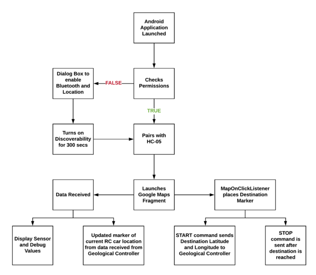
Main Activity
- This is the app launch display screen
- It will check for all the required permission onStart().
- Has search button for connecting from a paired device list view
- Once device is clicked, an intent will start the Map Activity
Map Activity
- For this requirement we are using the Google Maps Fragment, for the map fragment to function we must request an API key from Google and set the key in the manifest of the application.
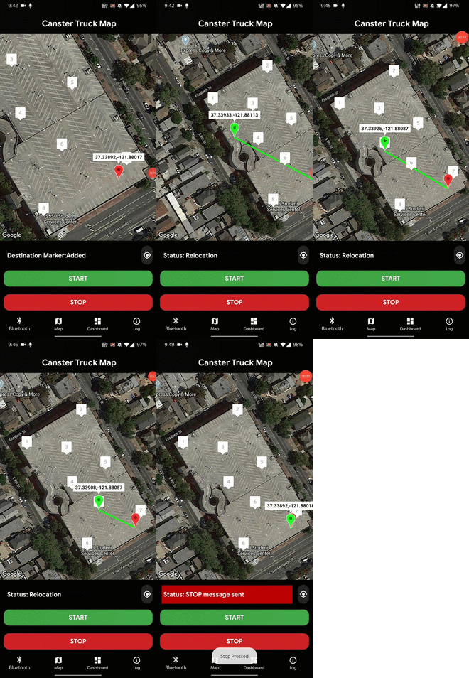
- Destination marker(Red Marker) is set using
setOnMapClickListenerto which the car will navigate to, the destination can be changed by clicking elsewhere on the Map Fragment. The marker can be removed usingsetOnMarkerClickListener. - When the start button is pressed, the start command identifier along with destination latitude and longitude is sent to the car via the write thread. A background thread is started along with it to indicate the current car's position(Green Marker) along with a plotline between the current position and destination.
- When the stop button is pressed, the stop command identifier is sent to the car, to stop and turn off the car.
Info Activity
- Messages from Geological, Driver, Motor coming from CAN bus are decoded by the Sensor and Bridge controller and sent to the Android application as a string.
- The received string is parsed and categorizes the data to store it in the required textView to be displayed.
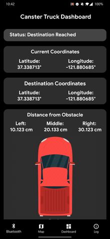
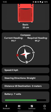
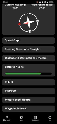
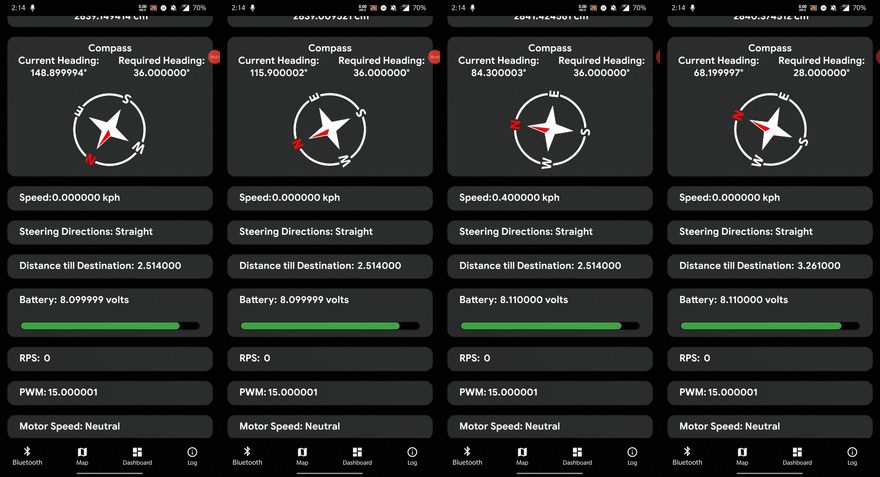
- Bluetooth status, Lidar Values, Ultrasonic Sensor Values, Motor Speed, Motor RPM, Motor PWM, Cars' current location, Compass Heading, Distance till Destination, Checkpoint Index is displayed. This was useful for debugging purposes and allowed us to avoid scanning the mounted LCD or CAN Busmaster on PC during drives.
Debug Activity
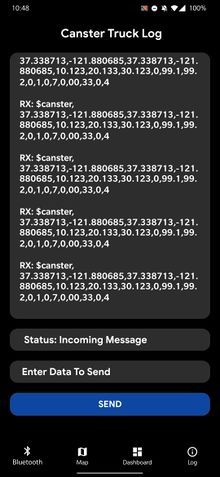
- The main function of this activity is to check all RAW RX and RAW TX messages and create a log of all the data received and sent.
Bluetooth Connection Service Activity
- This is the background activity that handles all the threads required for transmission and receiving data using Bluetooth connections. It has 3 running threads which is called inside other activities using a handler:
- Accept Thread - Listens to BluetoothServerSocket using listenUsingRfcommWithServiceRecord. In order for the RF communication socket to connect to the HC-05, we used the following
UUID: 00001101-0000-1000-8000-00805F9B34FB. This is a generic SSP Bluetooth UUID that enables the socket to directly connected to HC-05 and maintain the connection. - Connect Thread - Creates a Bluetooth socket using createRfcommSocketToServiceRecord
- Connected Thread - Creates socket.getInputStream(); and socket.getOutputStream(); when bytes are available in input stream it will read them into a buffer.
- All messages for activities are done by
Handler mHandler.obtainMessage(); mHandler.sendMessage();
- All messages for activities are done by
Receieved string:
- A String is sent to the Bluetooth app from HC-05 and when it receives a string with identifier "$canster", the message is prased accordingly by using the string delimiter ',' and is ended by the newline character '\n' which will remove the data from StringBuffer.
-
Example: $canster,37.339334,-121.881123,37.338713,-121.880685,10.123,20.133,30.123,10.5,88.1,99.2,-2,1,44,7,11,22,33,-3,23\n
Manifest:
    <uses-permission android:name="android.permission.ACCESS_FINE_LOCATION" />
    <uses-permission android:name="android.permission.BLUETOOTH" />
    <uses-permission android:name="android.permission.BLUETOOTH_ADMIN" />
    <uses-permission android:name="android.permission.ACCESS_COARSE_LOCATION" />
    <uses-permission android:name="android.permission.ACCESS_NETWORK_STATE" />
    <uses-permission android:name="android.permission.INTERNET" />
Dependencies:
    implementation fileTree(dir: 'libs', include: ['*.jar'])
    implementation 'com.google.android.gms:play-services-maps:17.0.0'
    compile 'com.google.maps.android:android-maps-utils:0.4+'
    implementation 'androidx.cardview:cardview:1.0.0'
    implementation 'com.google.android.gms:play-services-location:17.0.0'
    implementation 'androidx.appcompat:appcompat:1.1.0'
    implementation 'androidx.constraintlayout:constraintlayout:1.1.3'
    implementation 'com.android.support:design:28.0.0'
    implementation 'androidx.navigation:navigation-fragment:2.2.1'
    implementation 'androidx.navigation:navigation-ui:2.2.1'
    implementation 'androidx.lifecycle:lifecycle-extensions:2.2.0'
Technical Challenges
- Bluetooth Discovery: While creating the android application, we were not able to see any Bluetooth devices in the paired device list. The problem was that for the Android versions above Lillipop we would also need location access. We have solved it by writing a function to check whether to check for permissions or not.
private void checkBluetoothPermissions() {
        Log.d(TAG, "checkBTPermissions: Checking permissions");
        int permission_check = this.checkSelfPermission("Manifest.permission.ACCESS_FINE_LOCATION");
        permission_check += this.checkSelfPermission("Manifest.permission.ACCESS_COARSE_LOCATION");
        if (permission_check != 0) {
            this.requestPermissions(new String[]{Manifest.permission.ACCESS_FINE_LOCATION, Manifest.permission.ACCESS_COARSE_LOCATION}, 1001); //Any number
        }
        else{
            Log.d(TAG, "checkBTPermissions: No need to check permissions. SDK version < LOLLIPOP.");
        }
    }
- Catching NULL in a StringTokenizer: When sending data using Bluetooth sometimes thee app crashes. Using debug Run log in Android Studio IDE, we have found out that this is because we get
NullPointerException, java.util.StringTokenizererror. This is mainly due to passing a null value to the StringTokenizer constructor. This problem can be avoided by after reading a line from the Bluetooth StringBuffer, we check whether it is null, before passing it to the StringTokenizer, but later on, we have preferred to usesplit();to prase the received string as StringTokenizer is now a legacy class that is retained for compatibility reasons and its use is discouraged in new code.
- XML Layouts: Generating layouts is difficult for new android code developers, the design layouts made should be compatible for a wide range of mobile devices but using the new android libraries we have found that, the older phones then tend to have difficulty in showing the layouts correctly. We have solved this problem by learning the design commercial XML design layouts by following tutorials on Udemy and Youtube.
- Auto Connect: During the first stages we have implemented Bluetooth connection via searching for all devices and clicking on the device from Listpair to connect. This has a lot of time to process all the discovered devices near range. To solve this we have hardcoded the HC-05 device address
00:14:03:06:02:83tomBluetoothAdapter.getRemoteDevice("device address").
Management
Git Management
Git Management amongst 6 team members was definitely a very challenging task. Depending on our initial design we could’ve had a lot of merge conflicts. However those risks were mitigated by spending a LOT of time in the initial stages to decide our pipeline and structure.
- Later this common branch was forked into an individual Controller specific branch (SENSOR, GEO, MOTOR or DRIVER).
- Only the Logic folder contained Controller specific code, specific to that controller.
- Many team members frequently worked on 2 or more controllers at a time where can messages were concerned. Having a APIs also meant that just the can_handler needed to be updated regularly followed by the equivalent logic code.
- Inside the logic folder, getters to the can node modules were frequently used.
An example of how one of our initial templates was setup.
├───can_module
│   ├───can_bus_initializer
│   ├───can_constants
│   ├───can_driver_node
│   ├───can_geo_node
│   ├───can_handler
│   ├───can_motor_node
│   ├───can_sensor_node
│   └───test
├───hardware
│   ├───bt
│   ├───compass
│   ├───gps
│   ├───lcd
│   ├───lidar
│   ├───motor
│   ├───test
│   └───ultrasonic
├───logic
│   ├───driver_obstacle
│   ├───driver_state
│   ├───geo_logic
│   └───test
└───utility
    ├───line_buffer
    └───test
Challenges
- This happened mainly due to assignment submissions and unclosed MRs that eventually became stale.
- Our strategy was to abandon these MRs and keep forking from these branches without merging it back into its final controller branch.
- The latest branches that were kept were aptly named `<controller>_bleeding_edge_dev` branches since they were never merged back from where they were forked.
- Our solution to this was to keep everything backward compatible. We added new function names without deleting old DBC messages.
- In certain places where we wanted to modify a function name it was done one by one so that a lot of the code is not broken at one time.
- For example certain GPS features needed to be added which were done on the GEO_bleeding_edge_dev branch but never pushed or cherry-picked back into the COMMON branch.
- This was a similar issue to our 2nd point but manageable since the goal of the COMMON branch was to provide a template for further work and nothing more.
- At the end of the day each controller is its own Individual Project and while the messages between them are same. The Hardware code does not need to be same.
- This also prompted team-members to ask if we could delete unused hardware or logic file code (which wasn’t being used and was imported from the template). This was also fine and can be done during cleanup stage. However we eventually got used to the Modular system of our project so much so that we did not worry about the additional modules that were present in each branched controller project.
Conclusion
CMPE243 gives one of the best experiences one could ever get in their academic life. The course is designed to give an insight into how the industry functions and enhances both technical and management skills. Apart from learning how to work and implement application of CAN protocol, one can get a hands-on experience with version control, unit-testing and software design. Overall it was a very great and memorable journey.
Project Video
Youtube Video at [1]
Project Source Code
Advise for Future Students
GENERAL:
- Form your team and start the project as early as you can.
- Clearly discuss what role each individual should do and ensure that progress is regularly tracked so that the team doesn't fall back on any schedule.
- Make sure your early structure of the project is decided. Before you start to write the code make sure that all the team and code guidelines are discussed. In our case we spent most of our first week deciding how we wanted to structure and design our code. This paid off in the long run since we had robust code inside one repository that could be extended efficiently.
- Make sure each module is individually testable i.e through periodic callbacks as well as unit-tests. While unit-tests can help for a lot of situations and provide a robust way to map the working of the module, it cannot simulate certain real-life scenarios. For example, Lidar buffer was constantly getting full due to the large number of incoming bytes. This caused us to have certain incorrect reading appear after a few minutes of the lidar running. Our solution was to minimize the
printfstatements inside the module that were used for debugging. - Since lot of code and hardware integration is involved with this project, make sure testing is thoroughly and periodically done and make note of all the issues found.
HARDWARE:
- Decide on how you would power up the peripherals. We had issues with Bluetooth (not connecting), GPS (lock not happening) and LIDAR (giving incorrect values). After lot of cycles of hardware and software debugging, we found that the issue was with power. Choose wisely as to which peripherals must be connected to which power source.
- Isolate the power hungry devices to other parallel connections so that the voltage drop is not high. In our case the Graphical LCD and LIDAR were both very power hungry peripherals. The LCD used to start glitching incase there was a large voltage drop and the LIDAR used to give incorrect values or not update correctly. We solved this issue by giving the lidar a dedicated power supply.
- PCB design involves lot of hardware components. Coordinating with multiple team members and verifying each hardware connection takes quite some time. So start well ahead.
- Make sure to expose some extra GPIO and GND pins for future use.
MOTOR:
- You can use the LiPo battery to power the RPM and servo motor instead of using a separate power source. Use Vout from the ESC to get 6V.
- Start the PID control calibration early on as you will need to do extensive testing to get it working.
Acknowledgement
Firstly we would like to express our gratitude to Professor Preetpal Kang for his guidance throughout the semester and providing us with this opportunity. We would also like to thank the ISA members Vignesh Kumar Venkateshwar and Aakash Vrajlal Chitroda for being available whenever in need and guiding us to complete the project.
References
- CAN Reference [2]
- FreeRTOS Reference [3]
- Git tutorial [4]
- Unit-test reference [5]
- Getting started with SJ-Two [6]
Motor Controller
Geological Controller
- Movable Scripts (Calculate distance, bearing and more between Latitude/Longitude points): [9]
- CMPS11 (I2C Configuration): [10]
Bridge and Sensor Controller
Driver and LCD Controller
- LCD Software: 4Dsystems
Android
- Youtube Channel: Coding with Mitch
- Android Developers: WebsiteGithub
- Udemy Course: Complete Android Oreo Developer Course
PCB Design
- Design Tool: EasyEDA

