Difference between revisions of "S20: Canster Truck"
(→Team Members and Responsibilities) |
(→Team Members and Responsibilities) |
||
| Line 36: | Line 36: | ||
*'''Niket Naidu''' [https://www.linkedin.com/in/niket-naidu-30090a134/ LinkedIn] [https://gitlab.com/coder137 Gitlab] | *'''Niket Naidu''' [https://www.linkedin.com/in/niket-naidu-30090a134/ LinkedIn] [https://gitlab.com/coder137 Gitlab] | ||
** <font color= "052EFA">'''Geological Controller'''</font color> | ** <font color= "052EFA">'''Geological Controller'''</font color> | ||
| + | ** <font color= "8911B9">'''Driver and LCD Controller'''</font color> | ||
** <font color= "F1C40F"> '''Testing & Code Review'''</font color> | ** <font color= "F1C40F"> '''Testing & Code Review'''</font color> | ||
** <font color= "32CD32 ">'''Android Application'''</font color> | ** <font color= "32CD32 ">'''Android Application'''</font color> | ||
| − | |||
*'''Ganesh Ram Pamadi''' [https://www.linkedin.com/in/ganeshram93/ LinkedIn] [https://gitlab.com/ganeshram2493 Gitlab] | *'''Ganesh Ram Pamadi''' [https://www.linkedin.com/in/ganeshram93/ LinkedIn] [https://gitlab.com/ganeshram2493 Gitlab] | ||
Revision as of 19:29, 8 April 2020
Contents
- 1 Abstract
- 2 Introduction and Objectives
- 3 Team Members and Responsibilities
- 4 Administrative Responsibilities
- 5 Schedule
- 6 Bill Of Materials
- 7 Printed Circuit Board
- 8 CAN Communication
- 9 Motor Controller
- 10 Geological Controller
- 11 Sensor [Bridge and Sensor Controller]
- 12 Bridge [Bridge and Sensor Controller]
- 13 Driver [Driver and LCD Controller]
- 14 LCD [Driver and LCD Controller]
- 15 Android Application
- 16 Conclusion
- 17 References
Abstract
The CAN-STER Truck Project is an autonomous RC car with CAN Bus interfaced controllers. The development of the RC car's subsystem modules (Interfacing of Ultrasonic Sensor, LIDAR, Bluetooth, GPS, and CAN modules) was divided among six team members. The aim of the project is to develop an autonomous RC Car which can navigate from the source location to a selected destination by avoiding obstacles in its path using sensors and motors.
Introduction and Objectives
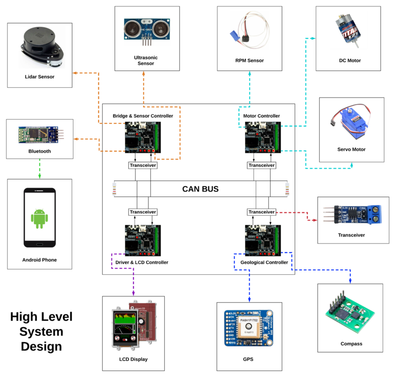
The project was divided into 7 modules:
- Bridge and Sensor Controller
- Motor Controller
- Geological Controller
- Driver and LCD Controller
- Hardware Integration
- Android Application
- Testing & Code Review
RC Car Objectives
     1. Driver and LCD Controller - Handles algorithms for obstacle avoidance, route maneuvering, and waypoints
     2. Geological Controller - Recieves coordinates from GPS and Heading from Compass for navigation
     3. Motor Controller - Controls movements of the RC Car
     4. Bridge and Sensor Controller - Detects surrounding objects and interfaces android application to controller via bluetooth
Team Objectives
Team Members and Responsibilities
Gitlab Project Link - CAN-STER Truck
- Niket Naidu LinkedIn Gitlab
- Geological Controller
- Driver and LCD Controller
- Testing & Code Review
- Android Application
Administrative Responsibilities
- Team Lead - Niket Naidu
- Git Repository Manager - Niket Naidu
- Bill Of Materials Manager - Akhil Cherukuri
- Wiki Report Manager - Akhil Cherukuri
Schedule
| Week# | Start Date | End Date | Task | Status |
|---|---|---|---|---|
| 1 | 02/11/2020 | 02/17/2020 |
|
|
| 2 | 02/18/2020 | 02/24/2020 |
|
|
| 3 | 02/25/2020 | 03/02/2020 |
|
|
| 4 | 03/03/2020 | 03/09/2020 |
|
|
| 5 | 03/10/2020 | 03/16/2020 |
|
|
| 6 | 03/17/2020 | 03/23/2020 |
|
|
| 7 | 03/24/2020 | 03/30/2020 |
|
|
| 8 | 03/31/2020 | 04/06/2020 |
|
|
| 9 | 04/07/2020 | 04/13/2020 |
|
|
| 10 | 04/14/2020 | 04/20/2020 |
|
|
| 11 | 04/21/2020 | 04/27/2020 |
|
|
| 12 | 04/28/2020 | 05/04/2020 |
|
|
| 13 | 05/05/2020 | 05/21/2020 |
|
|
Bill Of Materials
| Item# | Part Description | Part Model & Vendor | Quantity | Cost in USD |
|---|---|---|---|---|
| 1 | Microcontroller Boards | SJ2 Boards (Purchased from Preet Kang) | 4 | $200.00 |
| 2 | CAN Transceivers | Waveshare SN65HVD230 | 12 | $54.48 |
| 3 | RC Car | Traxxas 2WD RTR with 2.4Ghz Radio | 1 | $260.00 |
| 4 | Lithium-Ion Battery | Traxxas 7600mAh 2S 7.4V 25C iD LiPo Battery Pack | 1 | $75.00 |
| 5 | Lithium-Ion Battery Charger | Traxxas 2970 EZ-Peak Plus 4-Amp NiMH/LiPo Fast Charger | 1 | $50.00 |
| 6 | Compass Breakout Board | DFRobot CMPS11 Compass | 1 | $29.99 |
| 7 | Bluetooth Breakout Board | DSD TECH Bluetooth HC-05 | 1 | $8.49 |
| 8 | LIDAR Sensor | SEEED STUDIO RPLIDAR A1M8 | 1 | $109.99 |
| 9 | RPM Sensor | Traxxas 6520 RPM Sensor | 1 | $13.70 |
| 10 | GPS Breakout Board | Adafruit Ultimate GPS Breakout v3 | 1 | $44.30 |
| 11 | LCD Display | 4Dsystems 3.2 TFT-LCD ULCD-32PTU | 1 | $79.00 |
| 12 | Ultrasonic Sensors | ELEGOO HC-SR04 Ultrasonic Module | 5 | $12.00 |
| 13 | GPS Antenna | Generic | 1 | $ |
| 14 | PCB Fabrication | JLCPCB | 5 | $40.15 |
| 15 | Miscellaneous | Amazon,Mouser Electronics,Digikey,Anchor Electronics | ~ | $48.07 |
| Total | $1025.17 |
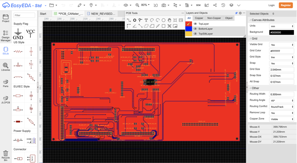
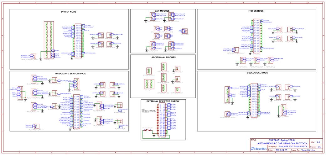
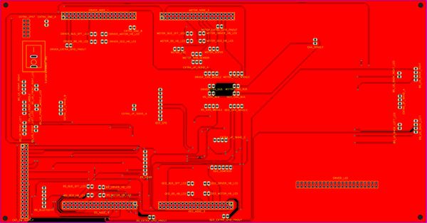
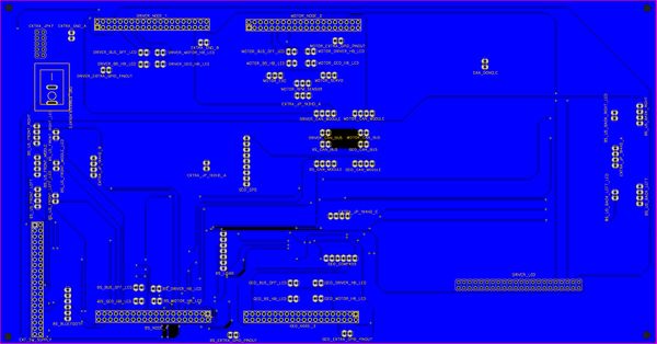
Printed Circuit Board
Design And Architecture
Power Section
Fabrication
Challenges
CAN Communication
<Talk about your message IDs or communication strategy, such as periodic transmission, MIA management, etc.>
Hardware Design
<Show your CAN bus hardware design>
DBC File
DBC FILE: Gitlab
VERSION ""

NS_ :
	BA_
	BA_DEF_
	BA_DEF_DEF_
	BA_DEF_DEF_REL_
	BA_DEF_REL_
	BA_DEF_SGTYPE_
	BA_REL_
	BA_SGTYPE_
	BO_TX_BU_
	BU_BO_REL_
	BU_EV_REL_
	BU_SG_REL_
	CAT_
	CAT_DEF_
	CM_
	ENVVAR_DATA_
	EV_DATA_
	FILTER
	NS_DESC_
	SGTYPE_
	SGTYPE_VAL_
	SG_MUL_VAL_
	SIGTYPE_VALTYPE_
	SIG_GROUP_
	SIG_TYPE_REF_
	SIG_VALTYPE_
	VAL_
	VAL_TABLE_

BS_:

BU_: DBG DRIVER IO MOTOR SENSOR GEO


BO_ 100 DRIVER_HEARTBEAT: 1 DRIVER
 SG_ DRIVER_HEARTBEAT_cmd : 0|8@1+ (1,0) [0|0] "" SENSOR,MOTOR

BO_ 101 SENSOR_HEARTBEAT: 1 SENSOR
 SG_ SENSOR_HEARTBEAT_cmd: 0|8@1+ (1,0) [0|0] "" DRIVER,GEO

BO_ 102 GEO_HEARTBEAT: 1 GEO
 SG_ GEO_HEARTBEAT_cmd: 0|8@1+ (1,0) [0|0] "" DRIVER,SENSOR

BO_ 103 MOTOR_HEARTBEAT: 1 MOTOR
 SG_ MOTOR_HEARTBEAT_cmd: 0|8@1+ (1,0) [0|0] "" DRIVER

BO_ 200 SENSOR_SONARS: 4 SENSOR
 SG_ SENSOR_SONARS_left : 0|10@1+ (1,0) [0|800] "inch" DRIVER
 SG_ SENSOR_SONARS_right : 10|10@1+ (1,0) [0|0] "inch" DRIVER
 SG_ SENSOR_SONARS_middle : 20|10@1+ (1,0) [0|0] "inch" DRIVER

BO_ 210 SENSOR_LIDAR: 8 SENSOR
 SG_ SENSOR_LIDAR_middle: 0|16@1+ (1,0) [0|0] "" DRIVER
 SG_ SENSOR_LIDAR_slight_left: 16|16@1+ (1,0) [0|0] "" DRIVER
 SG_ SENSOR_LIDAR_slight_right: 32|16@1+ (1,0) [0|0] "" DRIVER
 SG_ SENSOR_LIDAR_back: 48|16@1+ (1,0) [0|0] "" DRIVER

BO_ 220 SENSOR_BT_COORDINATES: 8 SENSOR
 SG_ SENSOR_BT_COORDINATES_latitude: 0|32@1+ (0.0001,0) [0|0] "" GEO
 SG_ SENSOR_BT_COORDINATES_longitude: 32|32@1+ (0.0001,0) [0|0] "" GEO

BO_ 300 GEO_DEGREE: 8 GEO
 SG_ GEO_DEGREE_current: 0|32@1+ (0.1,0) [0|0] "" DRIVER
 SG_ GEO_DEGREE_required: 32|32@1+ (0.1,0) [0|0] "" DRIVER

BO_ 400 DRIVER_STEERING: 8 DRIVER
 SG_ DRIVER_STEERING_direction: 0|8@1- (1,0) [-2|2] "" MOTOR
 SG_ DRIVER_STEERING_speed: 8|32@1+ (0.1, 0) [0|60] "kph" MOTOR

BO_ 500 MOTOR_INFO: 4 MOTOR
 SG_ MOTOR_INFO_rpm: 0|32@1+ (0.1,0) [0|0] "" DRIVER

CM_ BU_ DRIVER "The driver controller driving the car";
CM_ BU_ MOTOR "The motor controller of the car";
CM_ BU_ SENSOR "The sensor controller of the car";
CM_ BU_ GEO "The geo controller of the car";

CM_ BO_ 100 "Driver Sync message used to synchronize the controllers";
CM_ BO_ 101 "Sensor Sync message used to synchronize the controllers";
CM_ BO_ 102 "Geo Sync message used to synchronize the controllers";
CM_ BO_ 103 "Motor Sync message used to synchronize the controllers";
CM_ BO_ 200 "Ultrasonic Sensor values sent by Sensor Node";
CM_ BO_ 210 "Lidar Sector values sent by Sensor Node";
CM_ BO_ 220 "Coordinate BT values sent by Sensor Node";
CM_ BO_ 300 "Current and computed degree values sent by Geo Node";
CM_ BO_ 400 "Steering direction and speed values sent by Driver Node";
CM_ BO_ 500 "Information values sent by Motor Node";

CM_ SG_ 100 DRIVER_HEARTBEAT_cmd "Heartbeat command from the driver";
CM_ SG_ 101 SENSOR_HEARTBEAT_cmd "Heartbeat command from the sensor";
CM_ SG_ 102 GEO_HEARTBEAT_cmd "Heartbeat command from the geological node";
CM_ SG_ 103 MOTOR_HEARTBEAT_cmd "Heartbeat command from the motor";

CM_ SG_ 200 SENSOR_SONARS_left "Ultrasonic Sensor attached to the left side";
CM_ SG_ 200 SENSOR_SONARS_right "Ultrasonic Sensor attached to the right side";
CM_ SG_ 200 SENSOR_SONARS_middle "Ultrasonic Sensor attached to the middle";

CM_ SG_ 210 SENSOR_LIDAR_middle "Lidar sensing the middle sector (-15 to 15)";
CM_ SG_ 210 SENSOR_LIDAR_slight_left "Lidar sensing the slight left sector (-45 to -15)";
CM_ SG_ 210 SENSOR_LIDAR_slight_right "Lidar sensing the slight right sector (15 to 45)";
CM_ SG_ 210 SENSOR_LIDAR_back "Lidar sensing the back of the car (165 to 195)";

CM_ SG_ 220 SENSOR_BT_COORDINATES_latitude "Destination Latitude received over Bluetooth";
CM_ SG_ 220 SENSOR_BT_COORDINATES_longitude "Destination Longitude received over Bluetooth";

CM_ SG_ 300 GEO_DEGREE_current "Current Geo Degree relative to true north";
CM_ SG_ 300 GEO_DEGREE_required "Calculated Geo Degree computed by Haversine Formula";

CM_ SG_ 400 DRIVER_STEERING_direction "Calculated Driver Steering values for Motor";
CM_ SG_ 400 DRIVER_STEERING_speed "Calculated Driver speed values for Motor";

CM_ SG_ 500 MOTOR_INFO_rpm "Feedback RPM (speed) sent by Motor";

BA_DEF_ "BusType" STRING ;
BA_DEF_ BO_ "GenMsgCycleTime" INT 0 0;
BA_DEF_ SG_ "FieldType" STRING ;

BA_DEF_DEF_ "BusType" "CAN";
BA_DEF_DEF_ "FieldType" "";
BA_DEF_DEF_ "GenMsgCycleTime" 0;

BA_ "GenMsgCycleTime" BO_ 100 1000;
BA_ "GenMsgCycleTime" BO_ 200 50;

BA_ "FieldType" SG_ 100 DRIVER_HEARTBEAT_cmd "DRIVER_HEARTBEAT_cmd";
BA_ "FieldType" SG_ 101 SENSOR_HEARTBEAT_cmd "SENSOR_HEARTBEAT_cmd";
BA_ "FieldType" SG_ 102 GEO_HEARTBEAT_cmd "GEO_HEARTBEAT_cmd";
BA_ "FieldType" SG_ 103 MOTOR_HEARTBEAT_cmd "MOTOR_HEARTBEAT_cmd";


VAL_ 100 DRIVER_HEARTBEAT_cmd 2 "DRIVER_HEARTBEAT_cmd_REBOOT" 1 "DRIVER_HEARTBEAT_cmd_SYNC" 0 "DRIVER_HEARTBEAT_cmd_NOOP" ;
VAL_ 101 SENSOR_HEARTBEAT_cmd 2 "SENSOR_HEARTBEAT_cmd_REBOOT" 1 "SENSOR_HEARTBEAT_cmd_SYNC" 0 "SENSOR_HEARTBEAT_cmd_NOOP" ;
VAL_ 102 GEO_HEARTBEAT_cmd 2 "GEO_HEARTBEAT_cmd_REBOOT" 1 "GEO_HEARTBEAT_cmd_SYNC" 0 "GEO_HEARTBEAT_cmd_NOOP" ;
VAL_ 103 MOTOR_HEARTBEAT_cmd 2 "MOTOR_HEARTBEAT_cmd_REBOOT" 1 "MOTOR_HEARTBEAT_cmd_SYNC" 0 "MOTOR_HEARTBEAT_cmd_NOOP" ;
Motor Controller
<Picture and link to Gitlab>
Hardware Design
Software Design
<List the code modules that are being called periodically.>
Technical Challenges
< List of problems and their detailed resolutions>
Geological Controller
<Picture and link to Gitlab>
Hardware Design
Software Design
<List the code modules that are being called periodically.>
Technical Challenges
< List of problems and their detailed resolutions>
Sensor [Bridge and Sensor Controller]
<Picture and link to Gitlab>
Hardware Design
Software Design
<List the code modules that are being called periodically.>
Technical Challenges
< List of problems and their detailed resolutions>
Bridge [Bridge and Sensor Controller]
<Picture and link to Gitlab>
Hardware Design
Software Design
<List the code modules that are being called periodically.>
Technical Challenges
< List of problems and their detailed resolutions>
Driver [Driver and LCD Controller]
<Picture and link to Gitlab>
Hardware Design
Software Design
<List the code modules that are being called periodically.>
Technical Challenges
< List of problems and their detailed resolutions>
LCD [Driver and LCD Controller]
<Picture and link to Gitlab>
Hardware Design
Software Design
<List the code modules that are being called periodically.>
Technical Challenges
< List of problems and their detailed resolutions>
Android Application
<Picture and link to Gitlab>
Hardware Design
Software Design
<List the code modules that are being called periodically.>
Technical Challenges
< List of problems and their detailed resolutions>
Conclusion
<Organized summary of the project>
<What did you learn?>
Project Video
Project Source Code
Advise for Future Students
<Bullet points and discussion>
Acknowledgement
