Difference between revisions of "F19: T-Rex Run!"
Proj user9 (talk | contribs) (→Software Design) |
Proj user9 (talk | contribs) (→Software Design) |
||
| Line 373: | Line 373: | ||
[[File:Flowchart_T-Rex_Run.PNG|T-Rex Run Flowchart]] | [[File:Flowchart_T-Rex_Run.PNG|T-Rex Run Flowchart]] | ||
| + | |||
| + | '''Game Logic:''' | ||
| + | |||
| + | A matrixbuf array maps onto the LED Display Matrix. A value overwritten in this two-dimensional buffer updates the corresponding Pixel value of the LED Matrix. The drawPixel function maps onto the matrixbuf and updates the corresponding value. | ||
| + | |||
| + | There are different tasks that handle the generation of the Dinosaur, generation of obstacles, collision detection, shifting of obstacles as well as maintaining the scoring of the game. These tasks run in parallel and are scheduled with the help of of the task scheduler that updates the display regularly | ||
| + | |||
| + | There were three algorithms that were designed for the implementation of the game. | ||
| + | |||
| + | '''1) Dinosaur Generation and Hopping on Button Press :''' | ||
| + | |||
| + | <syntaxhighlight lang="c"> | ||
| + | void buttonpress(void *p) { | ||
| + | while (1) { | ||
| + | for (uint8_t col = 0; col < 32; col++) { | ||
| + | matrixbuf[28][col] = 0x18; | ||
| + | matrixbuf[29][col] = 0x18; | ||
| + | matrixbuf[30][col] = 0x18; | ||
| + | } | ||
| + | LPC_GPIO2->PIN |= (1 << 3); | ||
| + | if (0 == !(LPC_GPIO0->PIN & (1 << 30))) { | ||
| + | HOP_FLAG = 1; | ||
| + | cleardino(); | ||
| + | xSemaphoreGive(hop); | ||
| + | |||
| + | } else { | ||
| + | vTaskDelay(1000); | ||
| + | drawdino(); | ||
| + | } | ||
| + | } | ||
| + | } | ||
| + | |||
| + | void make_it_hop(void *p) { | ||
| + | while (1) { | ||
| + | xSemaphoreTake(hop, portMAX_DELAY); | ||
| + | cleardino(); | ||
| + | hopdino(); | ||
| + | vTaskDelay(100); | ||
| + | clearhopdino(); | ||
| + | drawdino(); | ||
| + | LPC_GPIO0->PIN |= (1 << 30); | ||
| + | HOP_FLAG = 0; | ||
| + | } | ||
| + | } | ||
| + | |||
| + | void drawdino() { | ||
| + | matrixbuf[24 - 1][4] = 0x30; | ||
| + | matrixbuf[24 - 1][5] = 0x30; | ||
| + | matrixbuf[25 - 1][4] = 0x30; | ||
| + | matrixbuf[26 - 1][4] = 0x30; | ||
| + | matrixbuf[26 - 1][5] = 0x30; | ||
| + | matrixbuf[27 - 1][3] = 0x30; | ||
| + | matrixbuf[27 - 1][4] = 0x30; | ||
| + | matrixbuf[27 - 1][3] = 0x30; | ||
| + | matrixbuf[27 - 1][4] = 0x30; | ||
| + | matrixbuf[27 - 1][5] = 0x30; | ||
| + | matrixbuf[28 - 1][3] = 0x30; | ||
| + | matrixbuf[28 - 1][4] = 0x30; | ||
| + | matrixbuf[28 - 1][5] = 0x30; | ||
| + | } | ||
| + | |||
| + | void cleardino() { | ||
| + | matrixbuf[24 - 1][4] = 0x00; | ||
| + | matrixbuf[24 - 1][5] = 0x00; | ||
| + | matrixbuf[25 - 1][4] = 0x00; | ||
| + | matrixbuf[26 - 1][4] = 0x00; | ||
| + | matrixbuf[26 - 1][5] = 0x00; | ||
| + | matrixbuf[27 - 1][3] = 0x00; | ||
| + | matrixbuf[27 - 1][4] = 0x00; | ||
| + | matrixbuf[27 - 1][5] = 0x00; | ||
| + | matrixbuf[28 - 1][3] = 0x00; | ||
| + | matrixbuf[28 - 1][4] = 0x00; | ||
| + | matrixbuf[28 - 1][5] = 0x00; | ||
| + | } | ||
| + | |||
| + | void hopdino() { | ||
| + | matrixbuf[18][4] = 0x30; | ||
| + | matrixbuf[18][5] = 0x30; | ||
| + | matrixbuf[19][4] = 0x30; | ||
| + | matrixbuf[20][4] = 0x30; | ||
| + | matrixbuf[20][5] = 0x30; | ||
| + | matrixbuf[21][3] = 0x30; | ||
| + | matrixbuf[21][4] = 0x30; | ||
| + | matrixbuf[21][5] = 0x30; | ||
| + | matrixbuf[22][3] = 0x30; | ||
| + | matrixbuf[22][4] = 0x30; | ||
| + | matrixbuf[22][5] = 0x30; | ||
| + | } | ||
| + | |||
| + | void clearhopdino() { | ||
| + | matrixbuf[18][4] = 0x00; | ||
| + | matrixbuf[18][5] = 0x00; | ||
| + | matrixbuf[19][4] = 0x00; | ||
| + | matrixbuf[20][4] = 0x00; | ||
| + | matrixbuf[20][5] = 0x00; | ||
| + | matrixbuf[21][3] = 0x00; | ||
| + | matrixbuf[21][4] = 0x00; | ||
| + | matrixbuf[21][5] = 0x00; | ||
| + | matrixbuf[22][3] = 0x00; | ||
| + | matrixbuf[22][4] = 0x00; | ||
| + | matrixbuf[22][5] = 0x00; | ||
| + | } | ||
| + | </syntaxhighlight> | ||
| + | <BR/> | ||
==='''Printed Circuit Board Design'''=== | ==='''Printed Circuit Board Design'''=== | ||
Revision as of 00:32, 4 December 2019
T-Rex Run!
Contents
Abstract
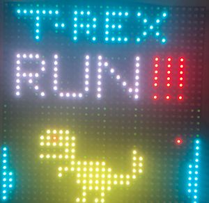
T-Rex Run! game is an adaptation of popular chrome browser offline game in which the player steers a T-Rex dinosaur through increasingly dangerous landscapes to escape a tree of doom. The game uses simple pixel art and sound to replicate the style of 1980s arcade games. The player will be able to control the game by using switch buttons available on the Sjtwo-C microcontroller. The main goal behind the project is to understand the basics of graphics programming in the C language on a microcontroller.
Objectives & Introduction
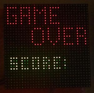
The primary objective of this project is to write efficient code to develop a game using FreeRTOS and SJTwo Board. SJTwo Boards act as the heart of the project which acts as the controller of the game which we primarily test using onboard switch controlled with GPIO. The main objective which we are achieving with is to use the accelerometer sensor as a controlling aspect. The accelerometer sensor on the SJTwo board which is connected via I2C is used to register the controller orientation and according to the orientation obtained by the sensor, game logic decides whether to make dinosaur jump up or not. The obstacles are generated randomly and are moved from left to right on the LED matrix. If dinosaur collides with any of the obstacles its game over. The speed of obstacle movement increases as the levels goes up.
The project includes the following modules:
1. Controller: One SJTwo board is used as the controller. It transmits orientation to the processor.
2. Display Module: Adafruit 32x32 Led Matrix display is used to display the game. This is driven by the GPIO pins on the master SJOTwo Board.
Team Members & Responsibilities
- Tina Ruchandani
- Collision Detection.
- Wiki Page Updates.
- Tushar Tarihalkar
- PCB and Hardware Design.
- Software Design (Dinosaur Design and Control).
- Wiki Page Updates.
- Wenyan He
- Random Obstacle Generation.
- Mahesh Mohan Shinde
- LED Matrix Interface.
- Testing.
- Wiki Page Updates.
Schedule
| Week | Date | Task | Status |
|---|---|---|---|
| 1 | 10/08 |
|
|
| 2 | 10/10 |
|
|
| 3 | 10/15 |
|
|
| 4 | 10/29 |
|
|
| 5 | 11/13 |
|
|
| 6 | 11/19 |
|
|
| 7 | 11/26 |
|
|
| 8 | 12/03 |
|
|
| 8 | 12/10 |
|
|
| 8 | 12/18 |
|
|
Parts List & Cost
| Part | # | Cost | Source |
|---|---|---|---|
| SJ2 Board | 1 | $55.00 | Preet |
| Adafruit RGB (32x32) LED Matrix Display | 1 | $60.80 | Amazon |
| PCB Fabrication | 1 | $20.00 | JLC PCB |
| 5V/4A Power Adapter | 1 | $8.99 | Amazon |
| Female DC Power adapter - 2.1mm jack | 1 | $2.99 | Adafruit |
| Jumper Wires | 1 | $6.99 | Amazon |
Design & Implementation
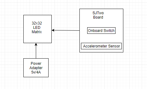
The block diagram for the project given below depicts the flow of the game
The design section can go over your hardware and software design. Organize this section using sub-sections that go over your design and implementation.
Hardware Design
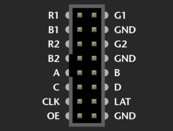
The hardware design for the project consists of a 32x32 RGB LED matrix operated using SJTWO Board (LPC4078). The RGB LED matrix is controlled using GPIO pins available on the microcontroller. The functioning of the LED matrix is basically controlled by the four data lines A, B, C and D which can be addressed and used to control each LED on the Matrix.
LED Matrix specifications:
- 190.5mm x 190.5mm x 14mm / 7.5" x 7.5" x 0.55"
- Panel weight with IDC cables and power cable: 357.51g
- 5V regulated power input, 4A max (all LEDs on)
- 5V data logic level input
- 2000 mcd LEDs on 6mm pitch
- 1/16 scan rate
| Label | Name | Pin Function |
|---|---|---|
| 1 | R1 | Red data for top half of the LED Matrix |
| 2 | G1 | Green data for top half of the LED Matrix |
| 3 | B1 | Blue data for top half of the LED Matrix |
| 4 | A | Select line A |
| 5 | B | Select line B |
| 6 | C | Select line C |
| 7 | D | Select line D |
| 8 | R2 | Red data for bottom half of the LED Matrix |
| 9 | B2 | Blue data for bottom half of the LED Matrix |
| 10 | G2 | Green data for bottom half of the LED Matrix |
| 11 | CLK | CLOCK Pin |
| 12 | LAT | LATCH |
| 13 | OE | Output Enable |
| 14 | GND | Ground |
LED Matrix Control
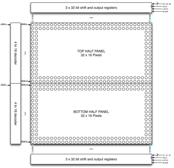
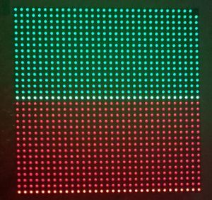
The 32x32 LED matrix consists of 1024 LEDs arranged in 32 rows and 32 columns each, with each led having a separate Red, Green and Blue LED chips assembled together as a single unit. This 32x32 LED matrix comprises of 2 of 16x32 led matrices placed vertically to each other. There are different drivers for controlling the corresponding rows and columns each. In order to illuminate a particular led, one needs to access and control the corresponding row and column (just like in coordinate-axis). To change the color of a particular led, each led must be controlled using the driver for that row and column.
The matrix pixels are controlled by 6 drivers, 3 for the top half of the matrix(R1,G1,B1) and 3 for the bottom half(R2,G2,B2). The three drivers for R, G and B share a SCLK, Latch and BLANK signal. The top half pixels of the matrix controlled by R1, G1,B1 are rows 0-15 and the second half controlled by R2,G2,B2 are rows 16-31. The display is multiplexed at a duty cycle of 1/16, this means that one row in the top half and one row in the bottom half will be illuminated at a time. In order to display an image, the row and column LEDs for that image must be turned “ON”, therefore, the entire panel must be scanned at a rate(speed) at which it appears that the image is being displayed without flickering. To display different colors and different brightness levels, the LED chips of corresponding row and column must be adjusted by varying the amount and time that each LED chip is turned on during each cycle.
Hardware Interface
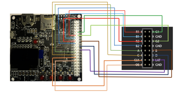
The connections to the REG LED matrix with the corresponding microcontroller (LPC4078) are as follows:
| SJTWO Board pins | LED matrix pin | Pin Function |
|---|---|---|
| P0.8 | R1 | Red data for top half of the LED Matrix |
| P0.7 | G1 | Green data for top half of the LED Matrix |
| P0.26 | B1 | Blue data for top half of the LED Matrix |
| P2.2 | A | Select line A |
| P1.30 | B | Select line B |
| P2.5 | C | Select line C |
| P1.29 | D | Select line D |
| P1.31 | R2 | Red data for bottom half of the LED Matrix |
| P1.20 | B2 | Blue data for bottom half of the LED Matrix |
| P0.9 | G2 | Green data for bottom half of the LED Matrix |
| P2.7 | CLK | CLOCK Pin |
| P2.1 | LAT | LATCH |
| P2.9 | OE | Output Enable |
| GND | GND | Ground |
Software Design
The following state flow diagram illustrates the tasks for software implementation. The major thing behind the implementation of T-Rex Run game is a thorough understanding of the control of the LED Matrix.
Game Logic:
A matrixbuf array maps onto the LED Display Matrix. A value overwritten in this two-dimensional buffer updates the corresponding Pixel value of the LED Matrix. The drawPixel function maps onto the matrixbuf and updates the corresponding value.
There are different tasks that handle the generation of the Dinosaur, generation of obstacles, collision detection, shifting of obstacles as well as maintaining the scoring of the game. These tasks run in parallel and are scheduled with the help of of the task scheduler that updates the display regularly
There were three algorithms that were designed for the implementation of the game.
1) Dinosaur Generation and Hopping on Button Press :
void buttonpress(void *p) {
  while (1) {
    for (uint8_t col = 0; col < 32; col++) {
      matrixbuf[28][col] = 0x18;
      matrixbuf[29][col] = 0x18;
      matrixbuf[30][col] = 0x18;
    }
    LPC_GPIO2->PIN |= (1 << 3);
    if (0 == !(LPC_GPIO0->PIN & (1 << 30))) {
      HOP_FLAG = 1;
      cleardino();
      xSemaphoreGive(hop);

    } else {
      vTaskDelay(1000);
      drawdino();
    }
  }
}

void make_it_hop(void *p) {
  while (1) {
    xSemaphoreTake(hop, portMAX_DELAY);
    cleardino();
    hopdino();
    vTaskDelay(100);
    clearhopdino();
    drawdino();
    LPC_GPIO0->PIN |= (1 << 30);
    HOP_FLAG = 0;
  }
}

void drawdino() {
  matrixbuf[24 - 1][4] = 0x30;
  matrixbuf[24 - 1][5] = 0x30;
  matrixbuf[25 - 1][4] = 0x30;
  matrixbuf[26 - 1][4] = 0x30;
  matrixbuf[26 - 1][5] = 0x30;
  matrixbuf[27 - 1][3] = 0x30;
  matrixbuf[27 - 1][4] = 0x30;
  matrixbuf[27 - 1][3] = 0x30;
  matrixbuf[27 - 1][4] = 0x30;
  matrixbuf[27 - 1][5] = 0x30;
  matrixbuf[28 - 1][3] = 0x30;
  matrixbuf[28 - 1][4] = 0x30;
  matrixbuf[28 - 1][5] = 0x30;
}

void cleardino() {
  matrixbuf[24 - 1][4] = 0x00;
  matrixbuf[24 - 1][5] = 0x00;
  matrixbuf[25 - 1][4] = 0x00;
  matrixbuf[26 - 1][4] = 0x00;
  matrixbuf[26 - 1][5] = 0x00;
  matrixbuf[27 - 1][3] = 0x00;
  matrixbuf[27 - 1][4] = 0x00;
  matrixbuf[27 - 1][5] = 0x00;
  matrixbuf[28 - 1][3] = 0x00;
  matrixbuf[28 - 1][4] = 0x00;
  matrixbuf[28 - 1][5] = 0x00;
}

void hopdino() {
  matrixbuf[18][4] = 0x30;
  matrixbuf[18][5] = 0x30;
  matrixbuf[19][4] = 0x30;
  matrixbuf[20][4] = 0x30;
  matrixbuf[20][5] = 0x30;
  matrixbuf[21][3] = 0x30;
  matrixbuf[21][4] = 0x30;
  matrixbuf[21][5] = 0x30;
  matrixbuf[22][3] = 0x30;
  matrixbuf[22][4] = 0x30;
  matrixbuf[22][5] = 0x30;
}

void clearhopdino() {
  matrixbuf[18][4] = 0x00;
  matrixbuf[18][5] = 0x00;
  matrixbuf[19][4] = 0x00;
  matrixbuf[20][4] = 0x00;
  matrixbuf[20][5] = 0x00;
  matrixbuf[21][3] = 0x00;
  matrixbuf[21][4] = 0x00;
  matrixbuf[21][5] = 0x00;
  matrixbuf[22][3] = 0x00;
  matrixbuf[22][4] = 0x00;
  matrixbuf[22][5] = 0x00;
}
Printed Circuit Board Design
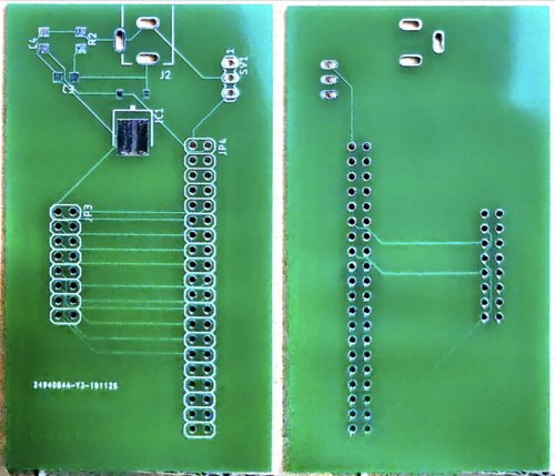
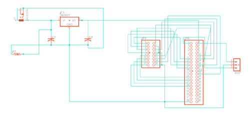
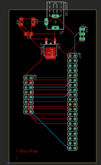
We have designed and developed a PCB in order to supply power for LPC4078 (SJTWO board) and RGB LED Matrix which is able to provide 5v and 1A supply efficiently. The PCB Layout is designed using the Eagle Software v9.5.1. The Power Supply circuit has an IC7805 voltage regulator IC and a voltage divider to fulfill the specific power requirements. IC7805 is a linear voltage regulator which has a variable output voltage ranging from 4.8 V to 5.2 V and is suitable for our application. We have used a 5V adapter in order to power our board.
Implementation
This section includes implementation, but again, not the details, just the high level. For example, you can list the steps it takes to communicate over a sensor, or the steps needed to write a page of memory onto SPI Flash. You can include sub-sections for each of your component implementation.
Testing & Technical Challenges
1) Display Driver Implementation: When we started implementing an initial driver for testing LED matrix for basic shapes, figures, number as well as controlling individual pixel, we tried to replicate the Adafruit library since the library was primarily designed to work with Arduino. Hence, we were unsuccessful in porting the library entirely. Then we moved on with reading various Sparkfun libraries where we understood the basic working of RGB LED matrix and decided to control over a single row first and then over a single pixel. We first implemented a function to first select the row according to A, B, C and D signals and write the corresponding pixel values of all LEDs in those rows with the updated values from the frame buffer. The values of the pixels were set only within the clock trigger. In the end, the pixel values were latched before the output enable signal was asserted again. This function was called from a periodic task with the 2.5-millisecond delay in order to get the refresh rate of the display as 2.5 milliseconds. This helped us to get control over individual pixels of the matrix.
Bug/issue name
Discuss the issue and resolution.
Conclusion
Conclude your project here. You can recap your testing and problems. You should address the "so what" part here to indicate what you ultimately learnt from this project. How has this project increased your knowledge?
Project Video
Upload a video of your project and post the link here.
Project Source Code
References
Acknowledgement
Any acknowledgement that you may wish to provide can be included here.
References Used
- 32x32 LED Matrix by Adafruit
- Adafruit Github Library
- Adafruit Github Library
- WikiPage by Preetpal Kang
Appendix
You can list the references you used.

