Difference between revisions of "F19: Space Impact"
Proj user3 (talk | contribs) (→Hardware Interface) |
Proj user3 (talk | contribs) (→Parts List & Cost) |
||
| Line 178: | Line 178: | ||
| PCB | | PCB | ||
| JLC PCB | | JLC PCB | ||
| + | | 1 | ||
| + | | $10 | ||
| + | |- | ||
| + | |- | ||
| + | ! scope="row"| 4 | ||
| + | | Audio Decoder | ||
| + | | [https://www.amazon.com/gp/product/B01JCI23JG/ref=ppx_yo_dt_b_asin_title_o00_s00?ie=UTF8&psc=1 Aideepen] | ||
| 1 | | 1 | ||
| $10 | | $10 | ||
Revision as of 00:44, 25 November 2019
Contents
Abstract
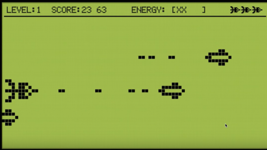
Space Impact is a classic game from the days of the Nokia era. Our objective is to design a game in which a player is prompted to protect a spaceship from incoming missiles by moving the ship up and down. The player will also have the ability to fire back at the incoming enemies. The enemy ship's movements will speed up as the game progresses, increasing the difficulty of the game.
Example Link: https://www.youtube.com/watch?v=jh49RWFnZHk
Objectives & Introduction
Introduction:
We intended to design an embedded system whose sole purpose is to run an arcade game with just an RGB LED Matrix and a microcontroller. The game itself involves a user controlling a spaceship through an accelerometer, guiding the spaceship across many enemy spacecraft and obstacles. These obstacles are generated randomly and appear from the right-hand side of the screen. The player shoots the obstacles with bullets by pressing a button clearing a path for him or herself. The game starts on the press of the button and ends when the players runs out of health by taking too many hits. The objective of the game is to survive as long as possible acquiring as many points as he or she can.
Objectives:
- Interfacing the RGB LED Matrix with SJTwo Microcontroller
- Coding simple to use display functions for displaying spacecraft, bullets, enemies at any given position
- Randomizer to generate random locations for enemies
- Tasks that can move the spacecraft and detect collisions between:
- Bullet to Bullet (Cancels out)
- Bullet to Enemy (Clears enemy and increments score)
- Enemy bullet to ship (Damage to ship and decrements energy bar)
- Ship to Ship (Extra damage to energy bar)
- Interrupt to be generated on press of button to start game/fire bullets
- Score Counter and Energy Counter to be displayed at the top and updated in real time as the game progresses
- Title Screen and Game Over screens
- MP3 driver for playing audio
Team Members & Responsibilities:
- Nikhil Pabbisetty: Wiki Page, LED Matrix Interfacing, Game Design
- Hari Haran Kura: Game Design, Game Sounds, Github Repository
- Daniel Tsai: Game Design, PCB Design
Schedule
| Week# | Date | Task | Current Progress | Actual Completion Date |
|---|---|---|---|---|
| 1 | 10/01/2019 |
|
|
|
| 2 | 10/15/2019 |
|
|
|
| 3 | 10/22/2019 |
|
|
|
| 4 | 10/29/2019 |
|
|
|
| 5 | 11/05/2019 |
|
|
|
| 6 | 11/12/2019 |
|
|
|
| 7 | 11/19/2019 |
|
In Progress | N/A |
| 8 | 11/26/2019 |
|
In Progress | N/A |
| 9 | 12/03/2019 |
|
In Progress | N/A |
| 10 | 12/10/2019 |
|
In Progress | N/A |
Parts List & Cost
| S.No. | Parts | Seller | Quantity | Price |
|---|---|---|---|---|
| 1 | SJTwo Microcontroller | Preetpal Kang | 1 | $50 |
| 2 | RGB LED Matrix Panel - 64x64 | Sparkfun | 1 | $85 |
| 3 | PCB | JLC PCB | 1 | $10 |
| 4 | Audio Decoder | Aideepen | 1 | $10 |
Design & Implementation
The design section can go over your hardware and software design. Organize this section using sub-sections that go over your design and implementation.
Hardware Design
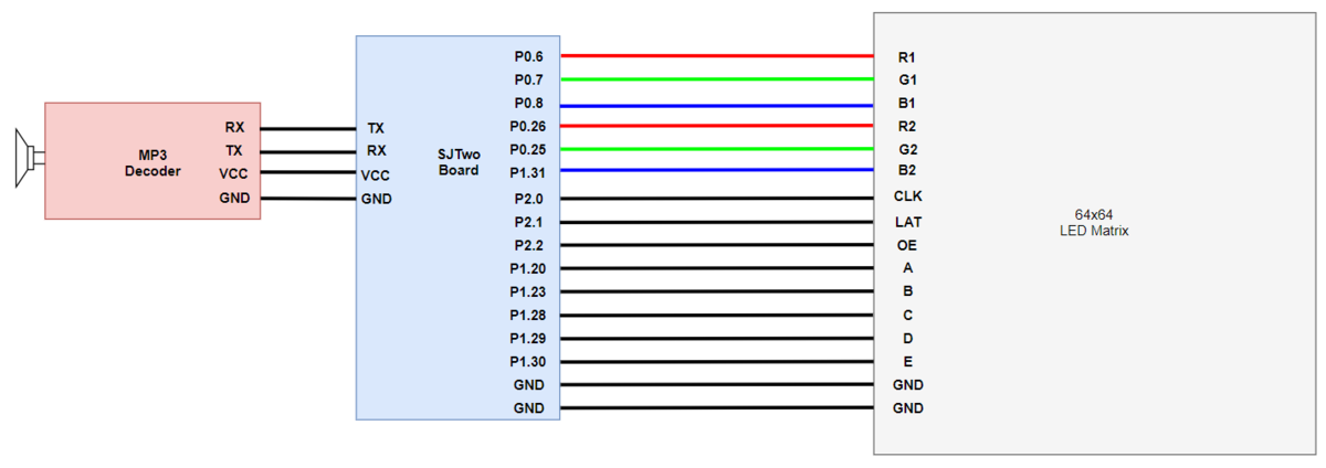
Our design for LED control was based on the below simplified block diagram. We are using the SJTwo board GPIO pins for turning on and off an LED in the LED matrix. R1 G1 B1 is used to control the colors of LEDs in the top half of the matrix (0-31 rows) and R2 G2 B2 in the bottom half of the matrix (32-63 rows). GPIO were also selected for the CLK, LAT and OE purposes. ABCDE pins are used for row selection. Each pin is made high or low based on the requirement. Using these pins we can form our LED animation based on transmission pattern.
Hardware Interface
For our design, we would prefer the most common used buses nowadays in industry and base on what we have learned in our CMPE244 courses, it would be either I2C or SPI. It also need to be compatible with our controller, so the key factor to decide how our design would be is which one out of these two was equipped in the controller we choose.
Software Design
Show your software design. For example, if you are designing an MP3 Player, show the tasks that you are using, and what they are doing at a high level. Do not show the details of the code. For example, do not show exact code, but you may show psuedocode and fragments of code. Keep in mind that you are showing DESIGN of your software, not the inner workings of it.
Implementation
This section includes implementation, but again, not the details, just the high level. For example, you can list the steps it takes to communicate over a sensor, or the steps needed to write a page of memory onto SPI Flash. You can include sub-sections for each of your component implementation.
Testing & Technical Challenges
Describe the challenges of your project. What advise would you give yourself or someone else if your project can be started from scratch again? Make a smooth transition to testing section and described what it took to test your project.
Include sub-sections that list out a problem and solution, such as:
<Bug/issue name>
Discuss the issue and resolution.
Conclusion
Conclude your project here. You can recap your testing and problems. You should address the "so what" part here to indicate what you ultimately learnt from this project. How has this project increased your knowledge?
Project Video
Upload a video of your project and post the link here.
Project Source Code
References
Acknowledgement
Any acknowledgement that you may wish to provide can be included here.
References Used
List any references used in project.
Appendix
You can list the references you used.

