Difference between revisions of "F13: Remote Control Car"
Proj user2 (talk | contribs) (→TX Board Overview) |
Proj user2 (talk | contribs) (→Testing) |
||
| Line 236: | Line 236: | ||
The TX board software and RX board software were tested independently prior to integration. Then the integration of the TX and RX board was performed in steps up to the final integrated configuration. | The TX board software and RX board software were tested independently prior to integration. Then the integration of the TX and RX board was performed in steps up to the final integrated configuration. | ||
| + | '''TX Board''' | ||
The TX board software testing consisted of printing wireless commands to the serial window to verify the accelerometer function. Although this did not mimic the timing of the actual system, since the serial port print slows the processor, it provided a baseline of the command data to be transmitted and gave the ability to develop the accelerometer value conversions. | The TX board software testing consisted of printing wireless commands to the serial window to verify the accelerometer function. Although this did not mimic the timing of the actual system, since the serial port print slows the processor, it provided a baseline of the command data to be transmitted and gave the ability to develop the accelerometer value conversions. | ||
| + | '''RX Board''' | ||
The RX board software testing consisted of using switches rather than receiving wireless commands, controlled by #define, to control the car. Some timers were used to de-bounce the switches. Also, an oscilloscope was used to verify the PWM frequency and pulse widths required by the servo and speed controller. The serial port was also used to test the features of the upside detection and tilt over detection logic. | The RX board software testing consisted of using switches rather than receiving wireless commands, controlled by #define, to control the car. Some timers were used to de-bounce the switches. Also, an oscilloscope was used to verify the PWM frequency and pulse widths required by the servo and speed controller. The serial port was also used to test the features of the upside detection and tilt over detection logic. | ||
| + | |||
| + | '''Integrated Testing''' | ||
Once both the TX and RX board were tested independently, the first integration test was to have the TX board transmit the wireless commands and have the RX board print the value to the serial port. Next, with the car sitting on a stand we determined the stability of the TX and RX boards to control the car. When it was proven that the car was reliable and stable, we drove the car in a controlled environment. | Once both the TX and RX board were tested independently, the first integration test was to have the TX board transmit the wireless commands and have the RX board print the value to the serial port. Next, with the car sitting on a stand we determined the stability of the TX and RX boards to control the car. When it was proven that the car was reliable and stable, we drove the car in a controlled environment. | ||
| − | We | + | We operated the the car in different environments, outside and inside, to ensure its reliability. We also tested the distance that the car could travel from the TX board and it found it to be around 40 feet. |
== Conclusion == | == Conclusion == | ||
Revision as of 21:06, 6 December 2013
Contents
Grading Criteria
- How well is Software & Hardware Design described?
- How well can this report be used to reproduce this project?
- Code Quality
- Overall Report Quality:
- Software Block Diagrams
- Hardware Block Diagrams
- Schematic Quality
- Quality of technical challenges and solutions adopted.
Remote Control Car
Abstract
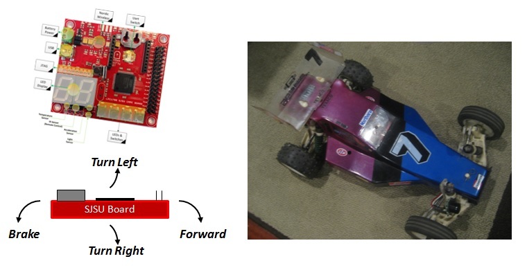
The goal of this project is to use 2 SJSU Development boards to control a remote control car. The first board will act as the controller using motion for control (throttle and steering). The second board will be mounted on the car and control the servo and motor controller.
Objectives & Introduction
RX Board Overview
The RX board provides:
- Receives wireless commands from transmitter board
- Control for steering servo and speed throttle control
- Car On/Off button
- Proximity Sensor for front obstacle avoidance
- Stability control to self-correct if starting to flip over
TX Board Overview
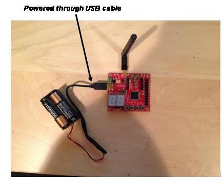
The TX board provides:
- Wireless control of R/C using tilt detection (2-channel)
- Car On/Off button
- Front Proximity Sensor On/Off button
Team Members & Responsibilities
- Alan Wang
- TX Board software development including:
- Develop driver for Acceleration Sensor (throttle and steering)
- Develop Wireless message protocol between boards
- Develop TX board software to transmit commands
- TX Board software development including:
- Curtis Woodworth
- RX Board software/hardware development including:
- Integrate hardware onto R/C Car (board, power, cable)
- Develop RX board software to control RC car
- Develop front proximity sensor detection software
- RX Board software/hardware development including:
Schedule
| Week# | Task | ECD | Completion
Date |
|---|---|---|---|
| 1 | Identify R/C Car usage and ensure operation
Identify & Order parts needed Complete Project Proposal document |
10/8 | 10/8 |
| 2 | Setup & build R/C Car
Test R/C operation with nominal controller Develop pin list for I/O use & types |
10/15 | 10/15 |
| 3 | Develop Accelerometer software driver
Develop Servo control software driver |
10/22 | 10/15 |
| 4 | Develop Transmitter data protocol
Develop Transmitter software driver Develop Proximity sensor software driver |
10/29 | 10/15 |
| 5 | Integrate accelerometer and transmitter drivers program
Integrate servo and proximity drivers into program |
11/5 | 10/29 |
| 6 | Integrate TX and RX development boards communications
Integrate & Test system with simulated R/C Car |
11/12 | 10/29 |
| 7 | Integrate & Test system with actual R/C Car | 11/19 | 11/18 |
| 8 | Demo Project
Finish report |
12/3 | 12/3 |
Parts List & Cost
| Part Number | Description | Price ($) | Qty |
|---|---|---|---|
| SJSUONE | SJSU-One Development Board | 75.00 | 2 |
| - | AA Battery Pack | 6.00 | 1 |
| RC10 | Associated RC10 Car | 305.00 | 1 |
| 410-MXc | Novak Electronic Speed Control | 90.00 | 1 |
| Stock | Pocket Rocket Motor | 25.00 | 1 |
| - | Sanyo 1400mA 7.2V Battery | 20.00 | 1 |
| S9302 | Futaba HS Steering Servo | 40.00 | 1 |
| MB1010 | LV-MaxSonar EZ1 | 30.00 | 1 |
| - | Misc Hardware | 8.00 | 1 |
| Total | 674.00 |
Design & Implementation
The design section can go over your hardware and software design. Organize this section using sub-sections that go over your design and implementation.
Hardware Design
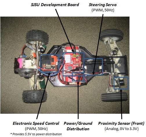
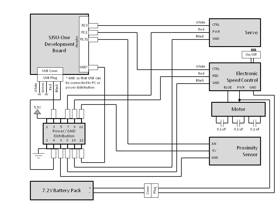
The hardware development mostly consisted of integrated the R/C car and SJSU-one development board. The custom made cables and power distribution header required planning and custom soldering. The SJSJ-one board was mounted on the R/C car using screws with plastic spacers.
Hardware Interface
In this section, you can describe how your hardware communicates, such as which BUSes used. You can discuss your driver implementation here, such that the Software Design section is isolated to talk about high level workings rather than inner working of your project.
The TX board used the following interfaces:
- Accelerometer sensor for steering and throttle control (I2C Bus)
- Nordic wireless interface for transmitting control packets (SPI Bus)
- Switches for Enable/Disable of Control and Sensor (GPIO)
- LED number display for throttle position (I2C bus)
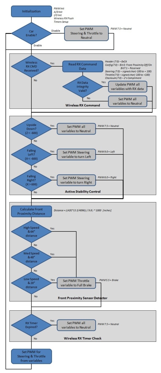
The RX board used the following interfaces:
- Nordic wireless interface for receiving control packets (SPI Bus)
- PWM interface to steering servo (50Hz refresh)
- PWM interface to electronic speed control (50Hz refresh)
- Analog to Digital Converter from proximity sensor (LPC1758)
- Accelerometer sensor to detect upside or flipping of car (I2C Bus)
- Switches for Car Enable/Disable (GPIO)
- Discrete LEDs for status such Car and Proximity Sensor Enable/Disable (GPIO)
- LED Display (numbers) for error codes (I2C bus)
Software Design
Show your software design. For example, if you are designing an MP3 Player, show the tasks that you are using, and what they are doing at a high level. Do not show the details of the code. For example, do not show exact code, but you may show psuedocode and fragments of code. Keep in mind that you are showing DESIGN of your software, not the inner workings of it.
RX Board Software Diagram
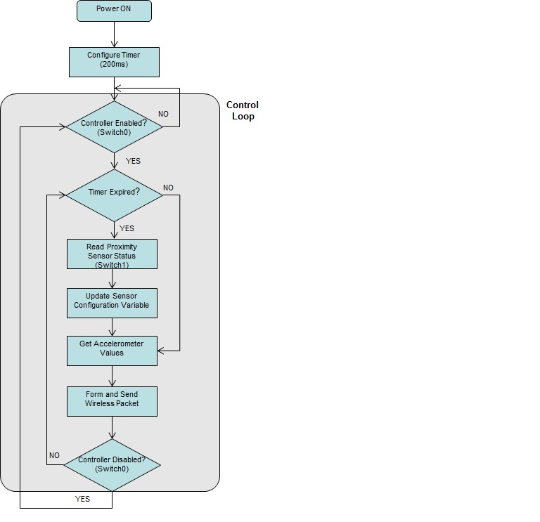
TX Board Software Diagram
Implementation
This section includes implementation, but again, not the details, just the high level. For example, you can list the steps it takes to communicate over a sensor, or the steps needed to write a page of memory onto SPI Flash. You can include sub-sections for each of your component implementation.
TX Board
Proximity Sensor Configuration
- A 200ms software timer is used to set the sensor configuration variable. At the beginning of the control loop, if the timer has expired then the switch status is read and the configuration is updated. This is to "de-bounce" the switch.
Steering and Throttle Resolution
- The 16-bit value read from the accelerometer is translated to an 8-bit value. The 8-bit value (capped at +/- 100) is then transmitted to the RX Board, to control steering and throttle. 100 steps in each direction provided smoother control and acceleration of the car.
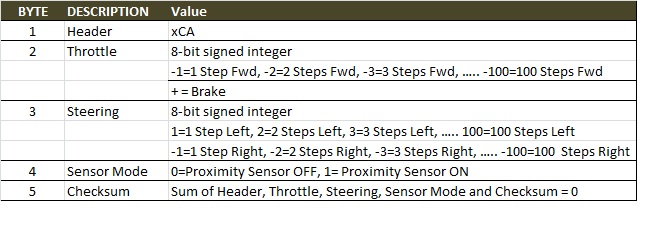
Wireless Command Format
- A header field and checksum was included with the control data to form the command packet. The format is shown below
Technical Challenges
Steering and Throttle Resolution
The initial design used 10 steps in each direction for direction and throttle. As a result, the steering was incredible jittery and acceleration of the car was difficult to control. After testing several settings, we settled on 100 steps. This allowed for smoother control with full range of steering motion.
Proximity Sensor Detection
The proximity sensor was first mounted to the front bumper of the car. When it was disabled, control of the car was normal. When enabled the car became very erratic. We later learned that the field-of-view of the sensor was cone shaped and the ground was most likely in view of the sensor. The sensor also has a minimum range detection of 6". We mounted the sensor higher and farther back on the car which gave us the control expected.
Testing
The TX board software and RX board software were tested independently prior to integration. Then the integration of the TX and RX board was performed in steps up to the final integrated configuration.
TX Board The TX board software testing consisted of printing wireless commands to the serial window to verify the accelerometer function. Although this did not mimic the timing of the actual system, since the serial port print slows the processor, it provided a baseline of the command data to be transmitted and gave the ability to develop the accelerometer value conversions.
RX Board The RX board software testing consisted of using switches rather than receiving wireless commands, controlled by #define, to control the car. Some timers were used to de-bounce the switches. Also, an oscilloscope was used to verify the PWM frequency and pulse widths required by the servo and speed controller. The serial port was also used to test the features of the upside detection and tilt over detection logic.
Integrated Testing
Once both the TX and RX board were tested independently, the first integration test was to have the TX board transmit the wireless commands and have the RX board print the value to the serial port. Next, with the car sitting on a stand we determined the stability of the TX and RX boards to control the car. When it was proven that the car was reliable and stable, we drove the car in a controlled environment.
We operated the the car in different environments, outside and inside, to ensure its reliability. We also tested the distance that the car could travel from the TX board and it found it to be around 40 feet.
Conclusion
Conclude your project here. You can recap your testing and problems. You should address the "so what" part here to indicate what you ultimately learnt from this project. How has this project increased your knowledge?
Project Video
Upload a video of your project and post the link here.
Project Source Code
Send me your zipped source code and I will upload this to SourceForge and link it for you.
References
Acknowledgement
Thank you Professor Kang for expanding our project with the supplied proximity sensor.
References Used
None
