Difference between revisions of "F17: Tata Nano"
Proj user3 (talk | contribs) (→DBC File Link) |
Proj user3 (talk | contribs) (→DBC File Link) |
||
| Line 322: | Line 322: | ||
== DBC File Link == | == DBC File Link == | ||
| + | Link to the DBC file which defines the CAN communication of the system | ||
[https://gitlab.com/shivam5594/Autonomous-car/blob/embedded/common_dbc/243.dbc DBC link on GitLab] | [https://gitlab.com/shivam5594/Autonomous-car/blob/embedded/common_dbc/243.dbc DBC link on GitLab] | ||
Revision as of 20:33, 16 December 2017
Contents
- 1 Grading Criteria
- 2 Tata Nano
- 3 Abstract
- 4 Objectives & Introduction
- 5 Team Members & Responsibilities
- 6 Project Schedule
- 7 Parts List & Cost
- 8 DBC File Link
- 9 Sensor Controller
- 10 Motor & I/O Controller
- 11 Geographical Controller
- 12 Communication Bridge Controller
- 13 Master Controller
- 14 Testing & Technical Challenges
- 15 Conclusion
- 16 References
Grading Criteria
- How well is Software & Hardware Design described?
- How well can this report be used to reproduce this project?
- Code Quality
- Overall Report Quality:
- Software Block Diagrams
- Hardware Block Diagrams
- Schematic Quality
- Quality of technical challenges and solutions adopted.
PAGE UNDER CONSTRUCTION
Tata Nano
Self-Navigation Vehicle Project
Abstract
Embedded system is a collection of hardware and software that are designed for a specific function that is a part of a larger system. Self driving car provides a challenge and opportunity to design a unique system that will solve a problem of getting from point A to point B. This project is focus on the industry standard and will go through a complete product lifecycle using the practice knowledge acquired in classroom with scrum methodology practiced by the team.
Key components of this self driving car are:
- Android App interface with car
- Obstacle detection and avoidance
- Auto speed adjustment
- GPS Navigation
Objectives & Introduction
Show list of your objectives. This section includes the high-level details of your project. You can write about the various sensors or peripherals you used to get your project completed.
The self-driving car is considered a capstone of technical achievement for an embedded system. This project gives a very basic and essential experience in working with the core requirements for a working self-driving car. The project is subdivided into 5 modules:
- Master Module - Mater Module is the center of all communication, it receives all the data from different modules and takes decisive action according to the data.
- Sensor Module - Sensor Module is responsible for obstacle detection and updating the master controller with the distance values of the obstacle.
- Motor Module - Motor Module is responsible for the driving and steering action of the car.
- Geo Module - Geo Module is responsible for updating the Motor Controller about the direction motion.
- Bridge Module - The android and communication bridge controller are responsible for establishing communication between the car and take Map checkpoints for the shortest route to the destination that the car must take.
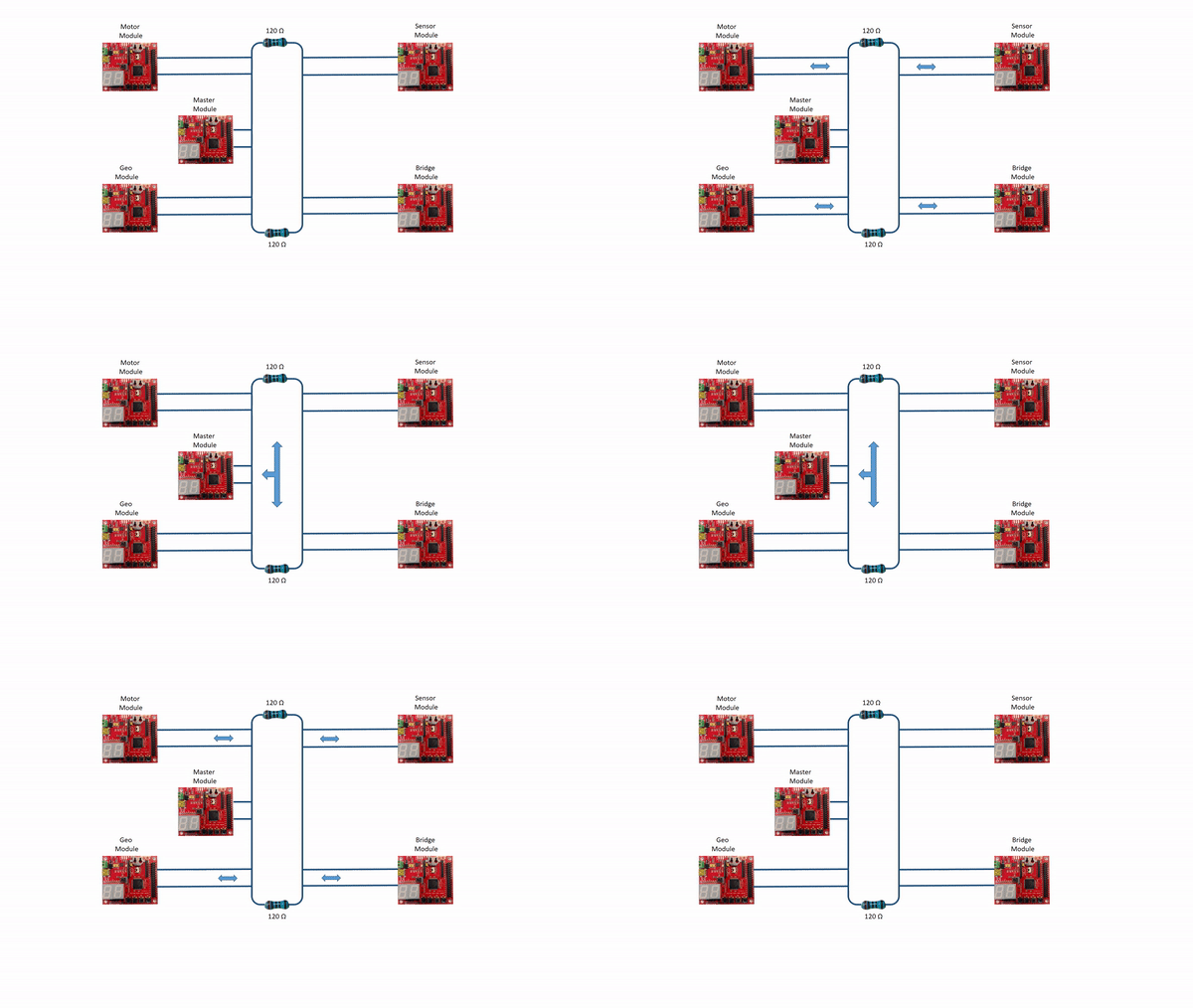
CAN bus will be used as a communication bus between microcontrollers. Can Bus is a broadcast bus where all the controller will be listening to the incoming frames, CAN bus uses frames for data communication. Each module will have its unique ID called MsgID, the system startup is initiated with a START command sent to car from Android application. The path and destination are configured prior to START command. The car will navigate between the checkpoints by taking location feedback through a GPS system and using sensors for obstacles avoidance in the path of the car. IO systems present on the car give us information about the status of the car.
The Objectives of this project are:
- All the modules must communicate with each other over the CAN bus.
- The car must determine and avoid obstacles using LIDAR and ultrasonic sensors.
- The car must interact with a Bluetooth mobile application, obtaining checkpoint and path data.
- Car must be able to speed control based on the terrain.
- The car must be able to gather location using GPS module and route towards the destination.
- Provide module and sensor status using the LCD or LEDs.
- Master must be able to determine the action required by data gathered through sensors and GPS.
Team Members & Responsibilities
- Master Controller
- Shashank Iyer
- Aditya Choudari
- Geographical Controller
- Kalki Kapoor
- Aditya Deshmukh
- Communication Bridge + Android Application + LCD
- Ashish Lele
- Shivam Chauhan
- Venkat Raja
- Motor and I/O Controller
- Aditya Choudari
- Manan Mehta
- Sensor Controller
- Pushpender Singh
- Hugo Quiroz
- Module Level Testing
- Manan Mehta
- Aditya Choudari
Project Schedule
Legend: Motor & I/O Controller , Master Controller , Communication Bridge Controller, Geographical Controller, Sensor Controller , Team Goal
| Week# | Start Date | End Date | Task | Status |
|---|---|---|---|---|
| 1 | 09/12/2017 | 09/19/2017 |
|
Completed |
| 2 | 09/19/2017 | 09/26/2017 |
|
Completed |
| 3 | 09/26/2017 | 10/03/2017 |
|
Completed |
| 4 | 10/03/2017 | 10/10/2017 |
|
Completed |
| 5 | 10/10/2017 | 10/17/2017 |
|
Completed |
| 6 | 10/17/2017 | 10/24/2017 |
|
Completed |
| 7 | 10/24/2017 | 10/31/2017 |
|
Completed |
| 8 | 10/30/2017 | 11/7/2017 |
|
Completed |
| 9 | 11/7/2017 | 11/14/2017 |
|
Completed |
| 10 | 11/14/2017 | 11/21/2017 |
|
Completed |
| 11 | 11/21/2017 | 11/28/2017 |
|
Completed |
| 12 | 11/28/2017 | 12/05/2017 |
|
Completed |
| 13 | 12/05/2017 | 12/12/2017 |
|
Completed |
Parts List & Cost
| Item# | Part Desciption | Vendor | Qty | Cost |
|---|---|---|---|---|
| 1 | RC Car - Traxxas 1/10 Slash 2WD | Amazon | 1 | $189.95 |
| 2 | Traxxas 2872X 5000mAh 11.1V 3S 25C LiPo Battery | Amazon | 1 | $56.99 |
| 3 | Traxxas 7600mAh 7.4V 2-Cell 25C LiPo Battery | Amazon | 1 | $70.99 |
| 4 | Traxxas 2970 EZ-Peak Plus 4-Amp NiMH/LiPo Fast Charger | Amazon | 1 | $35.99 |
| 5 | Bluetooth Module HC-05 | Amazon | 1 | $8.99 |
| 6 | 4D systems 32u LCD | 4D systems | 1 | $73.70 |
| 7 | LV Maxsonar EZ0 Ultrasonic sensors | Robotshop | 5 | $124.75 |
| 8 | LIDAR Sensor | Robotshop | 1 | $190 |
| 9 | Ultimate GPS breakout | Adafruit | 1 | $49.95 |
| 10 | CAN tranceivers | Microchip Samples | 10 | Free |
| 11 | SJOne Boards | Provided by Preet | 5 | $400.0 |
DBC File Link
Link to the DBC file which defines the CAN communication of the system
DBC link on GitLab
Sensor Controller
Design & Implementation
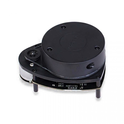
Sensor controller is responsible for Obstacle Detection. This project is designed to use two sensor components, LIDAR, which is the state of the art sensing components that are being used by the self-driving car industry to map the objects in the vicinity of the vehicle. The other component is more traditional and tested approach for object detection, Ultrasound sensors. Employing the capabilities of these sensors gives and very robust sensing system for the self-driving car. This also ensures to cover the flaws of each system.
Hardware Design
Discuss your hardware design here. Show detailed schematics, and the interface here.
Hardware Interface
In this section, you can describe how your hardware communicates, such as which BUSes used. You can discuss your driver implementation here, such that the Software Design section is isolated to talk about high-level workings rather than the inner working of your project.
Lidar Sensor
Lidar Sensor is interfaced using a UART Protocol. As shown below the Lidar Sensor sends 5 bytes per data point over UART to the Sensor Controller. These 5 bytes include 1 byte for the quality of data, 2 bytes for the angle of reading, and 2 bytes for the distance of reading. The Sensor Board initiates the Lidar Sensor readings by sending a start command opcode. The Lidar Sensor responds by sending a start scan confirmation followed by continuous data readings.
Ultrasonic Sensor
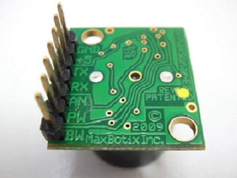
LV‑MaxSonar‑EZ1 ultrasonic sensor by MaxBotix is used for a wide range object detection. Ultrasound sensors are configured as 2 ultrasound sensors in the front and one in the rear as the initial test configuration, this configuration helps to work in conjuncture with Lidar sensor mounted on the center of the car. The final project makes use of one ultrasound sensor that is dedicated for the detection of objects in the front of the car. LV‑MaxSonar‑EZ1 can detect objects from 0 inches to 254 inches, the object detected within 0-6 inches are provided with range information of 6 inches and the resolution is 1 inch. LV‑MaxSonar‑EZ1 provides three output formats pulse width output, analog output, and RS232 serial output. This project is using pulse width as the output from ultrasound sensors.
The following figure shows the pinout of the LV‑MaxSonar‑EZ1 ultrasonic sensor.
Pin Out description
- Pin 1-BW- When BW pin is held high the TX output sends a pulse suitable for low noise chaining.(Not Used)
- Pin 2-PW- This pin outputs a pulse width representation of range. The distance can be calculated using the scale factor of 147uS per inch.
- Pin 3-AN- Outputs analog voltage with a scaling factor of (Vcc/512) per inch.(Not Used).
- Pin 4-RX– This pin is internally pulled high. The LV-MaxSonar-EZ will continually measure range and output if RXdata is left unconnected or held high. If held low the sensor will stop ranging. Bring high for 20uS or more to command a range reading.
- Pin 5-TX- When the *BW is open or held low, the TX output delivers asynchronous serial with an RS232 format.(Not Used)
- Pin 6-+5V- Vcc – Operates on 2.5V - 5.5V. Recommended current capability of 3mA for 5V, and 2mA for 3V. Please reference page 4 for minimum operating voltage versus temperature information. Pin 7-GND- Return for the DC power supply.
- GND- must be ripple and noise free for best operation.
Software Design
Show your software design. For example, if you are designing an MP3 Player, show the tasks that you are using, and what they are doing at a high level. Do not show the details of the code. For example, do not show exact code, but you may show psuedocode and fragments of code. Keep in mind that you are showing DESIGN of your software, not the inner workings of it.
Implementation
This section includes implementation, but again, not the details, just the high level. For example, you can list the steps it takes to communicate over a sensor, or the steps needed to write a page of memory onto SPI Flash. You can include sub-sections for each of your component implementation.
Testing & Technical Challanges
Motor & I/O Controller
The Motor and I/O controller board is responsible for control of the motors and relay information between the LCD and the rest of the System.Hence, the board could be divided into 2 parts, the motor control, and the LCD control. The motor control logic controls the steering and the speed of the vehicle using a servo and DC motor respectively based on the Car Control CAN message from the master. Based on other can messages from the Sensor Board, the Geo Board and the Android Board, the Motor and I/O board processes and communicates the information to the LCD display
Design & Implementation
The Servo and DC motor are controlled via PWM and hence initial work required finding out the required duty cycle values for desired motor frequency. Higher frequency gives us a better resolution and response from the motor but for this project, a frequency of 8Hz was ideal enough to attain the required speed of vehicle and response time of the steering of the vehicle. To find out the PWM values, we connected the RC receiver of the Traxxas Slash 2WD vehicle to an oscilloscope and varied the remote controller for forward and reverse movement as well as right and left movement of the car. PWM signals were observed on the CRO and as the controller trigger was varied, the duty cycle of the PWM signal on the CRO also varied.
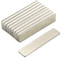
Speed control of the vehicle was carried out using a Traxxas speed sensor and a bunch of magnets. Applying the principles of a hall effect sensor, the magnets were attached to the inside of a wheel and the speed sensor was placed on the shaft of the back wheel. With every rotation, the magnets cut the field of the speed sensor giving a positive voltage to the SJone board. This positive voltage is accounted for and after neceassy calculations, we derive the speed of the vehicle.
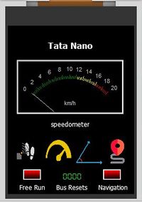
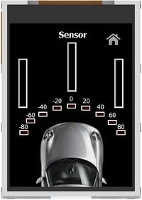
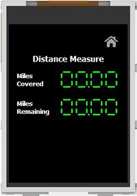
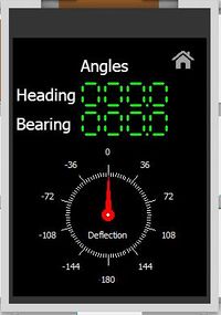
To read data on the fly, LCD display by 4D systems was interfaced. The SJOne board communicates with the LCD display over UART using basic ASCII values that represent commands as well as information. The LCD graphics are preprogrammed into a MicroSD using the 4D systems workshop software and each graphical object consists of ASCII commands to control it.
Hardware Design
The Motor and I/O controller system consists of the following modules to perform various functions as mentioned in the description section of the table
| S.No | Name | Description |
|---|---|---|
| 1. | SJOne | Controller board with GPIO and PWM pins to control rest of the interfaces |
| 2. | ESC / DC motor | Controls speed of vehicle |
| 3. | Servo Motor | Controls direction of vehicle |
| 4. | Traxxas Speed sensor and magnets | Senses rotation of motor/wheel of vehicle for speed control |
| 5. | LCD | Displays vital information about the vehicle |
Hardware Interface
Electronic Speed Controller (ESC)
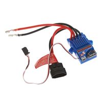
The ESC is the interface between the DC motor and SJOne board. The ESC enables speed control, protects the rest of the system from any back EMF and allows configuration of the motors in various Modes (Training/Race/Sport). The ESC has 2 connectors the first one is a 2 wire connector, black and red which is connected to the LiPo battery that powers the motors and the second if a connector of 3 wires. 2 wires (black and red) supply a 7V DC power stepped down from the 11V lipo battery to the motors. This 7V power is used to control the servo motor using the power distribution board designed for this project. The 3rd wire (white) is a PWM input signal to the ESC from the SJOne controller that defines the speed of the motor.The ESC consists of a button to calibrate and turn on/off the ESC located on it.The ESC can be calibrated by following the steps mentioned on the Traxxas website
| S.No | Wires - ESC | Description | Wire Color Code |
|---|---|---|---|
| 1. | Positive wire (already Connected) | Connects to DC Motor positive | RED |
| 2. | Negative wire (already Connected) | Connects to DC Motor negative | BLACK |
| 3. | Positive Supply | Connects to supply of Li-Po battery | RED |
| 4. | Ground Wire | Connects to ground of Li-Po battery | BLACK |
| 5. | PWM input connected to P2.1 | PWM Signal From SJOne | WHITE |
| 6. | Servo Vcc Supply | 7V power supply to power the servo | RED |
| 7. | Common Ground | Negative terminal | BLACK |
DC Motor
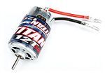
The speed and direction of rotation of the motor (forward/backward) are controlled by the direction and amount of current that is supplied to the DC motor. In the figure below you can see the motor has 2 wires; one for positive(Red) and one for negative(Black). For the forward movement of the wheels the current flows from positive to negative, and for the reverse movement, the current flows from negative to positive. The speed is controlled by the amount of current it is fed from the ESC which is in turn controlled by the duty cycle of its PWM signal input.
| S.No | Wires - DC Motor | Description | Wire Color Code |
|---|---|---|---|
| 1. | Positive Wire (already Connected) | Positive Terminal | RED |
| 2. | Negative Wire (already Connected) | Negative terminal | BLACK |
Servo Motor
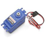
The direction the vehicle's front wheels turn is dependent on the servo motor in the vehicle. Based on various PWM signals, the servo steers the front wheels of the vehicle in the left and right direction. The servo has 3 wires of which one is for the PWM input signal whereas the other two are to power up the servo. We powered our servo motor using the 6v power supply from the battery elimination circuit present in the ESC so that a single switch to turn on and off both the servo and DC motor.
| S.No | Wires - Servo Motor | Function | Wire Color Code |
|---|---|---|---|
| 1. | PWM connected to P2.2 | PWM signal from SJOne board | WHITE |
| 2. | VCC | 5 volts | RED |
| 3. | Ground | Common ground to system | BLACK |
Speed Sensor
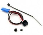
To maintain the speed of the vehicle, a speed sensor from Traxxas was used. The assembly provided a single magnet and required mounting the sensor in the rear compartment. This setup had a major drawback of using just one magnet. One magnet did not provide enough resolution for the speed check algorithm at low speeds and small distances. Hence, we opted to mount the speed sensor on the motor shaft and attached 4 magnets on the wheel. The sensor works on the hall effect principle where it provides a current across its terminal when it is close enough to a magnet. These pulses are read by the SJOne board and fed to the speed control algorithm. the speed sensor has 3 wires, the white where are the output wire that provides the pulses to the SJone board and the other wires power the sensor.
| S.No | Wires - Speed Sensor | Function | Wire Color Code |
|---|---|---|---|
| 1. | Signal wire connected to P2.5 | Ouput GPIO that supplies pluses | WHITE |
| 2. | VCC | Input 5v supply | RED |
| 3. | GND | Common ground | BLACK |
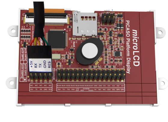
uLCD32-PTU
uLCD32-PTU by 4D systems has a 3.2" TFT LCD Display module. The module comes with a display resolution of 240x320 pixels. 4D Systems provides a programming cable based on UART for burning the LCD code to the module. The project is burnt to a uSD card which is used for display during booting of the LCD.
The following figure shows the programming cable and the pins of uLCD32-PTU.
Software Design
Motor and IO Controller
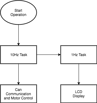
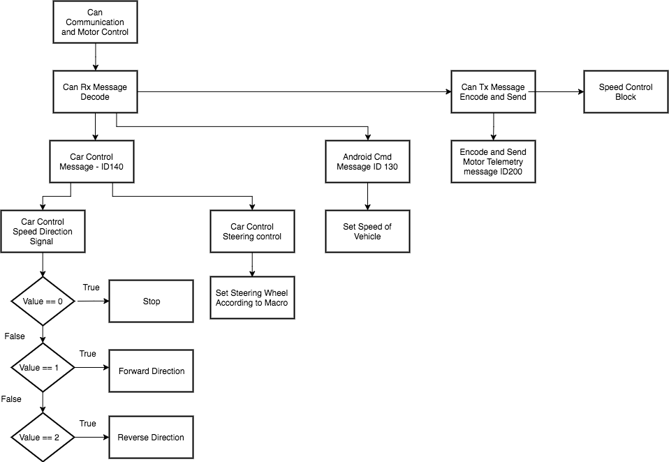
The motor Control logic controls the steering and speed of the vehicle by controlling the ESC and servo motor. The motor control algorithm runs in the 10Hz periodic scheduler to provide a quick response at 100ms. That is, the motor algorithm is executed and responds every 100ms.
The speed control algorithm used to maintain speed is also executed in the 10Hz task so it can update the PWM of the vehicle every 100ms to quickly adjust the speed during down hill and up hill or rough terrains
DC Motor and Servo Motor
The steering and speed algorithm generates 2 PWM signals to the module at 10Hz each. The input to the steering and speed algorithm consists of can messages from the Master which decodes into steering and speed commands.
The steering and speed commands are macros we defined that represent PWM interms of duty cycle that controls the servo and DC motor. CMPE243 F17 nano MotorSW10hz.png
LCD DISPLAY
uLCD-32PTU communicates with the SJ1 board over UART. The steps taken for interfacing the LCD display with the SJ1 board are listed below:
- Creating a project using Workshop 4 IDE and programming the LCD display
- After finalizing the design of the LCD's layout, a genie project was created using Workshop 4.
- The layout was split into different forms (pages) and appropriate buttons and gauges were added for display.
- uLCD-32PTU was programmed with the help of programming cable provided by 4D systems.
- Programming SJ1 Board for LCD Display
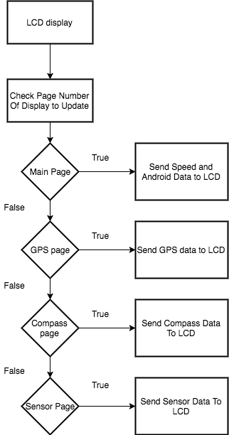
- As raw data often cannot be displayed on the LCD directly, the values to be displayed had to be converted to appropriate byte-sized values.
- Communication with SJ1 board was established at the baud rate of 115200 bps.
- Commands for writing data and reading acknowledgment for various gauges were coded in the SJ1 board.
Implementation
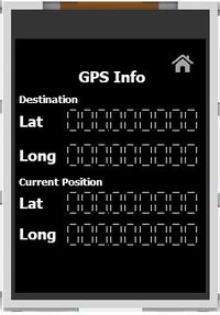
LCD screens
Testing & Technical Challanges
A major challenge that was faced while interfacing the LCD with the SJ1 board was that the SJ1 board was frequently getting rebooted while sending data for all metrics at once. To counteract this problem, the metrics were split into different forms(pages) for display and the data belonging to the active form alone was sent. Another challenge was that LCD does not support display of data that is more than 4 digits in length. To support display of data such as GPS coordinates, multiple 4 digit display objects had to be used with data manipulation before sending over UART.
Geographical Controller
Geographical Controller is one the most important controller in the car which help it to navigate to its destination.
Design & Implementation
Hardware Design
Hardware Interface
Software Design
Implementation
Testing & Technical Challanges
Communication Bridge Controller
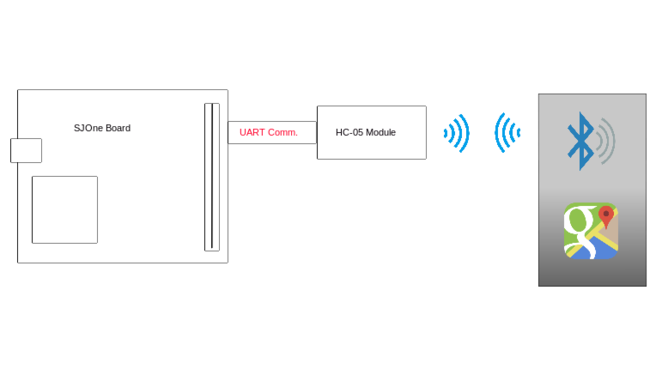
This is a part of a project where different technologies meet. To make our project more understandable and easily accessible, we need some kind of user interface. Where a user or customer of the product can interact with the product easily and without knowing the technical complexity of it. We have decided to make an android application which communicates with the car and can show its current location, speed, heading direction etc. Here, we have discussed the design and implementation.
Design & Implementation
Main purpose of this is to exchange data using some wireless communication protocol. We had options like WiFi (UART to WiFi converter) or Bluetooth (UART to bluetooth converter). Here we made decision based on actual requirement and usability of that communication protocol. In case of WiFi it has advantages like long range, high speed and robust communication without loosing data packets. It can also connect to multiple devices at same time. Now, the actual requirement is to show useful data to user, where use is sitting inside a car(idle situation). Which doesn't require long range and multiple receivers like WiFi provides. So, we moved ahead with bluetooth which works fine and delivers everything we wanted.
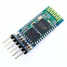
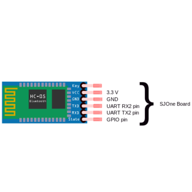
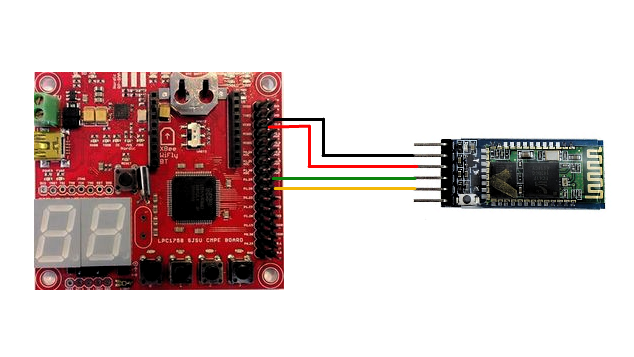
we chose HC-05 module. It is a serial to Bluetooth converter with a very compact hardware design. On the other end, to make an android application we chose android studio, which is freely available by Google. It is a very intelligent software which helps programmer or developer like us who has little or no knowledge of java programming language, to develop a good piece of code with high code readability and re-usability.
Hardware Design
Hardware Interface
Software Design
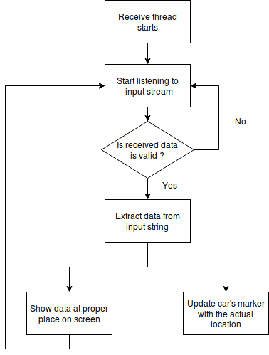
Here, we will discuss the software design approach for communication bridge. As discussed in earlier topics, this communication is bridge is to send and receive data asynchronously to the main processes running over car end or mobile end. Let's make the idea clear what exactly we need to send and receive over bluetooth and when do we need to do that communication. As Preet asked all the teams to connect to car without pressing any button. It should automatically discover the car and be connected. When it comes to the data, we want to send start and stop commands and application expects important sensor data to display to user. Software design is divided into 2 parts,
- Android application
- Micro-controller end with HC-05.
Android application
Android application is developed using Android Studio free software from Google. The application structure is divided into 2 sections. First to use mobile bluetooth APIs to connect with the car and second is to show car's actual position on Google Maps. Let's talk about this in details.
- Homepage (Main activity):
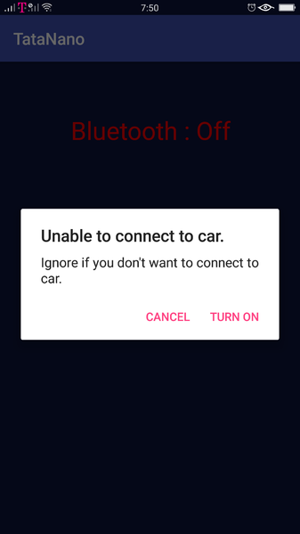
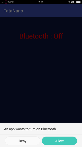
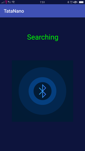
In android application development every page on screen is called activity. Here homepage is named as main activity. In this activity we check for present bluetooth status to decide, whether application should start searching for car or not. If not turn on the bluetooth facility. Make sure that we have provided the application bluetooth permission which building the application. It starts searching for discoverable bluetooth devices around the mobile device. It particularly looks for MAC id of the found device. If it matches with the desired MAC id, it proceeds and tries to create the bluetooth socket. Meanwhile it shows on screen, if it found a new device or connecting to a device or connected to car. If user turns of the bluetooth facility manually from slide-down menu, it handles that situation gracefully and asks if user really want to turn it off or it should retry. After successful connection creation, it helps user to navigate to next activity to get command over car.
- Google Maps (Maps activity):
When user reaches this activity, it is assumed that connection was successfully established. Here, google maps API works in background to load the map from internet. To use their resource, Google wants us to have an activated key. Which has 2 versions, first is debug key and another is release key. As name suggests debug key is for testing and debugging purpose, where release key is for final version. After map is ready, as assuming that connection is still alive, application presents input buttons for user to take command over the car. Google APIs are very easy to use and understand. To give the checkpoints and destination to the car we used an API which gives location of the point we tap on screen. Thus, by tapping on screen we create a list of checkpoints which later be shared with the car with start command.
When user gives start command, he also has to specify a desired speed for car. Valid input for speed is from 0 to 10 miles per hour. Values other than this is fixed to the nearest end values of speed range (0 or 10). But there is an exception in speed. If user wants to test the car which we call free run, speed input for that is 55. 55 as a speed tells car to free run and there is no destination. Flow chart shown here explains the work.
Micro-controller end
Implementation
Testing & Technical Challenges
Android application
- Establishing connection: When application building was in initial stage, we were trying to connect any random devices to check the capability of our code. We were able to connect with some devices, but other were either taking too long or rejecting the bluetooth connection request. Later then we focused on only one device HC-05 which we were using on car. It is working well for that.
- Application compatible to all: I figured out that even when we have given list of permissions to application, phone sometime doesn't allow random application to use resources for security purpose. Like in our case, application was connecting to the car perfectly but in maps activity, map wasn't showing user's own location. Which tracked down to the point that we need to go in application settings and give permission for GPS, network and fine location. Then it worked well for multiple devices. There should be some extra steps in application from developer, which forces user to give permission if not given automatically.
- Extra code: Initially to get the list of previously paired devices, we had written a function. Now, in a scenario where car is not around, and we try to connect to it, this function was always returning true as it found the car's device in paired devices list and tried to connect it. As connecting to a device is a blocking event, application freezes for a moment if not written in thread, our function was always getting stuck there and successful connection ratio was 10% of all the attempts as 90% of the time it got device in paired device list and tried connecting to it. Then we always looked around by keeping mobile in discovery mode. If it finds a device with matching MAC address, then it tries to connect.
- Debug key for Google maps: Debug key is a permission from google to use their maps service for free but only for debugging purposes. If we share the apk with debug key, maps will show up blank on screen. While working on android code with the teammate, I figured out that debug key generated by my friend, wasn't working for me (blank map), but release key worked fine. I haven't got the solution for this yet but I believe it is because the machines we use. Google takes some machine information to keep track who is using their services. I may try generating new debug key from my machine and test.
Micro-controller end in freeRTOS
Master Controller
Design & Implementation
Hardware Design
Hardware Interface
Software Design
Implementation
Testing & Technical Challanges
Testing & Technical Challenges
Describe the challenges of your project. What advise would you give yourself or someone else if your project can be started from scratch again? Make a smooth transition to testing section and described what it took to test your project.
Include sub-sections that list out a problem and solution, such as:
Conclusion
Conclude your project here. You can recap your testing and problems. You should address the "so what" part here to indicate what you ultimately learnt from this project. How has this project increased your knowledge?
Project Video
Upload a video of your project and post the link here.
Project Source Code
References
Acknowledgement
Any acknowledgement that you may wish to provide can be included here.
References Used
- uLCD 32 PTU datasheet http://www.4dsystems.com.au/productpages/uLCD-32PTU/downloads/uLCD-32PTU_datasheet_R_2_1.pdf
- Workshop 4 user guide http://www.4dsystems.com.au/productpages/4D-Workshop-4-IDE/downloads/Workshop-4_userguide_R_2_1.pdf
Appendix
You can list the references you used.
