Difference between revisions of "S17: Sphero Droid"
Proj user11 (talk | contribs) (→Team Members & Responsibilities) |
Proj user11 (talk | contribs) (→Team Members & Responsibilities) |
||
| Line 38: | Line 38: | ||
** SDCard<br> | ** SDCard<br> | ||
** Wiki page reporting<br> | ** Wiki page reporting<br> | ||
| − | ** Code integration[ | + | ** Code integration[Gps and Sdcard card tasks]<br> |
* <font color="red"> [https://www.linkedin.com/in/naveenbr/ Naveen Kumar Bhuthakatanahalli Ramalingaiah] | * <font color="red"> [https://www.linkedin.com/in/naveenbr/ Naveen Kumar Bhuthakatanahalli Ramalingaiah] | ||
** SDCard<br> | ** SDCard<br> | ||
Revision as of 03:39, 25 May 2017
Contents
- 1 Grading Criteria
- 2 Sphero Droid
- 3 Abstract
- 4 Objectives & Introduction
- 5 Schedule
- 6 Parts List & Cost
- 7 Design and Implementation
- 8 Testing & Technical Challenges
- 9 Conclusion
- 10 References
Grading Criteria
- How well is Software & Hardware Design described?
- How well can this report be used to reproduce this project?
- Code Quality
- Overall Report Quality:
- Software Block Diagrams
- Hardware Block Diagrams
- Schematic Quality
- Quality of technical challenges and solutions adopted.
Sphero Droid
Abstract
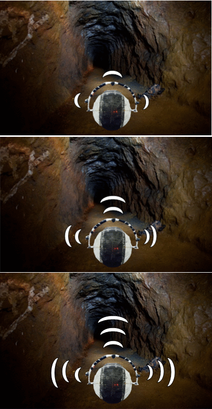
Robots are revolutionizing almost every industry, primarily in the sectors where human safety is at risk. In hazardous working conditions such as in the mining industry, the lack of knowledge about the geographic nature and the environmental conditions of the mine hinder the rescue operations. Autonomous robots are being employed to improve the plight of mine workers and rescue operators. The robotic vehicle can explore the inaccessible and unworkable mines and disaster-affected areas and send valuable information to the teams to assist in search and rescue operations. But traditional robots could be rendered useless if they are overturned or in terrains having staircases and ledges. Also, there is a possibility of failure of the electrical and mechanical components exposed to the harsh environmental conditions. An autonomous spherical robot is a better option since its shape offers better robustness and rigidity. The spherical robot will enclose all the components within it and will not have any wheels or legs on its exterior. This feature enables it to operate in any hazardous conditions since there will be very less chance for the components to get damaged by the surrounding environment. The spherical design allows it to easily maneuver in different types of terrain, be it stairs or corners, and have no risk of being overturned. These advantages enable the robot for many applications such as exploration and mapping of access routes, surveillance and rescue operations in uncomfortable working conditions.
Objectives & Introduction
The objective of this project is to design an autonomous spherical robot with sensors, Global Positioning System (GPS) module, Bluetooth module and other control units interfaced to the microcontroller, which navigates its way to the destination avoiding obstacles. The temperature and the route followed by the robot can be logged on the SD card. These features enable the robot for many applications such as exploration and mapping of access routes, surveillance, and rescue operations in uncomfortable working conditions.
Team Members & Responsibilities
- Harshitha Bura
- GPS and Temperature Sensor
- SDCard
- Wiki page reporting
- Code integration[Gps and Sdcard card tasks]
- GPS and Temperature Sensor
- Naveen Kumar Bhuthakatanahalli Ramalingaiah
- SDCard
- Bluetooth module and Android Aplication
- Code integration[Andriod task integration with overall Freertos tasks]
- Hardware design and implementation
- SDCard
- Shivam Chauhan
- PCB Designing
- Servo Motor
- Ultrasonic Range Finders
- Hardware design and implementation
- Code integration[Overall Freertos tasks]
- PCB Designing
- Sushma Nagaraj
- Servo Motor
- Ultrasonic Range Finders
- Wiki page reporting
- Code integration[Servo,DC motor and Sensor tasks]
- Servo Motor
- Virginia Menezes
- DC Motors
- Wiki page reporting
- Code integration[Servo and DC motor tasks]
- DC Motors
Schedule
| Week# | Start Date | End Date | Task | Status | Actual Completion Date | |
|---|---|---|---|---|---|---|
| 1 | 3/21 | 3/27 |
|
Done | 3/29 | |
| 2 | 3/28 | 4/3 |
|
Done | 4/9 | |
| 3 | 4/9 | 4/18 |
|
Done | 4/21 | |
| 4 | 4/18 | 4/25 |
|
Done | 4/28 | |
| 5 | 4/25 | 5/2 |
|
Done | 5/7 | |
| 6 | 5/2 | 5/9 |
|
In Progress | ||
| 7 | 5/9 | 5/20 |
|
Plan | ||
| 8 | 5/16 | 5/23 |
|
Plan |
Parts List & Cost
| Qty | Description | Manufacturer | Part Number | Cost | Links |
|---|---|---|---|---|---|
| 1 | SJ One Board [1] | Preet | SJ-one | $80 | http://www.socialledge.com/sjsu/index.php?title=SJ_One_Board |
| 2 | DC Motor | RobotShop | Pololu 4.5V, 80rpm Right Angle Plastic Gear Motor | $4.95 | http://www.robotshop.com/en/pololu-80rpm-right-angle-plastic-gear-motor.html |
| 1 | Servo Motor | Fry's electronics | Metal Gear Digital Servo Part No. LS-0009AF | $19.99 | http://www.frys.com/product/7027281 |
| 1 | Motor Driver | Fry's electronics | Motor Driver | $9.99 | http://www.frys.com/product/8353697 |
| 1 | GPS Logger | Spark fun Electronics | Venus638FLPx | $59.95 | https://www.sparkfun.com/products/10920 |
| 1 | Bluetooth Module | Amazon.com | HC-05 Bluetooth | $8.49 | https://www.amazon.com/dp/B01G9KSAF6?psc=1 |
| 3 | Ultrasonic sensor | Amazon.com | LV Maxsonar -EZ MB1010 | $74.85 | https://www.amazon.com/Maxbotix-MB1010-LV-MaxSonar-EZ1-Range-Finder/dp/B00A7YGVJI |
| 1 | Antenna GPS Embedded SMA | Spark fun Electronics | VTorch Datasheet | $11.95 | https://www.sparkfun.com/products/177 |
| 1 | PCB components | Amazon.com | (7805, 2 pin SPDT switch, 4004 diode, LD1117, Female pin header, male pin header, USB type B female jack, DC power jack, power supply module) | $72.00 | https://www.amazon.com/gp/product/B01LRXIJRY/ref=oh_aui_detailpage_o03_s02?ie=UTF8&psc=1 |
| 2 | Wheels | Amazon.com | 70 x 8mm Black Robot Wheels | $12.00 | https://www.amazon.com/gp/product/B00T3MQDHU/ref=oh_aui_detailpage_o08_s00?ie=UTF8&psc=1 |
| 2 | Bearing | Amazon.com | 2 Pcs 22mm Outside Dia Plastic Coated Ball | $7.93 | https://www.amazon.com/gp/product/B00HR5SJKE/ref=oh_aui_detailpage_o08_s01?ie=UTF8&psc=1 |
| 1 | Hollow spherical ball | Amazon.com | Giant Chinchilla Run-About 11-1/2-Inch Exercise Ball | $15.76 | https://www.amazon.com/gp/product/B0006IK0LA/ref=oh_aui_detailpage_o00_s00?ie=UTF8&psc=1 |
Design and Implementation
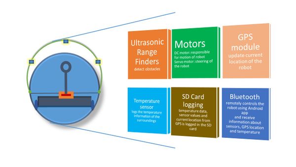
System Block diagram
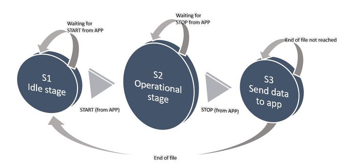
System State Diagram
Hardware Design
We have four distinct hardware modules used in this project:
- Ultrasonic Range Finders (sensors)
- Motors
- GPS Module
- Bluetooth Module
Ultrasonic Range Finders
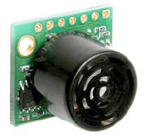
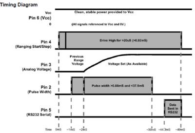
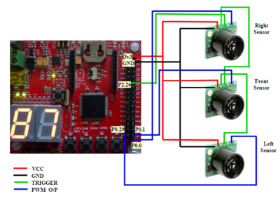
Used MB1010 LV-MaxSonar-EZ21 Ultrasonic Rangefinder sonar sensors, which can from 6-inches to 254-inches, with 1-inch resolution. Any object from 0-inches to 6-inches is typically ranged as 6-inches. They are used in PW mode for outputting. For efficient working of sensors without any crosstalk, we have configured 3 sensors in the chaining mode called AN output commanded loop. This mode of configuration uses 5 pins of each sensors such as VCC = +5V,GND,TX,RX and PWM. While triggering,the first sensor RX pin is held high for a time period > 20micro seconds and < than 48ms.This will start the sensor chain. The first sensor will range, then trigger the second sensor to range and so on for all the sensor in the array.
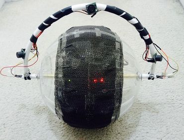
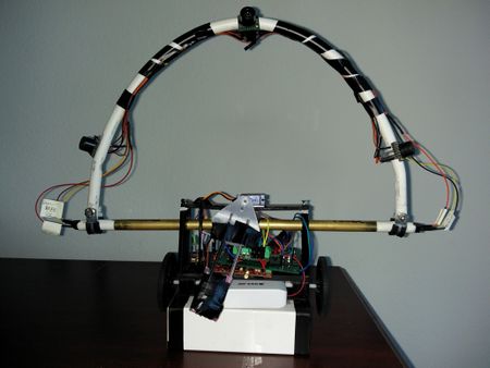
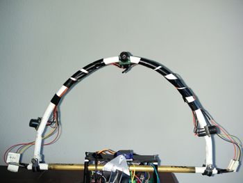
Mounting of the sensors are made on a curved platform such that the sensors are aimed with a positive slope and not horizontally. This decision is made in order to avoid interference with the ground due to the wide range of detection by the sensors.
Motors
- DC Motors
The DC motors used in the project are 100 RPM low-cost single shaft straight geared motors. They are suitable for lightweight robots that do not require high power or torque.
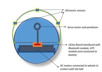
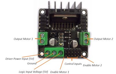
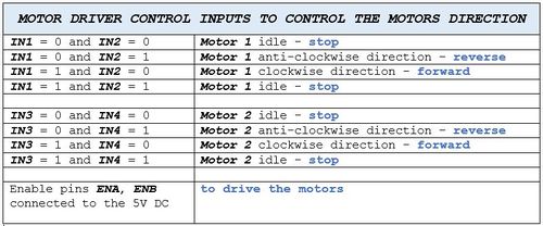
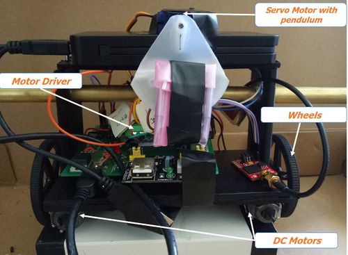
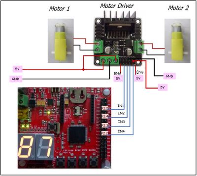
The DC motors are connected to the wheels which are in contact with the base of the ball. The DC motors are driven by a driver module which controls the motor direction and speed.
- Servo Motors
Write about the servo motor used and its uses.
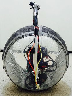
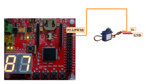
The hardware implementation of how the DC motors are connected to the wheels which are driven from the SJOne board and how the servo motor is connected with the pendulum to steer the robot in right or left direction can be viewed in the figure below.
Bluetooth Module
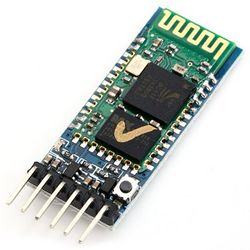
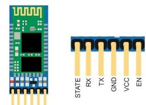
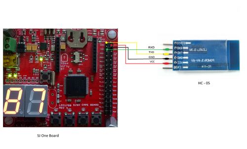
Bluetooth module HC-05 is used to communicate between the spherical robot and mobile application. It is implemented to establish the connection between the two so that we can remotely control the robot (to send start and stop signals) and receive the data from the robot directly on the Android application. The data being sent by the robot is current GPS location, ultrasonic range sensor values, and temperature sensor values.
Hardware Interface
We have four major hardware modules interfaced with a single SJOne board using different communication protocols. For simplicity sake, we have given a description of how each module is individually interfaced with the SJOne board. In reality, all these modules are connected to a single SJOne microcontroller.
Ultrasonic Range Finders
The ultrasonic range finders have been interfaced with the SJOne board using PWM. How is it triggered??
Motors
The DC motor is connected with the SJOne board via the motor driver module using GPIO. The GPIO signals from SJOne board provide inputs to the motor driver module, which in turn drives the DC motors in forward or reverse direction or stop signal. Servo motor is interfaced with the SJOne board using PWM.
GPS Module
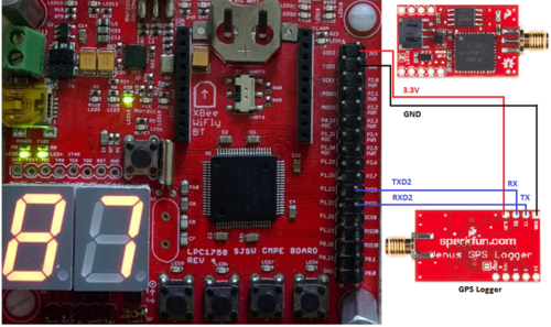
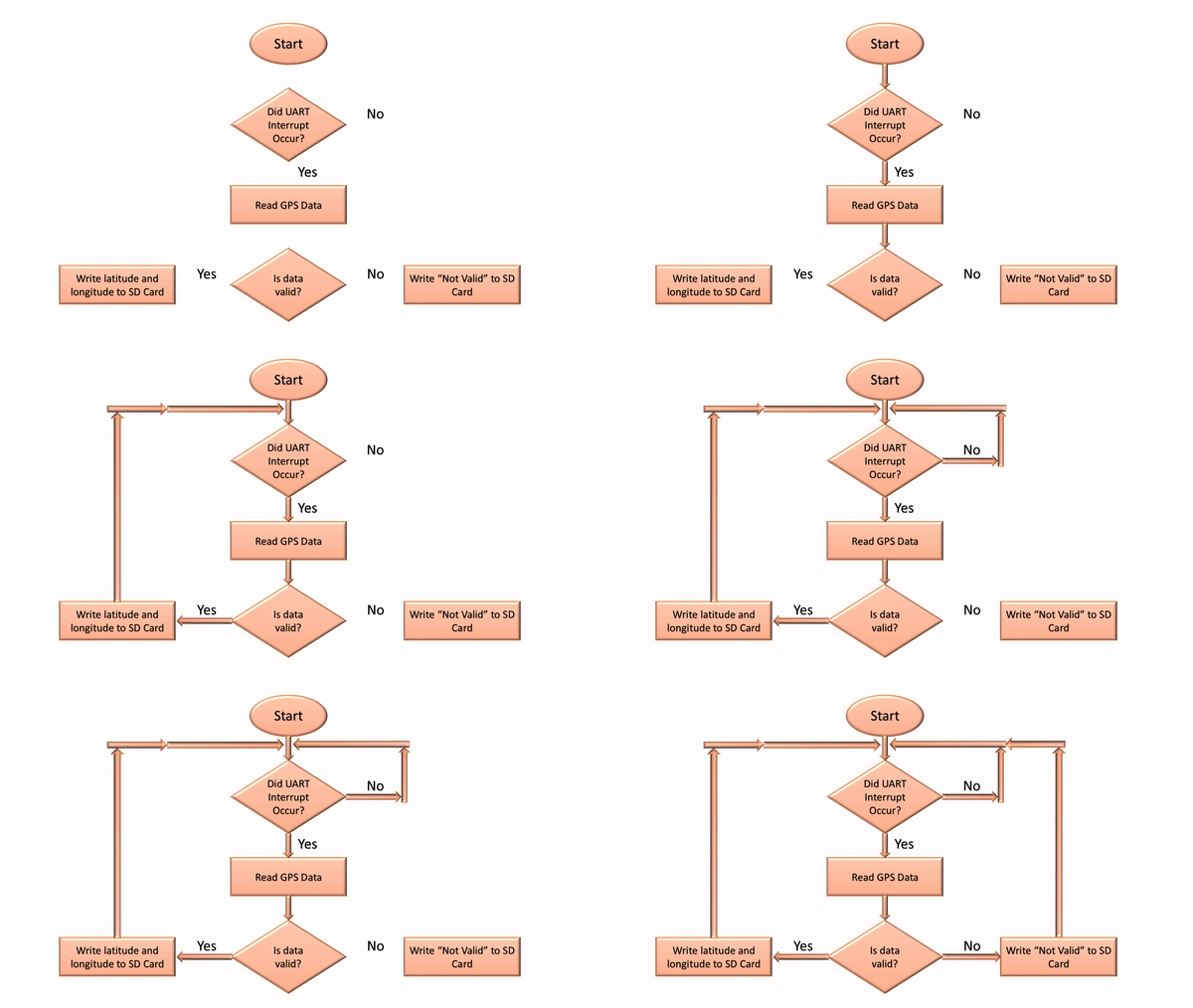
GPS module communicates with SJOne board via UART communication.
Bluetooth module
The Bluetooth HC-05 module is connected with the SJOne board via UART communication.
Software Design
Ultrasonic Range Finder and Motors
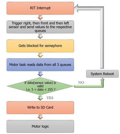
The motors working depends on the input values of sensors (ultrasonic range finders). Depending on whether the sensors can detect an obstacle in its path, the motors continue to run in the forward direction or the servo motor steers the robot towards right or left. The diagrams below shows the algorithm of the logic behind it.
GPS module
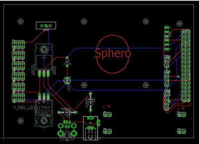
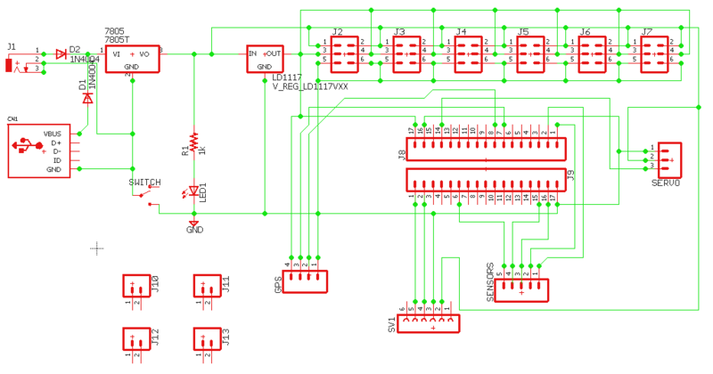
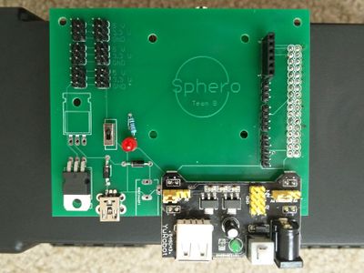
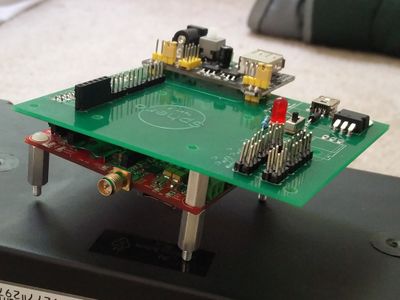
PCB Design
| } |
SD Card Writing
Android Application
Testing & Technical Challenges
Describe the challenges of your project. What advise would you give yourself or someone else if your project can be started from scratch again? Make a smooth transition to testing section and described what it took to test your project.
Include sub-sections that list out a problem and solution, such as:
My Issue #1
Discuss the issue and resolution.
Conclusion
Conclude your project here. You can recap your testing and problems. You should address the "so what" part here to indicate what you ultimately learnt from this project. How has this project increased your knowledge?
Project Video
Upload a video of your project and post the link here.
Project Source Code
References
Acknowledgement
Any acknowledgement that you may wish to provide can be included here.
References Used
List any references used in project.
Appendix
You can list the references you used.
