Difference between revisions of "S13: Solar Panel Tracker"
(→Software Design) |
(→Light-sensing Task) |
||
| Line 285: | Line 285: | ||
[[File:146changeDirectionCodeSnippet.png |center|frame]] | [[File:146changeDirectionCodeSnippet.png |center|frame]] | ||
==== Light-sensing Task ==== | ==== Light-sensing Task ==== | ||
| − | The Light-sensing task was very simple. To keep it this way, all of the 'heavy lifting' was completed in lower level code in the <i>LightSensors.cpp</i> file. Therefore, the only | + | The Light-sensing task was very simple. To keep it this way, all of the 'heavy lifting' was completed in lower level code in the <i>LightSensors.cpp</i> file. Therefore, the only function that the Light-sensing task needs to use is the <i>getDirection()</i> function. However, there is a small amount of code to prevent the degree values from going out of range (0-180 degrees). The task reads the <i>getDirection()</i> values for both the top and base servo motors, which have valid values of negative five (-5), zero (0), or positive five (5). These values are added to the current positional value to obtain updated values to pass to the Servo Motor task through the Queue. |
==== Servo Task ==== | ==== Servo Task ==== | ||
Revision as of 03:39, 22 May 2013
Contents
Grading Criteria
- How well is Software & Hardware Design described?
- How well can this report be used to reproduce this project?
- Code Quality
- Overall Report Quality:
- Software Block Diagrams
- Hardware Block Diagrams
- Schematic Quality
- Quality of technical challenges and solutions adopted.
Project Title
Abstract
The objective of this project is to create a solar panel that tracks the sun. The project will consist of two stepper motors that control the position of the solar panels by using the photo resistors to detect the sun location.
Objectives & Introduction
Solar Panel Sun tracker uses the inputted voltage from photo resistors in order to adjust the position of the solar panel. The project uses and Analog to digital converter. The servo motors are controlled using a pulse; this controls the position of various angles. The servo uses in this project is a standard servo which can only position between 0 and 180 degrees.
The project required the following objectives to be accomplished:
- Read the voltage from photo resistors
- Control servo to move from 0 to 180 degrees
- Compute the location which has the greatest light intensity
- Determine algorithm to convert digital value into servo position
Team Members & Responsibilities
- Arturo Montoya
- Light Sensors (PWM driver) , Servo motor(ADC driver) , and Matrix (Spi driver)
- Matthew Balhorn
- FreeRTOS Software Design
Schedule
| Week | Planned Tasks | Status |
|---|---|---|
| 1 |
|
|
| 2 |
|
|
| 3 |
|
|
| 4 |
|
|
| 5 |
|
|
| 6 |
|
|
Parts List & Cost
| Part | Quuantity | Cost | Link |
|---|---|---|---|
| LPC 1758 SJSU Dev Board | 1 | $60 | |
| 180 Degree Servo | 2 | $25 | |
| Solar Panel | 1 | $15 | |
| LED Matrix | 1 | $25 | |
| Resistors | 4 | $.25 | |
| Photoresistors | 4 | $1.50 | |
| Jumper wires(x50) | 1 | $15 | |
| Servo belt | 2 | $2 | |
Design & Implementation
The design section can go over your hardware and software design. Organize this section using sub-sections that go over your design and implementation.
Hardware Design
Light Sensor
The Solar Panel Sun Tracker consists of the following hardware:
- Resistors
- Photo resistors
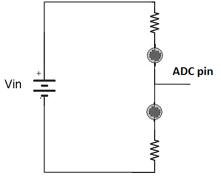
This section is responsible for interpreting the voltage of the photo resistors. The diagram below shows the circuit needed in order to get a voltage division of the two photo resistors. This voltage divider consists of two resistors on each side of the voltage divider output (ADC pin). When the top photo resistor has a greater resistance then the bottom resistor the voltage output will drop. When they both have the same resistance will hold in the middle.
Servo Motor
The servo section consists of the following hardware:
- Servo Motors / Servo Belts
- Solar Panel
This section is responsible for positioning the solar panels perpendicular to the light source. The panel is mounted to a frame that pivots according to the top servo. In order to perform a full scan the top servo motor was mounted on pivoting bases that is controlled by the second motor. The diagram below describes the complete setup in order to properly track the sun from sun rise to sun set.
Hardware Interface
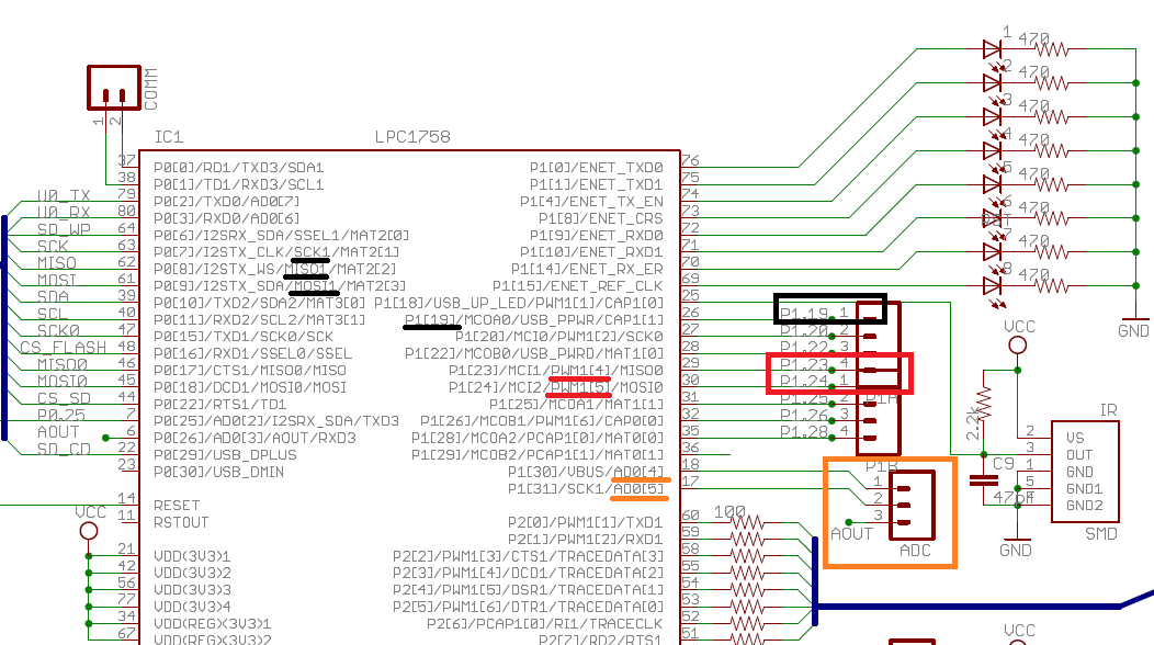
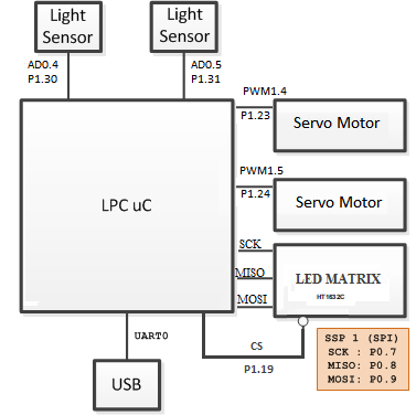
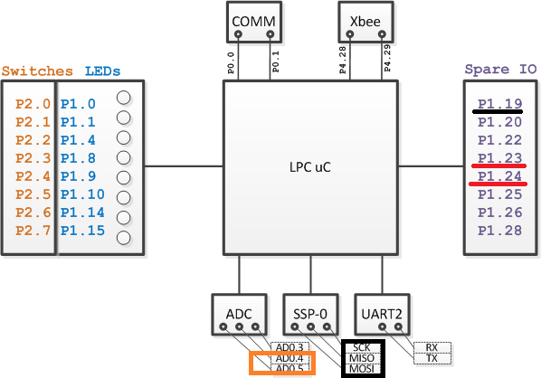
| SJSU Dev Board Pin | Destination Pin | Description |
|---|---|---|
| PWM1.4(p1.23) | Servo Base Control | Set pivot |
| PWM1.5(p1.24) | Servo Top Control | Set pivot |
| AD0.4(p1.30) | Light Sensor Base | Analog Input |
| AD0.5(p1.31) | Light Sensor Top | Analog Input |
PWM
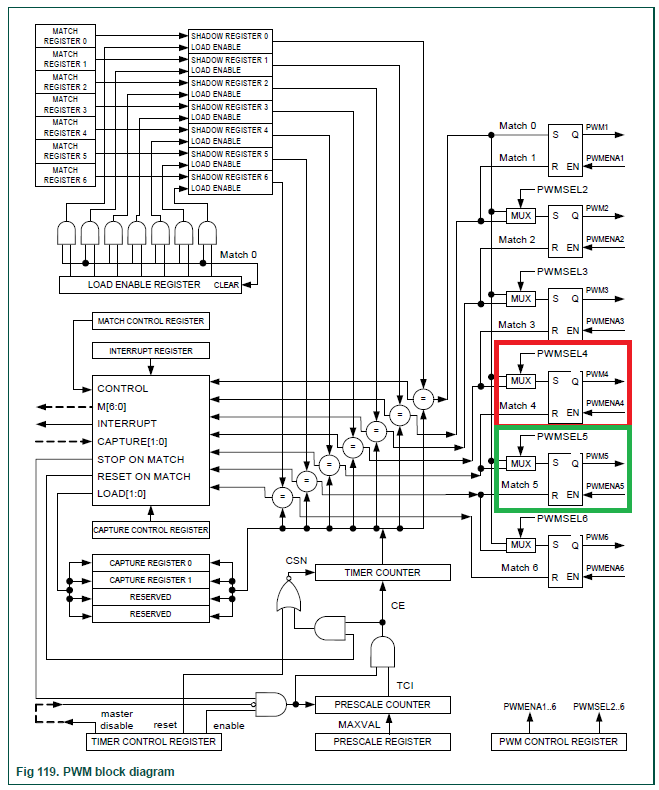
PWM, or Pulse Width Modulation, was used to control the two 180 degree positional servos. The servos required a 50 Hz (20 ms) duty cycle, and the duration of the high duty cycle (in milliseconds) would control the position to move to. Typically, the valid high duty cycles are between 1.0 and 2.0 milliseconds, with 1.0 representing '0 degrees', 1.5 representing '90 degrees' and 2.0 representing '180 degrees.' However, we found that the valid duty cycle range was larger, ranging from [INSERT FULL RANGE]. Knowing this, we expanded the range of the duty cycle and converted the range into a degree range with the change_direction_with_Degree() function. The servos were connected to a 5V power supply and were controlled by PWM1-4(P1.23)and PWM1-5(P1.24).
ADC
Software Design
Show your software design. For example, if you are designing an MP3 Player, show the tasks that you are using, and what they are doing at a high level. Do not show the details of the code. For example, do not show exact code, but you may show psuedocode and fragments of code. Keep in mind that you are showing DESIGN of your software, not the inner workings of it.
Implementation
This section includes implementation, but again, not the details, just the high level. For example, you can list the steps it takes to communicate over a sensor, or the steps needed to write a page of memory onto SPI Flash. You can include sub-sections for each of your component implementation.
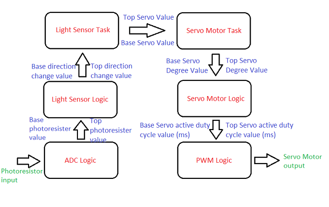
Light sensor Logic
The LightSensors.cpp file contains the functions that the Light-sensing task calls. These functions are getDirection(), which reads the referenced Analog-to-Digital Converter pin (ADC-4 or ADC-5), and returns a value which is the new change in direction for the respective servo motor (Top or Base). The getDirection() function reads the ADC pin value and uses it to decide which direction the servo should move towards, and returns either a positive degreeChange, a negative degreeChange, or a 0 for no change. For this project, we decided to use 5 degrees as the degree change. The getDirection() function can be seen below:
Servo motor Logic
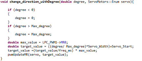
The ServoMotors.cpp file contains the change_direction_withDegree() function, which updates the PWM Match Register for the given PWM signal and the degree. This function takes the degree value, ensures that it is within range, then converts it into milliseconds so it can be written to the respective Match Register, using the PWMUpdateMR() function defined in the PWM driver file. We used the definitions Max_degree, Servo_Width, Servo_Start, and freq_ms, whose values may need to be changed if a different servo motor is used. Max_degree is the farthest degree available to the servo motor (180), freq_ms is the duty cycle (20 ms), and the Servo_Width and Servo_Start are derived from the duty cycle thresholds (in ms) mapped to the degree range (0 - 180) of the servo motor.
Light-sensing Task
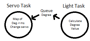
The Light-sensing task was very simple. To keep it this way, all of the 'heavy lifting' was completed in lower level code in the LightSensors.cpp file. Therefore, the only function that the Light-sensing task needs to use is the getDirection() function. However, there is a small amount of code to prevent the degree values from going out of range (0-180 degrees). The task reads the getDirection() values for both the top and base servo motors, which have valid values of negative five (-5), zero (0), or positive five (5). These values are added to the current positional value to obtain updated values to pass to the Servo Motor task through the Queue.
Servo Task
The Servo Task is even simpler. It takes the top and base positional values from the Queue, then passes the value to the servo motors using the change_direction_withDegree() function, which is defined in the ServoMotors.cpp file.
Testing & Technical Challenges
Describe the challenges of your project. What advise would you give yourself or someone else if your project can be started from scratch again? Make a smooth transition to testing section and described what it took to test your project.
Include sub-sections that list out a problem and solution, such as:
Wifi Connection Issues
Many wifi connection issues were encountered. To solve this problem, a dedicated task was created to re-connect to wifi if the connection was ever lost.
Conclusion
Conclude your project here. You can recap your testing and problems. You should address the "so what" part here to indicate what you ultimately learnt from this project. How has this project increased your knowledge?
Project Video
Upload a video of your project and post the link here.
Project Source Code
Send me your zipped source code and I will upload this to SourceForge and link it for you.
References
Acknowledgement
Any acknowledgement that you may wish to provide can be included here.
References Used
List any references used in project.
Appendix
You can list the references you used.
