Difference between revisions of "F16: AutoNav"
Proj user16 (talk | contribs) (→Testing & Technical Challenges) |
Proj user16 (talk | contribs) (→Hardware/Software Interface) |
||
| Line 583: | Line 583: | ||
=== Hardware/Software Interface === | === Hardware/Software Interface === | ||
| − | + | '''''I/O Interface - LCD''''' | |
The LCD is used to display some of the features to its application in our project.The sensor, GPS and current coordinates are displayed on LCD. The LCD we bought is from 4D systems and is very convenient and efficient to use. It has its own software which enables us to work in 4 different modes. We chose the mode which gave us different tools to build the compass, buttons and the angulometer. Bluetooth to serial converter is used to program the LCD with the software. We used the tools (that came with the LCD Module), to picturize our LCD screens. We loaded the program into LCD's memory card. The program that we burned on LCD will use the data bytes we send from our microcontroller and will print those bytes appropriately on different elements that we had created. For example, there are 360 degrees values to show on angulometer. The microcontroller will give a value from 0-360 based on the CAN frame which consists of car speed, heading and bearing values broadcasted by the Geo controller. In this way, almost every parameter being exchanged on the CAN bus of the car is displayed. | The LCD is used to display some of the features to its application in our project.The sensor, GPS and current coordinates are displayed on LCD. The LCD we bought is from 4D systems and is very convenient and efficient to use. It has its own software which enables us to work in 4 different modes. We chose the mode which gave us different tools to build the compass, buttons and the angulometer. Bluetooth to serial converter is used to program the LCD with the software. We used the tools (that came with the LCD Module), to picturize our LCD screens. We loaded the program into LCD's memory card. The program that we burned on LCD will use the data bytes we send from our microcontroller and will print those bytes appropriately on different elements that we had created. For example, there are 360 degrees values to show on angulometer. The microcontroller will give a value from 0-360 based on the CAN frame which consists of car speed, heading and bearing values broadcasted by the Geo controller. In this way, almost every parameter being exchanged on the CAN bus of the car is displayed. | ||
Revision as of 08:26, 21 December 2016
Contents
- 1 Project Title
- 2 Abstract
- 3 Objectives & Introduction
- 4 Team Members & Responsibilities
- 5 Schedule
- 6 Parts List & Cost
- 7 DBC File Implementation
- 8 Design & Implementation
- 9 Sensor Controller
- 10 Motor & I/O Controller
- 11 Bluetooth and Bridge(Android) Connections
- 12 Geographical Controller
- 13 Master Controller
- 14 Testing & Technical Challenges
- 15 Conclusion
- 16 References
Project Title
- Autonomous RC Car
Abstract
This project report describes an attempt to develop an autonomous RC car which navigates from a source point to destination avoiding any obstacles in between. The project was divided into five modules namely Motor & Input/output Controller, Sensor Controller, Geo Controller, Communication Bridge & Android Controller and Master Controller, each performing specific set of tasks. Each of the five modules were established using SJOne Boards. Communication between all the five modules was established using CAN Bus.
- Motor & I/O Controller - This controller was responsible for driving Brushless DC Motor interfaced through ESC, driving the stepper motor for steering and displaying the status of the RC car (speed, obstacle distance etc.) on the LCD.
- Sensor Controller - This controller was responsible for obstacle detection and avoidance, interfacing done with Ultrasonic Ping Sensors.
- Geo Controller - This controller focused on providing orientation (heading and bearing) and navigation route to the car.
- Communication Bridge & Android Controller - Co-ordinates for navigation were provided by this controller using an android application. Communication was established via Bluetooth.
- Master Controller - This controller was responsible for collecting the data from all the controllers, develop and implement obstacle avoidance algorithm to guide the car towards the final destination.
Objectives & Introduction
The main objectives of this project include:
- To develop an autonomous RC Car.
- To navigate from a set source to destination.
- To avoid any obstacles in between.
- To establish all communication between controllers via CAN bus.
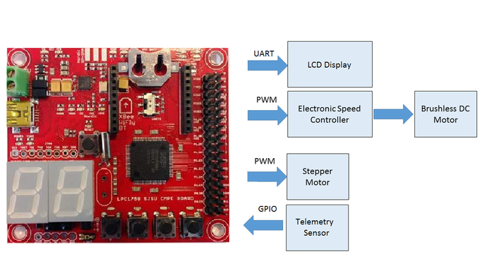
The following peripherals of LPC 1758 were used to establish communications:
- CAN Peripheral: Communicate between all the controllers on a common CAN bus.
- UART Peripheral: Communicate between GEO Controller and GPS module, Bluetooth controller and Bluetooth module.
- GPIO: Communicate between sensors and sensor controller.
- PWM: Vary the speed of Brushless DC motor and Stepper motor via ESC interfaced through Motor Controller.
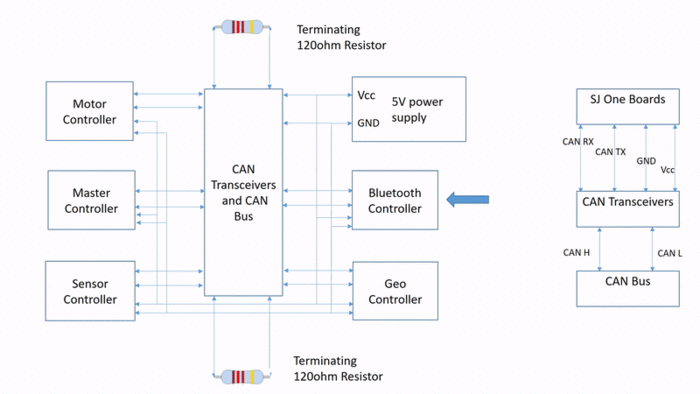
The block diagram below gives an overview of the various peripherals used:
Team Members & Responsibilities
Sensor Controller:
- Vishwanath Balakuntla Ramesh
Motor & I/O Controller:
- Sameer Saran
- Jaswanth Bhimanapalli
Bluetooth (Communication Bridge) & Android Controller:
- Sucharitha
- Karthikeya Rao G V
Geographical Controller:
- Arpita Ramanath
- Veena Manasa Kanakamalla
Master Controller:
- Ajai Krishna Velayutham
- Goutam Madhukeshwar Hegde
Schedule
Consolidated Team Schedule
| SI No. | Start Date | End Date | Task | Status | Actual Completion Date |
|---|---|---|---|---|---|
| 1 | 09/13/2016 | 09/27/2016 |
|
Completed | 09/26/2016 |
| 2 | 09/27/2016 | 10/11/2016 |
|
Completed | 10/11/2016 |
| 3 | 10/12/2016 | 10/18/2016 |
|
Completed | 10/20/2016 |
| 4 | 10/19/2016 | 10/30/2016 |
|
Completed | 11/01/2016 |
| 5 | 10/31/2016 | 11/08/2016 |
|
Completed | 11/12/2016 |
| 6 | 11/09/2016 | 11/27/2016 |
|
Completed | 11/29/2016 |
| 7 | 11/27/2016 | 12/15/2016 |
|
Completed | 12/18/2016 |
Parts List & Cost
| Item# | Part Description | Vendor | Qty | Cost |
|---|---|---|---|---|
| 1 | RC Car | RChobby Explosion | 1 | $190 |
| 2 | RC Car Battery | Amazon | 1 | $27.29 |
| 3 | CAN Transceiver | Texas Instruments | 15 | Free |
| 4 | M-F,F-F,M-M Jumper Wires | Amazon | 120 | 7.97 |
| 5 | Printed Circuit Boards | Amazon | 1 | $9.72 |
| 6 | Ultrasonic Parallax Ping Sensor | Fry's Electronics | 3 | $98.85 |
| 7 | 9 DOF Razor IMU module | SparkFun | 1 | $74.95 |
| 8 | Bluetooth Module | Amazon | 1 | $9.99 |
| 9 | GPS Sensor | Adafruit | 1 | $44.38 |
| 10 | Black/White line detection sensor - RPM sensor | Amazon | 1 | $10.10 |
| 11 | SJOne Boards | From Preet | 5 | $400 |
| 12 | LCD | 4D systems | 1 | $111 |
DBC File Implementation
DBC files are widely used to define the system of CAN messages and their constituent signals. This allows CAN data to be accessed in terms of human-usable signal values, with different data types and scaling, instead of just raw message bytes. Below is the DBC file that we implemented in our project.
VERSION ""

NS_ :
	BA_
	BA_DEF_
	BA_DEF_DEF_
	BA_DEF_DEF_REL_
	BA_DEF_REL_
	BA_DEF_SGTYPE_
	BA_REL_
	BA_SGTYPE_
	BO_TX_BU_
	BU_BO_REL_
	BU_EV_REL_
	BU_SG_REL_
	CAT_
	CAT_DEF_
	CM_
	ENVVAR_DATA_
	EV_DATA_
	FILTER
	NS_DESC_
	SGTYPE_
	SGTYPE_VAL_
	SG_MUL_VAL_
	SIGTYPE_VALTYPE_
	SIG_GROUP_
	SIG_TYPE_REF_
	SIG_VALTYPE_
	VAL_
	VAL_TABLE_

BS_:

BU_: DRIVER BLUETOOTH SENSOR MOTOR GEO

BO_ 100 KILL_SWITCH: 1 DRIVER
 SG_ killSwitch : 0|1@1+ (1,0) [0|0] "Stop=1" MOTOR

BO_ 110 STOP_CMD: 1 BLUETOOTH
 SG_ BLUETOOTH_STOP_CMD_signal : 0|1@1+ (1,0) [0|0] "Stop=1" DRIVER

BO_ 120 MOTOR_SYNC: 1 MOTOR
 SG_ Motor_Sync : 0|1@1+ (1,0) [0|0] "MotorSync=1" DRIVER

BO_ 130 GEO_SYNC: 1 GEO
 SG_ Geo_sync_cmd : 0|1@1+ (1,0) [0|0] "GeoSync=1" DRIVER

BO_ 140 BLUETOOTH_SYNC_CMD: 1 BLUETOOTH
 SG_ BLUETOOTH_SYNC_CMD_signal : 0|1@1+ (1,0) [0|0] "BluetoothSync=1" DRIVER

BO_ 150 SENSOR_SYNC: 1 SENSOR
 SG_ Sensor_Sync : 0|1@1+ (1,0) [0|0] "SensorSync=1" DRIVER,MOTOR,BLUETOOTH

BO_ 160 ERROR_COMM_DRIVER: 1 DRIVER
 SG_ Sync_Miss_Info : 0|8@1+ (1,0) [0|0] "ErrorMsgType" MOTOR

BO_ 170 DRIVER_SYNC_ACK: 1 DRIVER
 SG_ Sync_Miss_Info : 0|1@1+ (1,0) [0|0] "DriverSync=1" MOTOR,BLUETOOTH,SENSOR,GEO

BO_ 180 MOTOR_CONTROL: 2 DRIVER
 SG_ steer : 0|8@1+ (1,0) [0|0] "DirectionType" MOTOR
 SG_ speed : 8|8@1+ (1,0) [0|0] "SpeedType" MOTOR

BO_ 181 MOTOR_RPS: 2 MOTOR
 SG_ Rps_Sensor : 0|8@1+ (1,0) [0|0] "RotationsPerSecondENum" DRIVER,BLUETOOTH
 SG_ Rps_Value : 8|8@1+ (1,0) [0|0] "RotationsPerSecondValue" BLUETOOTH,DRIVER

BO_ 190 SENSOR_SONAR: 5 SENSOR
 SG_ Sensor_Sonar_Front : 0|8@1+ (1,0) [0|0] "FrontDistance" DRIVER,MOTOR,BLUETOOTH
 SG_ Sensor_Sonar_FrontRight : 8|8@1+ (1,0) [0|0] "FRightDistance" DRIVER,MOTOR,BLUETOOTH
 SG_ Sensor_Sonar_FrontLeft : 16|8@1+ (1,0) [0|0] "FLeftDistance" DRIVER,MOTOR,BLUETOOTH
 SG_ Sensor_Sonar_Back : 24|8@1+ (1,0) [0|0] "BackDistance" DRIVER,MOTOR,BLUETOOTH

BO_ 200 GEO_SEND_LOCATION: 8 GEO
 SG_ Geo_latitude : 0|32@1+ (0.000001,-90.000000) [-90|90] "latitude" DRIVER,BLUETOOTH,MOTOR
 SG_ Geo_longitude : 32|32@1+ (0.000001,-180.000000) [-180|180] "longitude" DRIVER,BLUETOOTH,MOTOR

BO_ 210 GEO_SEND_HD_BR: 8 GEO
 SG_ Geo_heading : 0|29@1+ (0.000001,0) [0|360] "" DRIVER,MOTOR
 SG_ Geo_bearing : 29|29@1+ (0.000001,0) [0|360] "" DRIVER,MOTOR

BO_ 220 NAVIGATION_WAYPOINT: 2 BLUETOOTH
 SG_ Bluetooth_CurrWaypoint : 0|5@1+ (1,0) [0|0] "CurrentWaypointNumber" DRIVER,GEO
 SG_ Bluetooth_NumWaypoint : 5|5@1+ (1,0) [0|0] "NumberOfWaypoints" DRIVER,GEO

BO_ 250 LATITUDE_LONGITUDE: 8 BLUETOOTH
 SG_ Bluetooth_latitude : 0|32@1+ (0.000001,-90.000000) [-90|90] "latitude" DRIVER,GEO
 SG_ Bluetooth_longitude : 32|32@1+ (0.000001,-180.000000) [-180|180] "longitude" DRIVER,GEO

BO_ 230 START_CMD: 1 BLUETOOTH
 SG_ BLUETOOTH_START_CMD_signal : 0|8@1+ (1,0) [0|0] "" DRIVER

BO_ 240 SENSOR_BATTERY: 8 SENSOR
 SG_ Sensor_Battery_Voltage : 0|8@1+ (0.1,0) [0|0] "Volts" DRIVER,MOTOR,BLUETOOTH
 SG_ Sensor_Battery_SOC : 8|10@1+ (0.1,0) [0|0] "Percent" DRIVER,MOTOR,BLUETOOTH
 SG_ Sensor_Light : 18|10@1+ (0.1,0) [0|0] "LightPercentValue" DRIVER,MOTOR,BLUETOOTH
 SG_ Sensor_Tilt_X : 28|12@1+ (0.1,0) [0|0] "TiltValueX" DRIVER,MOTOR,BLUETOOTH
 SG_ Sensor_Tilt_Y : 40|12@1+ (0.1,0) [0|0] "TiltValueY" DRIVER,MOTOR,BLUETOOTH

BO_ 500 DRIVER_TEST: 1 DRIVER
 SG_ Driver_Test_Msg : 0|8@1+ (1,0) [0|0] "" MOTOR,GEO,SENSOR,BLUETOOTH

BO_ 600 MOTOR_TEST: 1 MOTOR
 SG_ Motor_Test_Msg : 0|8@1+ (1,0) [0|0] "" DRIVER,GEO,SENSOR,BLUETOOTH

BO_ 700 SENSOR_TEST: 1 SENSOR
 SG_ Sensor_Test_Msg : 0|8@1+ (1,0) [0|0] "" DRIVER,MOTOR,GEO,BLUETOOTH

BO_ 800 GEO_TEST: 1 GEO
 SG_ Geo_Test_Msg : 0|8@1+ (1,0) [0|0] "" DRIVER,MOTOR,SENSOR,BLUETOOTH

BO_ 900 BLUETOOTH_TEST: 1 BLUETOOTH
 SG_ Bluetooth_Test_Msg : 0|8@1+ (1,0) [0|0] "" DRIVER,MOTOR,GEO,SENSOR

CM_ BU_ DRIVER "The DRIVER controller driving the car";
CM_ BU_ MOTOR "The motor controller of the car";
CM_ BU_ SENSOR "The sensor controller of the car";
CM_ BU_ GEO "The geo controller of the car";
CM_ BU_ BLUETOOTH "The bridge controller of the car";
CM_ BO_ 100 "Sync message used to synchronize the controllers";

BA_DEF_ "BusType" STRING ;
BA_DEF_ BO_ "GenMsgCycleTime" INT 0 0;
BA_DEF_ SG_ "FieldType" STRING ;

BA_DEF_DEF_ "BusType" "CAN";
BA_DEF_DEF_ "FieldType" "";
BA_DEF_DEF_ "GenMsgCycleTime" 0;

BA_ "GenMsgCycleTime" BO_ 500 10;
BA_ "FieldType" SG_ 180 steer "steer";
BA_ "FieldType" SG_ 180 speed "speed";
BA_ "FieldType" SG_ 181 Rps_Sensor "Rps_Sensor";
BA_ "FieldType" SG_ 190 Sensor_Sonar_Front "Sensor_Sonar_Front";
BA_ "FieldType" SG_ 190 Sensor_Sonar_FrontRight "Sensor_Sonar_FrontRight";
BA_ "FieldType" SG_ 190 Sensor_Sonar_FrontLeft "Sensor_Sonar_FrontLeft";
BA_ "FieldType" SG_ 190 Sensor_Sonar_Back "Sensor_Sonar_Back";

VAL_ 190 Sensor_Sonar_Front 3 "far_f" 2 "mid_f" 1 "near_f" 0 "danger_f" ;
VAL_ 190 Sensor_Sonar_FrontRight 2 "far_fr" 1 "mid_fr" 0 "near_fr" ;
VAL_ 190 Sensor_Sonar_FrontLeft 2 "far_fl" 1 "mid_fl" 0 "near_fl" ;
VAL_ 190 Sensor_Sonar_Back 2 "far_b" 1 "mid_b" 0 "near_b" ;
VAL_ 180 steer 4 "right" 3 "sright" 2 "sleft" 1 "left" 0 "straight" ;
VAL_ 180 speed 4 "brake" 3 "reverse" 2 "normal" 1 "slow" 0 "stop" ;
VAL_ 181 Rps_Sensor 2 "high" 1 "equal" 0 "low" ;
Design & Implementation
Please refer to the system block diagram below:
Description
Assuming the car would be given the necessary connections and be powered up to navigate, we would give the first signal to start the car from the Bluetooth device by sending a start signal of "1". Once the Start signal is received by the Master controller, it would receive the signals from the sensors and the GPS as well. Based on the data from all these systems, Master controller decides the command to be given to the Motor controller. Motor on receiving the instructions from the Master would move in a particular direction suggested by Master. Motor would also revert the path in which it is going, RPM values to Master, Bluetooth and LCD display over the CAN. Meanwhile the Bluetooth would be fetching the messages from the CAN and would filter out on the messages by their ID's and later send the required signals such as GPS and RPM values to the Android device, which is displayed to the user in their respective text boxes.
CAN BUS
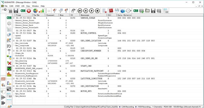
Below is the screenshot of the CAN Bus while Testing the CAR after integration.
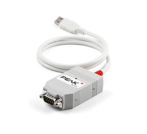
P-CAN would be connected to RX-480 Port on the CAR and other end to the system via USB on the system, shown in the image above.This would enable the user to view the CAN messages on the CAN Bus on his screen and would largely help to debug the error on all the controllers.
Sensor Controller
Team Members:
Vishwanath Balakuntla Ramesh
Hardware Design
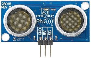
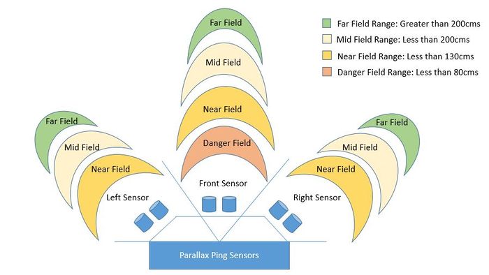
We used 3 Parallax Ping ultrasonic distance sensors for obstacle detection and avoidance. Non-contact distance can be measured from about 2 cm (0.8 inches) to 3 meters (3.3 yards).
The PING))) sensor works by transmitting an ultrasonic burst and providing an output pulse that corresponds to the time required for the burst echo to return to the sensor. By measuring the echo pulse width, the distance to target can easily be calculated.
Three sensors were placed in front (front_left, front_center, front_right).
Hardware Interface
Three parallax ping sensors are used (front, left and right). As shown above, in the hardware design of parallax ping sensor, VCC pin of all the three sensors is connected to 5V, GND is connected to ground and SIG of all the three sensors is connected to P2.0, P2.1, and P2.2 of SJ One board.
Parralax Ping Sensor Operation
Software Design
| Task Name | Purpose |
|---|---|
| Period Init | Enable and initialize LPC timer, Initialize CAN, rising and falling edge of GPIO Interrupt |
| Periodic 1Hz Callback | Check can bus off |
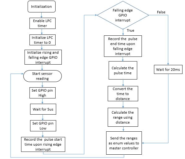
| Periodic 10Hz Callback | Get and Send Sensor Data |
Sensor_Sonar_Front_E calculate_range_front(double distance)
{
	if(distance>5&&distance<120)
		return danger_f;

	else if(distance<180)
		return near_f;

	else if(distance<250)
		return mid_f;

	else
		return far_f;
}


Sensor_Sonar_FrontRight_E calculate_range_frontRight(double distance)
{
	if(distance<100)
		return near_fr;

	else if(distance<200)
		return mid_fr;

	else
		return far_fr;
}


Sensor_Sonar_FrontLeft_E calculate_range_frontLeft(double distance)
{
	if(distance<100)
		return near_fl;

	else if(distance<200)
		return mid_fl;

	else
		return far_fl;
}


void start_trigger(GPIO trigger)
{
	trigger.setAsOutput();
	trigger.setHigh();
	delay_us(5);
	trigger.setLow();
}
Implementation
Motor & I/O Controller
Team Members:
Sameer Saran
Jaswanth Bhimanapalli
Hardware Design
Hardware/Software Interface
I/O Interface - LCD The LCD is used to display some of the features to its application in our project.The sensor, GPS and current coordinates are displayed on LCD. The LCD we bought is from 4D systems and is very convenient and efficient to use. It has its own software which enables us to work in 4 different modes. We chose the mode which gave us different tools to build the compass, buttons and the angulometer. Bluetooth to serial converter is used to program the LCD with the software. We used the tools (that came with the LCD Module), to picturize our LCD screens. We loaded the program into LCD's memory card. The program that we burned on LCD will use the data bytes we send from our microcontroller and will print those bytes appropriately on different elements that we had created. For example, there are 360 degrees values to show on angulometer. The microcontroller will give a value from 0-360 based on the CAN frame which consists of car speed, heading and bearing values broadcasted by the Geo controller. In this way, almost every parameter being exchanged on the CAN bus of the car is displayed.
The following is the link to the main page of the LCD. It contains everything you need to know to run this LCD and run it to the highest feature. It has the datasheet as well as the info regarding the software too. Go through the software datasheets as well as we will need that software to run the LCD initially. The LCD accepts any data from our microcontroller only if it is programmed that way by the software. http://www.4dsystems.com.au/product/uLCD_32PTU/ Next link is to the to the collection of go through materials for each every object the LCD uses. http://old.4dsystems.com.au/appnotes.php
Now, if you have gone through the software datasheets, you will be already have accustomed with the software and its fun too. Select your tool accordingly your requirement. Be creative. We needed to show magnetometer values, from 0 to 360 in order to debug whether the compass is pointing towards north exactly or not. So we used an angularometer under the Gauges tab. It will have all the properties associated with the object. You can test each of them. Now, the data sent from the microcontroller will be directly printed on the LCD to its position on the angulometer. In this way, we can easily know the direction of True North with the help of LCD. Alon with this there are some strings used on LCD which shows longitude, lattitude, etc. This string is also sent from the microcontroller. When you are done with the tools, put a memory card with a maximum of 2 GB of memory into your LCD and connect it serially to your PC. USB to serial converter is to be used here. Burn the software image onto your LCD. At this point, your LCD is programmed to show all the images and the tools and is ready to accept all the data from the controller and print them on itself. So now we have got to do, is only connect the controller with LCD and send data bytes with help of UART.
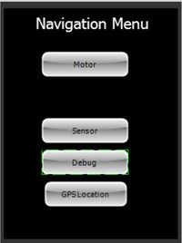
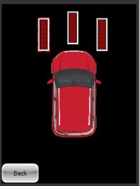
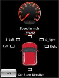
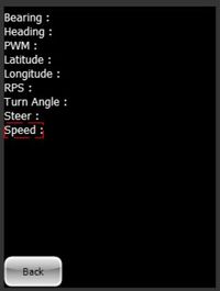
Below are the snaps of the LCD Screens:
| Screen No. | Description |
|---|---|
| 1 | Welcome Screen |
| 2 | Displaying the menu |
| 3 | Displaying Sensor data |
| 4 | Displaying motor data |
| 5 | Displaying data to debug along with GPS data |
Tasks
| Task Name | Purpose |
|---|---|
| Period Init | Initializing CAN bus, Motor, Interrupt for Motor Feedback and UART for LCD |
| Periodic 1Hz Callback | Displaying data on LCD and checking for CAN bus off |
| Periodic 10Hz Callback | Interpreting data from Master controller, driving car, calculating RPM |
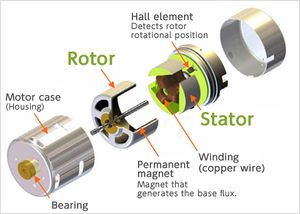
Brushless DC Motor
|
Our car came with 3650 Brushless inrunner motor, 2080KV with 60A ESC(with Reverse). This motor has the power to run the car at a maximum speed of the 35mph.
Table3: DC Motor Duty Cycle v/s Speed Control |
|
DC motor is controlled with the help of three wires coming out of the ESC. These wires are VCC, GND and Speed control. The VCC line is not used as required voltage is directly given to the motor through a battery, via ESC. The GND line and Speed control lines are connected to the ground and PWM pin of SJOne board.
DC Motor Pin Connections To drive the DC motor, we are using pwm2 i.e. pin P2.1 of the SJOne board. We are using the in-build PWM generation function which requires two parameters, one is pin being used and the other being the frequency. To set the required duty cycle, the in-build set function is used. Motor FeedbackInitially we used to calculate feedback at 1Hz using one magnet and a telemetry sensor and if the current RPM was less than required RPM then we used to switch to the higher hard coded PWM value, But since the DC motor was dependent on the battery's state of charge. We had to redesign the Motor Feedback, we added more magnets so that we get enough data so that we can react at a faster rate of 10Hz. To make the DC motor's speed independent of state of charge and dependent only on RPM we changed the Motors's Algorithm. Below is the Code snippet of DC Controller
void drive_DC(speed_E speed,int rpm)
{
	if(speed==reverse)
	{
        //Set DC to Reverse PWM Value
	}
	else if (speed==brake)
	{
	//Set DC to Brake PWM Value
	}
	else if (speed == stop)
	{
	//Set DC to Stop/Idle PWM Value
	}
	else
	{
	        ReqRPM=get_rpm(speed);

		if(DC Value id with in safe range)
		{
			if(rpm>ReqRPM)
			{
			//If current RPM is greater then Required RPM then Reduce Speed
			}
			else if(rpm<ReqRPM)
			{
			//If current RPM is lesser then Required RPM then Increase  Speed
			}

			else if(rpm==ReqRPM)
			{
		        //If current RPM is equal to required RPM the maintain same Speed
			}
		}
	}

}
|
Servo Motor
|
Our car came with a waterproof digital servo motor. This motor works without ESC. We can directly control this motor by giving PWM signal from our SJOne board. The below table contains information about PWM (duty cycle) given to the motor and the corresponding turns taken by the car.
Servo Motor Duty Cycle v/s Turn |
|
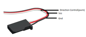
Servo motor is controlled with the help of three wires coming out of the servo motor. The wires are VCC, GND and Direction control. The VCC is connected to the 3.3v. GND and direction control are connected to the ground and pwm pins of SJOne board.
Servo Motor Pin Connections We control the Servo motor using pwm1 i.e. pin P2.0 of the SJOne board. We configure the PWM pin using an in-build function which requires two parameters, one is the pin that we are using and the other is the frequency of the pwm. To set the duty cycle, in-build set function is used in which we are passing the duty cycle at which we want servo motor to work. |
class MotorCtrl : public SingletonTemplate<MotorCtrl>
{
	public:
		MotorCtrl() : steerServo(PWM::pwm1),driveDc(PWM::pwm2)
		{
			//Constructor
		}
		void set_servo(float value) {steerServo.set(value);}
		void set_dc(float value){driveDc.set(value);}
		friend class SingletonTemplate<MotorCtrl>;

	private:
		PWM steerServo;
		PWM driveDc;

};

#define MotorCtrl MotorCtrl::getInstance()
Bluetooth and Bridge(Android) Connections
Team Members:
Sucharitha Sirigreddy
Karthikeya Rao G V
This section includes high level implementation details regarding the Android app connectivity with the Bluetooth module of the RC car. It gives a overview of building the android app, communication between the Bluetooth and Android app on a mobile device, and routing mechanisms during the navigation.
Bluetooth Controller Pin Connections
| Node A Source | Node A Pin | Node B Source | Node B Pin | Description |
|---|---|---|---|---|
| Power Supply | 3.3V | SJOne Board | 3V3 | SJOne Power |
| Power Supply | GND | SJOne Board | GND | SJOne Ground |
| CAN Transceiver | CAN Tx | SJOne Board | P0.1 (Tx) | SJOne - CAN Tx |
| CAN Transceiver | CAN Rx | SJOne Board | P0.0 (Rx) | SJOne - CAN Rx |
| Bluetooth Module | TXD | SJOne Board | RXD3 | SJOne RX3- Bluetooth module TXD |
| Bluetooth Module | RXD | SJOne Board | TXD3 | SJOne TX3- Bluetooth module RXD |
| Bluetooth Module | Bluetooth module VCC(3.3V) | Power Supply | 3.3V | Bluetooth module - Power supply 3.3V |
| Bluetooth Module | Bluetooth module GND | Power Supply | GND | Bluetooth module - Power supply GND |
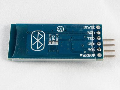
Below attached is the image of the Bluetooth Module HC-06.
Hardware Interface
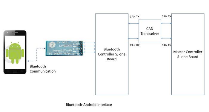
Below is the representation of the bridge communication.
Hardware Interface between the Bluetooth controller and the car system has been wired through the CAN bus. P0.1 is connected to CAN Tx and P0.0 is connected to CAN Rx, where communication between the Bluetooth module and other modules happen. RXD and TXD pins are connected to Bluetooth HC-06 to enable communication between the Android mobile device and the Bluetooth module. Power supply and Ground pins to SJone board i.e Bluetooth module is provided by battery, which would power up all the SJone boards. Power to the HC-06 module is given by the SJone Bluetooth board 3.3V and GND pins. Thus enabling the Interface between Bluetooth module and the other controllers.
Software Design
Software interface between HC-06 and Android device is enabled via Bluetooth transmission and reception.
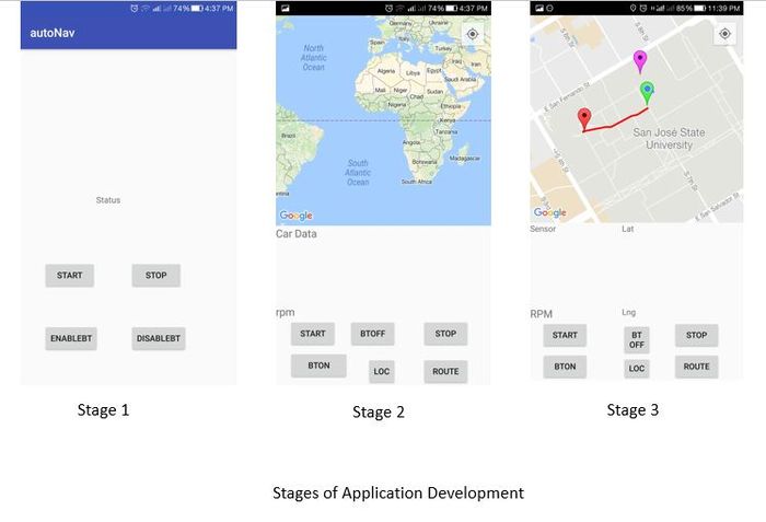
Below attached is the image showing the Android Application Development.
Initially we developed the Application with just Enable and Disable Bluetooth Buttons, after which we added the Start and Stop Signals Button. Start and Stop buttons were given the functionality to send "1" and "0" respectively. In the next phase, we integrated the application with Google maps with few more buttons and obtained our location from the Google maps and cell phone GPS and marked our location on the App screen. In the Final phase we were able to display the application with all the values which we received from the Bluetooth controller, which includes RPS and Locations.
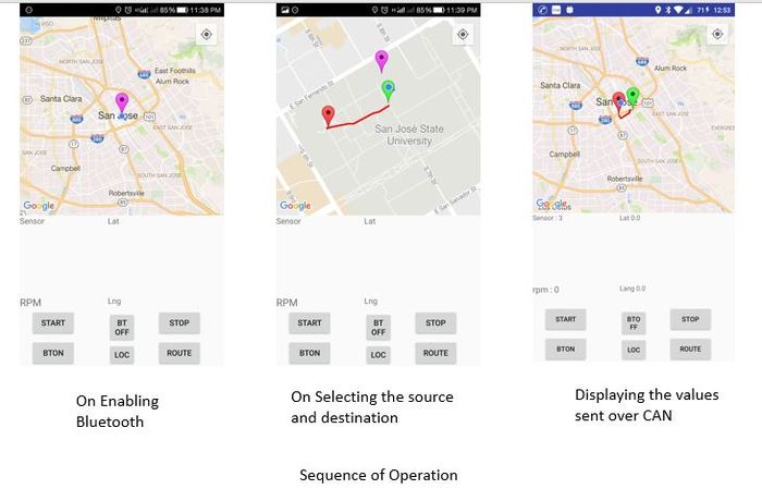
Below diagram represents the different app screens in the selection sequence.
In the above image, we initially turn on the Bluetooth device. Once done, we set up the start and destination on the map, marked as red and green flags respectively. Clicking on the Start signal would enable the Car to receive the Signals Route button would send out the way points to the Bluetooth controller and the Master sending the signal to move the car in the way points direction.
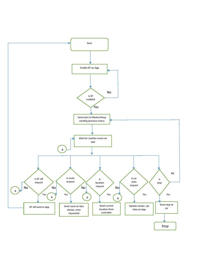
Flow Chart:
Flow Chart of the Bluetooth and Android design is as follows.
Android-Bluetooth Controller Button's Functionality Table
| SI No. | Button | Functionality |
|---|---|---|
| 1 | BTON | User is prompted to Turn on Bluetooth device on the phone. User can either "allow" or "deny" the request. Application won't work till the request is allowed. |
| 2 | START | Sends string 1 over Bluetooth channel to indicate to to Master Controller to start of car. |
| 3 | STOP CAR | Sends string 0 over Bluetooth channel to indicate to Master Controller to stop the car(Wireless Kill switch). |
| 4 | BTOFF | Turns off the Bluetooth of the Android device. |
| 5 | LOC | Places a marker on Google Map based on cars Latitude and Longitude received from the GEO module on the car. |
| 6 | ROUTE | Send route from source to destination selected on map after filtering way-points to the Bluetooth Controller and to GEO controller there on. |
Implementation
Through the Android application the Bluetooth would be paired with HC-06 module on click of BTon button, which turns on the Bluetooth on the android phone and connects to Car’s HC-06 Bluetooth device. Post which, we would send a start signal from the app, which would sync and start the car. This signal is hardcoded as ‘1’, and is encoded before sending from the android. This signal when received from the Bluetooth module, would decode and read the message and later encode and pass it on over the CAN to the Master.
After this syncing, the Master would initiate other modules; post which GPS module would send the location signal over the CAN. This signal is again decoded and sent over to the Android as a line having latitude and longitude and prefixed with respective signals, ex: RPM for RPM values and post-fixed with “!” , for easier identification in the Android. Location button would enable the current location of the device, which would be marked on the map, this would be enabled on click of start itself. This would also enable Bluetooth module to detect the messages over the CAN to be displayed on the app, like RPM values and GPS data. These are again encoded and sent over to Android, which would display them in respective text boxes.
Route Button on the app would be initiated once we set these and the source and destination by 2 clicks on the maps in the app and start getting the GPS location from HC-06. Route Button on click would detect the GPS location from the car and send out next way points till the destination. The Kill switch is implemented as Stop Button, which sends of “0” signal, which is received by the Bluetooth and sent over the CAN Bus to master, to stop the Motor.
Geographical Controller
Team Members:
Veena Manasa Kanakamalla
Arpita Ramanath
Hardware Design
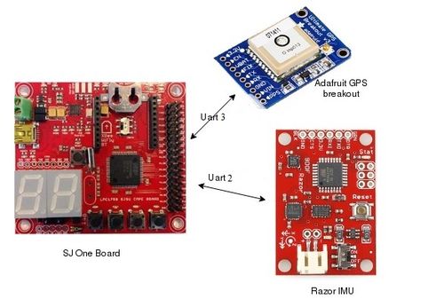
System Block Diagram
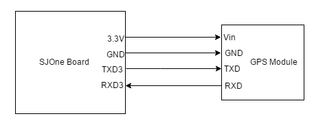
SJ One board is interfaced to GPS module and IMU through UART.
Geographical Controller Hardware Design Components
|
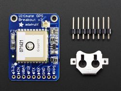
Adafruit MTK3339 GPS: This GPS unit is interfaced via UART with build in antenna. The GPS provides latitude and longitude accurately up to 5-10 meters with a strong satellite fix with update rate of 10Hz. By default, the baud rate is 9600bps. Power usage for this module is 20mA during navigation. The GPS module comes with following capabilities:
We chose this part because it provided the base functionality we needed along with many other functions that would be fun to play with and try to include in the project. The antennae options and voltage regulator were also very enticing. We get raw GPS "NMEA sentence" output from module. The most important NMEA sentences include the GGA which provides the current Fix data, the RMC which provides the minimum gps sentences information, and the GSA which provides the Satellite status data. We are filtering the data for GGA (Time, Position and Fix type data), which will look similar to: GGA- essential fix data which provide 3D location and accuracy data. $GPGGA,123519,4807.038,N,01131.000,E,1,08,0.9,545.4,M,46.9,M,,*47
GGA Global Positioning System Fix Data
123519 Fix taken at 12:35:19 UTC
4807.038,N Latitude 48 deg 07.038' N
01131.000,E Longitude 11 deg 31.000' E
1 Fix quality:
0 = invalid
1 = GPS fix (SPS)
2 = DGPS fix
3 = PPS fix
4 = Real Time Kinematic
5 = Float RTK
6 = estimated (dead reckoning) (2.3 feature)
7 = Manual input mode
8 = Simulation mode
08 Number of satellites being tracked
0.9 Horizontal dilution of position
545.4,M Altitude, Meters, above mean sea level
46.9,M Height of geoid (mean sea level) above WGS84
ellipsoid
(empty field) time in seconds since last DGPS update
(empty field) DGPS station ID number
*47 the checksum data, always begins with *
|
||
|
GPS Pin Connections 9 Degrees of Freedom- Razor IMU: In our project, we used IMU module to get the heading of the device. The 9DOF Razor IMU provides nine degree of inertial measurement incorporates three sensors - an ITG-3200 (MEMS triple-axis gyro), ADXL345 (triple-axis accelerometer), and HMC5883L (triple-axis magnetometer). The outputs of all sensors are processed by an on-board ATmega328 and output over a serial interface. UART interface is used for interfacing with SJ One board and it is connected via UART3 with LPC board and is operated at 3.3V. Features:
|
IMU Pin Connections
Hardware Interface
Geographical Controller H/W Interface
- Below table shows the pin connections of GPS and IMU module with SJ One Board. Both the modules are interfaced with Controller using UART interface. The operating voltage of GPS and IMU is 5V.
| Description | Interface | Port Used | Controller Port |
|---|---|---|---|
| Supply Voltage | N/A | 5V power supply | N/A |
| Ground | N/A | GND | GND |
| GPS Module | UART3 |
1 -> Rx 2 -> Tx |
1 -> Tx P4.28 2 -> Rx P4.29 |
| IMU Module | UART2 |
1 -> Rx 2 -> Tx |
1 -> Tx P2.8 2 -> Rx P2.9 |
Software Design
Geographical controller uses two modules to get GPS data and heading. These are:
- GPS module
- IMU module
Tasks
| Task Name | Purpose |
|---|---|
| Period Init | Initializing CAN bus, UART2 for IMU, UART3 for GPS |
| Periodic 1Hz Callback | Checking for CAN bus off |
| Periodic 10Hz Callback | Receiving and parsing GPS data and IMU data, receiving checkpoints, calculating heading, bearing and distance. |
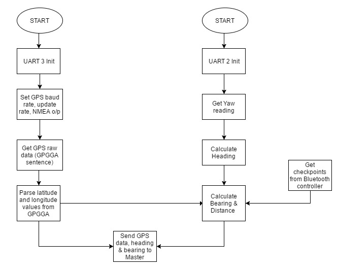
Flowchart
Implementation
Receiving and parsing GPS data
The first task was to interface the GPS module to the SJOne board (using UART3), and receive raw data over it. The module was configured to receive only GPGGA NMEA sentence at 9600 bps baud rate. The received NMEA data is a string, that has to be parsed to obtain current latitude and longitude values. This location data is continuously sent to the Master controller on the CAN bus at 10 Hz.
Heading Calculation
Heading of the car is the direction that the car is moving, with respect to true north. A compass gives heading with respect to magnetic north. True heading is calculated by adding magnetic declination at that particular location, to the magnetic heading.
The IMU module has to be calibrated initially. The board comes programmed with the 8MHz Arduino bootloader (stk500v1) and some example firmware that demos the output of all the sensors (accelerometer, magnetometer, gyroscope). The calibration was done by following this tutorial at https://github.com/Razor-AHRS/razor-9dof-ahrs/wiki/Tutorial. Calibration compensates for the magnetic field around the IMU. So this process has to be done once after mounting the IMU on the car.
The IMU module is interfaced to the SJOne board using UART2. The IMU firmware is updated such that it gives only Yaw readings. Yaw (or magnetic heading) is used to calculate the true heading using the below formula.
Heading = Yaw data from IMU + Magnetic Declination
Magnetic declination in San Jose is +13° 29'.
Bearing calculation
Bearing is the direction that the car desires to travel along, i.e., the direction of the destination. It is calculated using the current location coordinates and the destination coordinates (or next checkpoint coordinates). The formula to calculate bearing is
   X = cos(lat2) * sin(dLong)
   Y = cos(lat1) * sin(lat2) - sin(lat1) * cos(lat2) * cos(dLong)
   Bearing = atan2(X,Y)

   where,
   (lat1, long1) are the current location coordinates
   (lat2, long2) are the checkpoint coordinates
   dLong is (long2 - long1)
Distance calculation
The distance between the current location and the next checkpoint is calculated using the below formula.
Haversine formula to calculate distance
  a = sin²(Δφ /2) + (cos φ1 ⋅ cos φ2 ⋅ sin²(Δλ/2))
  c = 2 x atan2( √a, √(1−a) )
  Distance d = R x c
       Where,
            Φ is latitude
            λ is longitude
            R is Earth’s radius = 6371 Km
            Δφ = latitude2 – latitude1
            Δλ = longitude2 – longitude1
A flag is set when the distance to the final checkpoint becomes zero, and sent to the Master controller, to indicate that the destination has been reached.
Master Controller
Team Members:
Ajai Krishna Velayutham
Goutam Madhukeshwar Hegde
The Master Controller receives obstacle information from the Sensor Controller, navigation data from the Geo Controller and routing information from the Bluetooth Controller, collates all this information and provides driving directions to the Motor Controller.
Hardware Design
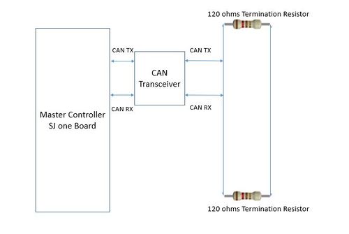
The diagram shows the connections for the Master Controller
Hardware Interface
In this section, you can describe how your hardware communicates, such as which BUSes used. You can discuss your driver implementation here, such that the Software Design section is isolated to talk about high level workings rather than inner working of your project.
Software Design
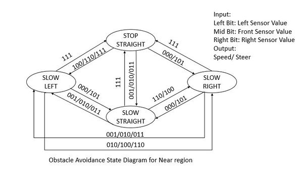
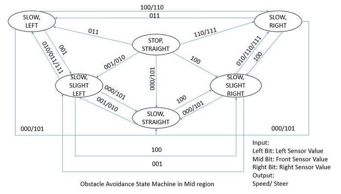
Obstacle avoidance algorithm: Obstacle avoidance is done according to the enum values sent from the sensor controller. In the master controller, obstacle avoidance is handled separately in danger,near and medium regions. If sensor indicates danger region,it means that there is an obstacle very near to front sensor. So in this case car takes a reverse turn until the front sensor enters near region.So in this way car avoids obstacle very near to it. If sensor indicates near region,master enters a states machine to intelligently avoid the obstacle as shown the above figure. If sensor indicates medium region,master enters another state machine to handle the obstacles in medium region.
Navigation Algorithm:
GPS Navigation is done based on the heading and bearing values from GEO controller.Master controller calculates the desired turn angle to reach the destination path.
Turn angle= GPS bearing-GPS heading;
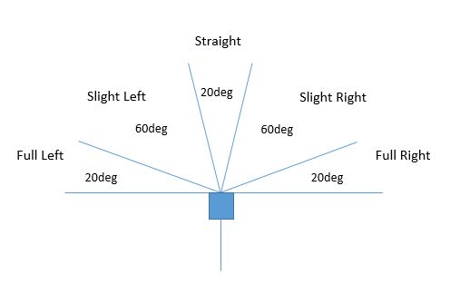
Turn angle is a value between 0 to 360 degree.Entire 360 degrees is divided into various sub-regions based on the desired turn angles as shown in the above figure. GPS navigation is done with the help of a state machine.Turn angle is the input for the state machine based on which state machine determines the command to issue to the motor.
Implementation
This section includes implementation, but again, not the details, just the high level. For example, you can list the steps it takes to communicate over a sensor, or the steps needed to write a page of memory onto SPI Flash. You can include sub-sections for each of your component implementation.
Testing & Technical Challenges
Motor & I/O Issues
- Reverse Current from Motor: One of our boards got burnt while testing Brushless DC Motor. We would highly recommend using an Optoisolator such as ILQ74 for additional protection from reverse current etc. if you are synchronizing with the ESC for the first time.
- ESC Synchronization: The slowest speed of Brushless DC motor was too fast for us. We tried to change ESC synchronization and reprogram it to change PWM frequency but it didn't work out for us. We recommend having Brushed DC Motor that is reprogrammable to any PWM frequency.
- ESC Modes: ESC Board was only set to forward and reverse mode. So we were not able to control the speed to stop the motor, even after sending stop signal it would hit the obstacle. So we reprogrammed the ESC to forward, reverse and brake. Synchronizing took time and effort. ESC has various modes we can program it into.
- Going Reverse issues: If we wanted to go reverse first without going forward, car would go full speed in reverse. So every time we got reverse command from master, we initialized the DC motor to idle and then go to reverse.
- LCD Refresh Rate Issue: For debugging, we wanted to run LCD at 10hz but it took long time to refresh, so data didn't get printed. Hence we were forced to debug especially at 1 Hz.
Bluetooth Bridge Controller and Android application Issues
Issues
- During the initial phase we were finding difficult to connect to the Bluetooth Module HC-06, later on proper UUID was given which solved the connection issue.
- Sending out Start and Stop messages of "1" and "0" respectively continuously was a challenge. This was required to detect when Bluetooth goes out of range. We solved this issue using threads.
- We had tested the application by hard coding the values from the Bluetooth controller end, which was displayed as messages on the application. The requirement was to display the CAN messages, therefore once we integrated on board, we faced issues like receiving junk and ? character on the application. We solved this by introducing circular buffers.
- On integrating with on board GPS, we were unable to send out all the Navigation way points, say if we got 8 way points, we were able to send only first 4 of them. This was due to buffer size which we had set to 100. Once we updated it to 500, we were able to receive all the CAN messages flawlessly.
Testing
- At Module level, we tested the communication between the Bluetooth Controller and the Android by sending out characters through UART and displaying the received messages on the app screen.
- We increased the number of characters to 960 characters that was being sent on UART to check whether we were able to receive on the app.
- Verified the Location of the maps on the app with the Google maps application.
- Verified the messages displayed on the Bus Master and LCD with the app screen post integration.
Project Hardware Issues
Geo controller Issues
- While initially testing IMU in raw data mode, the module was providing improper data values. We had to calibrate the Gyrometer and Magnetometer to get exact angles with precision of +/- 2 degrees. Even after this, the magnetometer's readings were changing when any soft/hard iron object was taken near the sensor. In order to remove electromagnetic interference generated from DC motor, we had to place our IMU far from DC Motor. The IMU has to be calibrated once again after mounting it on the car to avoid drift in the Yaw values.
- The GPGGA sentence received via UART was incomplete sometimes, resulting in incorrect parsing. This turned out to be an issue with the UART receive queue size. When this queue size was increased, complete NMEA sentences were received.
- Initially, the coordinates received from the GPS module were pointing to Santa Clara, around 30 km away from our present location. This was due to incorrect parsing of the NMEA sentence from the GPS module. The latitude and longitude values from the GPS module are given in the form of ddmm.mmmm and dddmm.mmmm and not decimal degrees. The minutes have to be converted to degrees and added to the degrees value.
Master Controller Issues
Miscellaneous Issues
Conclusion
In a span of 3 months, we had an awesome experience in working together for the AutoNav project. We learnt a lot about GIT and CAN bus along with implementing DBC and working on real hardware. We were able to implement all these embedded concepts effectively from our course work. All essential phases of software development cycle such as design, implementation and testing were executed in stages effectively and debugging with CAN bus was really helpful in working. Finally it was an enchanting experience and we hope that we were able to share some of our learnings and difficulties we faced in this report, which would help the future students joining the course.
Project Video
Upload a video of your project and post the link here.
GitLab Source Code
References
Acknowledgement
Any acknowledgement that you may wish to provide can be included here.
References Used
List of references used in the project.
[1] Preetpal Kang's lecture notes of CMPE 243, Computer Engineering, San Jose State University, Aug-Dec 2016.
[2] LPC1758 User Manual
[3] Parallax Ultrasonic Sensor
[4] Razor IMU
[5] Razor IMU Tutorial
[6] Adafruit Ultimate GPS Breakout - 66 channel w/10 Hz updates - Version 3
[7] Calculate distance between two points
[8] Programming Guide
[9] Google Maps Guide
[10] Video guide for Google maps implementation
Appendix
You can list the references you used.

