Difference between revisions of "S16: Autonomous Lane Changer"
Proj 146u1 (talk | contribs) (→Hardware Interface) |
Proj 146u1 (talk | contribs) (→Hardware Interface) |
||
| Line 170: | Line 170: | ||
* '''Analog Digital Converter (ADC)''' | * '''Analog Digital Converter (ADC)''' | ||
For this project, we utilized 6 analog IR emitter/receiver pair sensors. Because they were analog sensors, couldn't have connected these sensors directly to any GPIO pins, but needed to connect them to the ADC pins. Because we had more sensors than available ADC pins, we used an analog multiplexer to hold multiple analog inputs, and connected the common output a single ADC pin. | For this project, we utilized 6 analog IR emitter/receiver pair sensors. Because they were analog sensors, couldn't have connected these sensors directly to any GPIO pins, but needed to connect them to the ADC pins. Because we had more sensors than available ADC pins, we used an analog multiplexer to hold multiple analog inputs, and connected the common output a single ADC pin. | ||
| + | |||
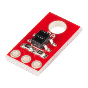
| + | [[File:CmpE146_S16_Sensor.jpg|300px|thumb|center|Analog IR Line Following Sensor]] | ||
Revision as of 02:48, 23 May 2016
Contents
Grading Criteria
- How well is Software & Hardware Design described?
- How well can this report be used to reproduce this project?
- Code Quality
- Overall Report Quality:
- Software Block Diagrams
- Hardware Block Diagrams
- Schematic Quality
- Quality of technical challenges and solutions adopted.
Autonomous Lane Changer
Abstract
This project proposes an autonomous RC car that follows lines along the sides that can also change lanes when possible. In the real world, cars driven on the street follow lane markers, unless the car is trying to change lanes. Cars can only change lanes when the lane lines are broken. While autonomous cars are becoming increasingly popular, one of the things to consider besides the car driving itself is the way the car operates on the street, two of those things being to stay within lane markers and changing lanes. Other line following cars follow lines directly in front of them; however, our vehicle will follow lines on its side. When the lines along the side of the car are broken, our car will be able to change lanes. Doing so allows these cars to be integrated onto real city streets without having to change current road infrastructure that are already in place. The aim of this project is to mimic this idea at a smaller scale in hopes of not only finding a way for autonomous vehicles to be integrated onto existing city streets, but also for us, as inexperienced students, to learn an important skills that will be applied in our future careers.
Objectives & Introduction
Typical line following RC cars follow lines directly below and in the middle of the car. While this is a great design for the concept, we wanted to change it so that a line following RC car mimics real world self-driving cars by following real lanes on streets. The objective of this project is to create a lane following robot capable of changing lanes when necessary.
In order to achieve this, our group utilized IR receiver pair sensors to sense the road below and the lane lines along the side. In order to implement a lane changing feature, we decided to utilize the board's wireless functionality to communicate to the car when to change lanes.
Team Members & Responsibilities
- Patrick-Daniel Llanes
- Programming Sensors
- Programming Line Following Algorithm
- Programming Lane Changing Capability
- Report Writing
- Jonathan Lo
- Car assembly
- Sensor Mounting
- Programming Line Following Algorithm
- Programming Lane Changing Capability
- Report Writing
Schedule
| Week# | Date | Task | Status | Completion Date |
|---|---|---|---|---|
| 1 | 4/6 | Gathered and ordered parts for Autonomous Lane Changer. | Completed. | 4/11 |
| 2 | 4/11 | Begin building autonomous car. | Completed. | 4/18 |
| 2a | 4/13 | Complete build and begin testing IR sensors and motors. | Completed. | 4/18 |
| 3 | 4/17 | Compute PWM duty cycles for motors. | Completed. | 4/19 |
| 3a | 4/20 | Integrate IR sensors and begin testing sensors. | Completed. | 4/22 |
| 4 | 4/24 | Finalize project and begin testing and debugging. | Completed. | 5/19 |
| 5 | 5/2 | Finish testing. | Need to fine tune turning and lane changing. | |
| 5a | 5/6 | Finalize project and prepare car for demo purposes. | Fine tuning turning and lane changing. |
Parts List & Cost
| Quantity | Description | Price |
|---|---|---|
| 2 | SJone Boards | $80 each = $160 |
| 1 | Shadow Chassis | $12.95 |
| 1 | Wheel-65mm (Rubber Tire, Pair) | $2.95 |
| 6 | SparkFun Line Sensor Breakout QRE1113 (Analog) | $2.95 each = $17.70 |
| 2 | Motors | $3.95 per pair |
| 1 | MC14051 Analog Multiplexer | $0.49 |
| 1 | Light colored masking tape | $5.00 |
| 30 | Jumper Cables | Free |
| 1 | Black Duct Tape | $8.99 |
| 2 | 220 Ohm Resistor | Free |
| 2 | PN2222 Transistor | Free |
| Total Cost | $212.03 |
Design & Implementation
Hardware Design
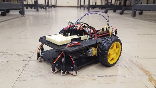
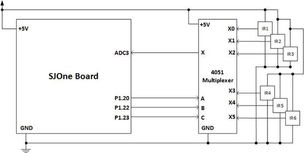
To create an autonomous lane changer RC, IR emitters and receivers were used to detect lines under the RC car. The IR emitter is a source of light energy and the levels of reflectivity are received by the IR receivers. Due to the limited amount of ADC pins available on the SJOne board compared to the amount of analog sensors we implemented, we used the MC14051 Analog Multiplexer with digital controls, allowing us to implement more analog peripherals to our board, and controlling them digitally using 3 GPIO pins.
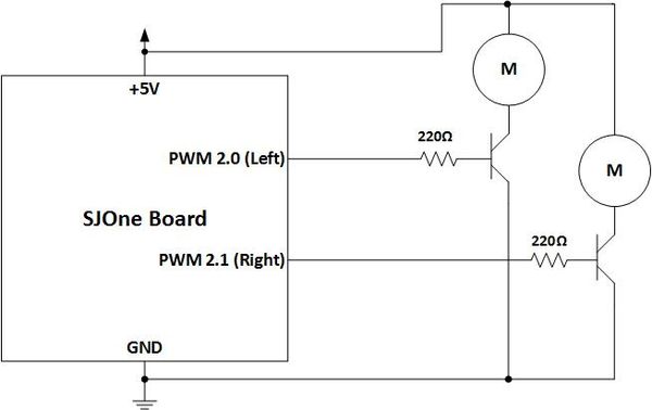
We chose a simple DC motors for our RC car. In order to use the PWM API provided by our Eclipse environment, we constructed a transistor circuit shown above. Doing so allowed us to control the speed of each individual motor, allowing more control for steering. The motors on the RC car will adjust depending on the levels of reflectivity from the IR receivers.
Hardware Interface
- Analog Digital Converter (ADC)
For this project, we utilized 6 analog IR emitter/receiver pair sensors. Because they were analog sensors, couldn't have connected these sensors directly to any GPIO pins, but needed to connect them to the ADC pins. Because we had more sensors than available ADC pins, we used an analog multiplexer to hold multiple analog inputs, and connected the common output a single ADC pin.
- Serial Peripheral Interface (SPI)
In order to implement the lane changing feature, we thought it was be best to send a signal from a separate SJone board through the Nordic wireless. One board acted as a transmitter and one board, the one that was connected to the RC car, acted as the receiver.
- General Purpose Input Ouput (GPIO)
Because we used 6 analog sensors while our board only had 3 available ADC pins, we needed to use a digitally controlled analog multiplexer. We fed the outputs of the sensors as inputs to the multiplexer. The single, common output of the multiplexer was connected to the ADC pin as explained earlier. In order to control which sensor value passed through the MUX, we needed to change the control signals of the MUX. Because this was a digitally controlled MUX, we initialized 3 GPIO pins to act as the control signals.
Another utilization of GPIO pins was for the PWM signals. In order to control the motors, we contructed the circuit described in the hardware design section. We then used the PWM API provided to us in order to control the speed of each motor.
The last way we used GPIO pins was from the transmitter board. When changing lanes, we had the transmitter board send a character over Nordic wireless once one of the on-board switches was pressed. Depending on the switch, a certain character was sent to the RC car which would then execute either a left or right turn once received.
Software Design
Show your software design. For example, if you are designing an MP3 Player, show the tasks that you are using, and what they are doing at a high level. Do not show the details of the code. For example, do not show exact code, but you may show psuedocode and fragments of code. Keep in mind that you are showing DESIGN of your software, not the inner workings of it.
SHOW FLOWCHARTS OF IR SENSING / PWM MOTOR CONTROL
SHOW FLOWCHART OF WIRELESS?
Implementation
This section includes implementation, but again, not the details, just the high level. For example, you can list the steps it takes to communicate over a sensor, or the steps needed to write a page of memory onto SPI Flash. You can include sub-sections for each of your component implementation.
Testing & Technical Challenges
Issue #1
The first issue we came across was the ADC converters. For our design, we decided to use 6 analog IR sensors, used to detect lane markers on the road. After looking at the board's schematic, we realized only 3 ADC pins were available to us. After doing some research, we found an IC that solved our issue: MC14051, an analog multiplexer. This multiplexer allowed up to 8 analog inputs, which was more than enough for the amount of sensors we had. What also made this multiplexer a good fix was that the control pins were digitally controlled, allowing us to configure GPIO pins from the SJOne board for the control inputs to the analog multiplexer.
Issue #2
Discuss the original sensor layout and how it posed a problem.
Issue #3
Discuss conditions when no lane was detected.
Fixed with static int flag. (go in depth later)
Issue #4
Discuss how both motors reacted differently to different values (one weaker than the other)
Conclusion
Conclude your project here. You can recap your testing and problems. You should address the "so what" part here to indicate what you ultimately learnt from this project. How has this project increased your knowledge?
Project Video
Demo 1: https://www.youtube.com/watch?v=tN-m2zH6Z08&feature=youtu.be
Project Source Code
References
Acknowledgement
- We would like to thank Preet for giving his time to teach us the fundamentals and applications of embedded systems, and giving us the opportunity to create our first embedded project. You've definitely inspired us to pursue a career in embedded systems.
- We would also like to thank Dr. Ozemek for teaching us the fundamentals of embedded systems, and giving us the inspiration to change our lifestyles.
References Used
List any references used in project.
Controlling DC Motors Using PWM
Appendix
You can list the references you used.


