Difference between revisions of "F12: Evil Watchdog"
Waymond f12 (talk | contribs) (→Motion Sensor) |
Waymond f12 (talk | contribs) (→Motion Sensor) |
||
| Line 364: | Line 364: | ||
=== Motion Sensor === | === Motion Sensor === | ||
| − | Prior to any connections to the Motion sensor, it was first tested with a power supply and a multi-meter. When testing everything, it showed that the sensor is vary sensitive to any movement made. Another thing that was noticed was that the higher the voltage applied, the more distance the motion sensor covers when detecting motion. The last thing that was discovered while testing was the amount of time the acknowledgment of motion is on. It turns out that the Alarm signal stays low, when detecting motion, for about 3 seconds until it reaches high again. | + | Prior to any connections to the Motion sensor and Microcontroller, it was first tested with a power supply and a multi-meter. When testing everything, it showed that the sensor is vary sensitive to any movement made. Another thing that was noticed was that the higher the voltage applied, the more distance the motion sensor covers when detecting motion. The last thing that was discovered while testing was the amount of time the acknowledgment of motion is on. It turns out that the Alarm signal stays low, when detecting motion, for about 3 seconds until it reaches high again. |
=== Alarm === | === Alarm === | ||
Revision as of 06:42, 18 December 2012
Contents
Abstract
The Evil Watchdog takes the responsibilities of a pet guarding a house. It will roam around a predefined environment, navigate around obstacles, and sound an alarm whenever foreign motion is detected. Although it cannot express love, it will not make a mess.Introduction
The objective of this project is to design a vehicle to imitate a guard dog. The following items will be incorporated to accomplish this goal :
- Motor driven chassis
- Vehicle will move in a random path detecting motion
- Vehicle will sound an alarm when motion is detected
Technology used
- Motion sensor
- Distance sensor
Team Members and Roles & Responsibilities
- Waymond Chen: Front motor control and distance sensor programming
- Hung Vuong: Distance and motion sensor programming
- Erik Montoya: Backside motor control and programming
Schedule
| Starting | Ending | Planned Activities | Actual |
|---|---|---|---|
| Oct 26, 2012 | Nov 1, 2012 |
|
|
| Nov 2, 2012 | Nov 8, 2012 |
|
|
| Nov 9, 2012 | Nov 15, 2012 |
|
|
| Nov 16, 2012 | Nov 22, 2012 |
|
|
| Nov 23, 2012 | Nov 29, 2012 |
|
|
| Nov 30, 2012 | Dec 6, 2012 |
|
|
| Dec 7, 2012 | Dec 13, 2012 |
|
|
| Dec 19, 2012 | Dec 19, 2012 |
|
Parts List and Costs
| Item | Details | Source | Cost Ea. | Qty. | Total |
|---|---|---|---|---|---|
| Batteries | Duracell 1.5V Size AA | Costco | $1.33 | x5 | $6.65 |
| Distance Sensors | SRF02 Ultrasonic Range Finder | Preet Kang | $25.00 | x3 | $75.00 |
| LEDs | Blue and Green LEDs | HSC Electronics | $0.35 | x2 | $0.70 |
| Microcontroller | ARM7 NXP LPC2148 | Preet Kang | $60.00 | x1 | $60.00 |
| Motion Sensor | PIR Motion Sensor SEN-08630 | Preet Kang | $9.95 | x1 | $9.95 |
| Motor Controllers | SJValley Engineering 5A Motor Controller | Dr. Özemek | $17.99 | x2 | $35.98 |
| Piezo Buzzer | 75dB 6VDC Piezo Buzzer | RadioShack | $3.89 | x1 | $3.89 |
| RC Car | New Bright Land Rover Mud Slinger | Fry's Electronics | $15.34 | x1 | $15.34 |
| Voltage Regulator | LM7805CV Voltage Regulator | HSC Electronics | $2.00 | x1 | $2.00 |
Design and Implementation
Hardware Design
Frame and Inner Placement
For convenience, a New Bright toy RC car was purchased and disassembled. The motors and wheels were already pre-mounted onto the chassis, allowing electronic parts to control the car. On the chassis, slots above the wheel wells were large enough to house motor controllers while the center of the chassis provided enough room to include a small breadboard and the microcontroller. All wires were shortened to the shortest length possible to reduce clutter.Sensor Placement
The sensors, which guided car control, were strategically mounted in front and above the car. This increased visibility of the sensors. Three distance sensors were used to detect obstacles: a left-, a center-, and a right-side sensor was used to determine steering of the vehicle. A front-mounted sensor would seek motion as the car was stopped. Should motion be seen, the piezo buzzer sitting at the front of the car would promptly be sounded.
Power Supply
The battery box beneath the car provided additional convenience. It housed five 1.5-volt AA batteries that supplied up to 7.5 volts in series. This power supply provided enough power to run all of the components of this project. Whenever existing batteries began to run low on power, new batteries could be swapped into place easily. The following list describes the power requirements of each part used:
| Part | Voltage Range | Source |
|---|---|---|
| Distance Sensors (Parallel) | +5V | Microcontroller Pin |
| LPC2148 Microcontroller | +7V to +20V | Battery Pack |
| Motion Sensors | +5V to +12V | Battery Pack |
| Motor Controllers | +7V to +30V | Battery Pack |
| Piezo Buzzer | +3V to +6V | Microcontroller Pin |
Hardware Implementation
Motion Sensor
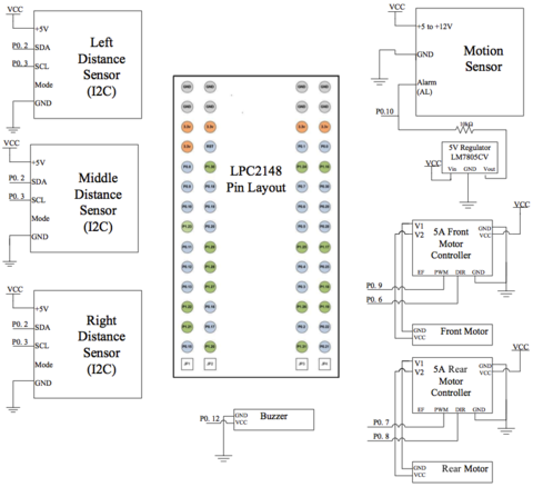
This Passive Infrared (PIR) Motion Sensor measures changes in heat as an indicator. This Sensor actually signals the pin low when it detects one of these changes. The motion sensor is actually less complicated then what it seems. Three pins are needed in order to have a functional sensor. The Red wire is voltage source, the brown wire is ground, and the black wire is the alarm signal. The alarm signal can be connected to any pin on the Microcontroller that can handle a GPIO function. In addiction to this, you will also need to apply a pull up resistor on the pin. The pull up resistor is required because the sensor alarm pin is an open collector. Without this resistor, the value of the Alarm will just fluctuate between Low and High constantly.
| Microcontroller | Motion Sensor |
|---|---|
| VCC (7.5v) | VCC (7.5v) |
| GND | GND |
| P0.10 | Alarm (AL) |
Distance Sensor
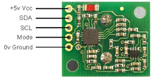
The SRF02 Ultrasonic range finder (distance sensor) can operate using Serial Mode or I2C mode. This device has a total of five pins: +5v VCC, SDA, SCL, Mode, and 0v Ground. Since the I2C mode is used, the mode pin doesn’t need to connect to anything. The SCL and SDA lines are connected to the pins that support SCL0 and SDA0 on the Microcontroller. These pins also need a pair of resistors because I2C is an Open Collector.
| Microcontroller | Distance Sensor |
|---|---|
| VCC (7.5v) | VCC (7.5v) |
| P0.2 | SDA |
| P0.3 | SCL |
| GND | GND |
5A Motor Controller
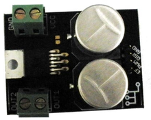
The Motor Controller is needed in order to be able to adjust speed on the motors. This specific controller maintains a continuous 5A current when applying 7 – 30 V. To interface to this device it only requires three pins: PWM, Direction, and Ground. An initiation of the pin needed to be done and activated as a PWM function on a pin and GPIO on another for direction.
| Microcontroller | Front Motor Controller |
|---|---|
| VCC (7.5v) | VCC (7.5v) |
| P0.9 | PWM |
| P0.6 | DIR |
| GND | GND |
| Microcontroller | Rear Motor Controller |
|---|---|
| VCC (7.5v) | VCC (7.5v) |
| P0.7 | PWM |
| P0.8 | DIR |
| GND | GND |
Software Design
FreeRTOS, a real-time operating system, was used to program the hardware used on the vehicle. FreeRTOS mainly uses C while allowing for some expansion into C++. Its support for tasks and semaphores made it a convenient platform for writing and implementing software for this project. Furthermore, FreeRTOS requires a small amount of memory while running tasks quickly and efficiently.
Several labs built using FreeRTOS were completed prior to starting this project, which contributed to a good understanding of the FreeRTOS system. The basic coding structure used for the labs also served as the basic coding framework for the Evil Watchdog.
Once all the necessary parts were collected, each part received its own dedicated piece of code and its own testing before becoming integrated with the other parts used for the car. Intuitively, the motor controllers were selected as the first parts for writing code, because the vehicle's movement depended entirely on the motors and wheels. Each motor controller can regulate the speed at which the attached wheels spin, through the use of pulse-width modulation (PWM). Looking at the car, only the rear wheels need speed control. It was not necessary to implement PWM on the front wheels because those wheels are used for steering and simply require steering extreme left, extreme right, or straight, thanks to the car's small size. The rear wheels were controlled through PWM, and the front wheels through GPIO.
FIXME: Add PWM.
The distance sensors were designed for use on the I2C or serial buses. Based on pin availability and software convenience, I2C was used to gather distance information from the sensors. The next question was: How would the microcontroller distinguish between the three sensors? A glance at the technical specifications provided the solution. Each sensor was equipped with a handy LED that flashed its address in a recognizable sequence. By comparing the sequence emitted, a programmer could determine the sensor's set address. Also, its address could be altered to allow the I2C to accommodate additional sensors, though each sensor must be programmed individually, one at a time. The sensors allow addresses ranging from 0xE0 to 0xFE, in increments of hex 2. For convenience, the following addresses were selected for the sensors: 0xE2 for the left sensor, 0xE4 for the center, and 0xE6 for the right.
Software Implementation
Motion Sensor
The coding of the sensor was not difficult at all. An initiation of the pin needed to be done and activated as a GPIO function. A function is designed to take multiple samples of the sensor to detect if a motion was actually detected and not some sort of glitch. Since the Sensor is highly sensitive, we have to take the samples while the back motor is not running.
Testing
Motor Controllers
The motor controllers were the first components to run through testing after the PWM driver was written. At first, the assumption was that a frequency of zero meant a full stop. That became untrue as the dog tried to run away at full speed even after the program shouted zero hertz. Once it was realized that higher frequency meant slower motion, the rear controller was successfully configured. The front motor was tested too. The main difficulty was in mapping out the voltage levels and voltage directions to see whether they corresponded to left, right, or center steering. Using LEDs helped figure out the mappings. An interesting point to note is that to return to center steering via GPIO, a change in steering direction must take place.
Distance Sensors
Prior to implementation, the distance sensors were placed on a breadboard to verify the accuracy of their readings. The sensors featured measurements at the centimeter level, allowing for more detailed integer readings compared to readings in inches. During testing, a tape measure was used to confirm sensor measurements. The error found was no more than 3-5% at distances up to 250 cm, which showed that the sensors were highly reliable for providing the vehicle's sight.
Motion Sensor
Prior to any connections to the Motion sensor and Microcontroller, it was first tested with a power supply and a multi-meter. When testing everything, it showed that the sensor is vary sensitive to any movement made. Another thing that was noticed was that the higher the voltage applied, the more distance the motion sensor covers when detecting motion. The last thing that was discovered while testing was the amount of time the acknowledgment of motion is on. It turns out that the Alarm signal stays low, when detecting motion, for about 3 seconds until it reaches high again.
Alarm
Because the alarm worked with different voltages, it was tested on a voltage generator before being placed in the car. 3.3 volts was enough to supply an audible tone.
The Entire Dog
Once all the components were stitched and strapped onto the dog, the canine was released into the wild (the Engineering building hallways). It ran freely and occasionally bumped into walls. The distance sensor thresholds were modified to allow extra space between the dog and its nearest obstacles. At one point, steering froze for no apparent reason. A close examination revealed that super glue holding the distance sensor posts had dripped onto the front axle, preventing the dog from making turns.
Technical Challenges
Battery Life
By far, the battery pack is the most vulnerable component in keeping the Evil Watchdog alive. Only five 1.5-volt AA batteries power the entire system. Possible solutions to this problem are to either use batteries with longer lifespans or to use rechargeable batteries to avoid wasting single-use cells. During testing, a variable-voltage DC power supply, grabbing power from a wall outlet, was used to power the project. This saved battery power later needed for demoing.
Check Opposites
When working with registers, double-check the code to see whether logic is written properly. Using IOSET and IOCLR, for instance, may seem easy and straightforward. However, they can easily become mixed up when a boolean checker is thrown into the mix. At one point during testing, the alarm rang when motion was sighted, and continued to ring forever. The suspect was an IOSET assignment that was instead supposed to be IOCLR. Once that was repaired, the dog ran happily again.
Distance Sensor Placement
Keep the side distance sensors pointing 45 degrees away from center sensor instead of perpendicular to it. Suggested by Preet, this allows the car to see more of its path ahead while maintaining some peripheral vision.
Motion Sensor Polling
The motion sensor is highly sensitive. It can detect slight movements in its environment. To avoid false alarms, modify the program to force the motion sensor to detect continuous movement before it decides to ring the alarm. By doing so, the system will ignore sudden movements assumed non-dangerous.
Vehicle Weight
The original toy car was designed to carry a lightweight circuit board that received RF signals to control the motors. When the car is torn apart and new components are added for this project, the amount of weight placed on the wheels rapidly increases. Additional weight requires extra torque from the wheels to move the carried load, which can drain the batteries much more quickly. The best way to alleviate this problem is to eliminate excess weight and to select the lightest available parts to be placed on the vehicle.
Conclusion
References
Thanks To...
- Dr. Haluk Özemek: Lecturer
- Preet Kang: Lab Instructor
Appendix
- Project source code is available at SourceForge
- Project Video: (FIXME)


