Difference between revisions of "F15: Car Report"
Proj user18 (talk | contribs) (→Project Title) |
Proj user18 (talk | contribs) (→Conclusion) |
||
| Line 278: | Line 278: | ||
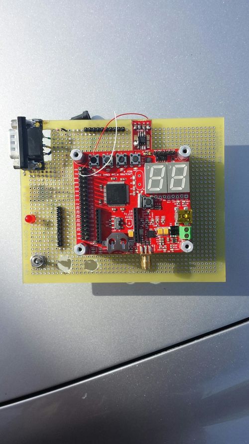
Starting this project, we didn't have much knowledge in the CAN Bus protocol. This project has extremely increased our knowledge in CAN bus Protocol and application of the OBD-II device. After the completing this project, we learned how the CAN Bus protocol works, what's in the hardware implementation for an OBD-II device, and how to write drivers for the CAN Bus protocol. Figure 8 displays the final design of our OBD-II. We learned how the information is transmitted and received to capture real-time data of a vehicle. We gain more insight how the car system connects over the CAN Bus protocol through the OBD-II to DB-9 cable to the transceiver and CAN controller. Also, we learned how important an OBD-II device is and how it is used be many different people for similar purpose. | Starting this project, we didn't have much knowledge in the CAN Bus protocol. This project has extremely increased our knowledge in CAN bus Protocol and application of the OBD-II device. After the completing this project, we learned how the CAN Bus protocol works, what's in the hardware implementation for an OBD-II device, and how to write drivers for the CAN Bus protocol. Figure 8 displays the final design of our OBD-II. We learned how the information is transmitted and received to capture real-time data of a vehicle. We gain more insight how the car system connects over the CAN Bus protocol through the OBD-II to DB-9 cable to the transceiver and CAN controller. Also, we learned how important an OBD-II device is and how it is used be many different people for similar purpose. | ||
| − | In the future, we would like to work more on this project to enhance the application of the CAN Bus protocol | + | In the future, we would like to work more on this project to enhance the application of the CAN Bus protocol. We would like to be able to transmit and receive more information from the vehicle and add additional features when transmitting and receiving. We are planning to incorporate and enhance this project into other projects that we will be working on in future classes. We look forward to working on this project in the future and build on it for other projects that we will be completing in the future. |
[[File: CMPE146_F15_CarReport_FinalDesign.jpg|500px|thumb|centre|Figure 8. Final Design.]] | [[File: CMPE146_F15_CarReport_FinalDesign.jpg|500px|thumb|centre|Figure 8. Final Design.]] | ||
Revision as of 22:01, 18 December 2015
Contents
Grading Criteria
- How well is Software & Hardware Design described?
- How well can this report be used to reproduce this project?
- Code Quality
- Overall Report Quality:
- Software Block Diagrams
- Hardware Block Diagrams
- Schematic Quality
- Quality of technical challenges and solutions adopted.
Project Title
Car Project: OBD-II Design over CAN BUS Protocol
Abstract
For our project, we will be building an OBD II device that will interface with a vehicle through CAN Bus protocol. OBD II stands for On-Board Diagnostic II, which is used to track and monitor a vehicle's status and functions. A OBD-II to DB-9 cable, transceiver, and CAN Controller on the SJ One Board were used to connect our device to the car's system in order to record real-time information of the vehicle like the temperature, engine check, and MPH. After gathering all required information, you can diagnose any faults in the vehicle that may appear.
Objectives & Introduction
A device like OBD-II was introduced to the automobile industry in the late 1970's and it is still widely used today as a diagnostic tool for a vehicle from engine control to parts records. OBD-II is used by mechanics, car owners, agencies, and car manufactures to ensure vehicle is within the EPA emission standards. The car system responds, accepts, and implements an OBD-II interface through the CAN Communication. The CAN communication is used widely in the automotive industry due to its very deterministic and reliable connection to guarantee that a message will be transmitted, received, and executes. All controls in a car is transported on the CAN Bus protocol. The CAN communication is a broadcast bus that has baud rates of 100K, 125K, 250K, 500K, or 1M per second. The CAN communication is half duplex that transmits and receives a signal at a time with a differential pair. The differential pair is used for better noise limitation over long distances. As California has become one of the leading states for the car industry, we decided building an OBD-II will lead to a better understanding of CAN Bus interface that is widely used in the car industry.
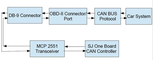
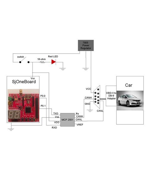
To design a OBD-II, we used a voltage regulator, switching circuit, transceiver, OBD-II to DB-9 cable, DB-9 connector, and the CAN controller on the SJ One board. We used CAN interface to transmit and receive information regarding the vehicle. The OBD-II to DB-9 cable used to connect from the car system through the OBD-II port to the CAN Controller on our SJ One Board doesn't accept CAN voltage levels so we need to convert the CAN signals to logical signals through a MCP2551 transceiver. The transceiver permits the CAN interface between our CAN controller and the OBD-II. The voltage regulator allows the longer distance connection by increasing the voltage levels. The objective of this project is to design an OBD-II device that connects to a car system over CAN communication to establish strong and reliable connection to gather valid and real-time information like MPH, RPM, engine check, temperature, car performance, and any faults. A simple flowchart regarding the overview of how the system is connected is shown in Figure 1.
Team Members & Responsibilities
- Yasmine Jamjoum
- Hardware Design and Software Implementation of CAN Bus
- Khang Doan
- Hardware Design and Software Implementation of CAN Bus
Schedule
| Week# | Date | Planned Task | Actual |
|---|---|---|---|
| 1 | 10/12-10/18 |
• Purchase all required parts • Download and install programs and data sheets for CAN Bus interface and OBD-II connection |
• Parts ordered on 10/16 • All required programs and data sheets were downloaded and installed • Began researching information on OBD-II devices and CAN BUS Protocol |
| 2 | 10/19-10/25 |
• Gather all parts • Test all components separately • Plan and design hardware design diagrams |
• Testing components separately was successful • Waiting on a few components • Diagrams for hardware design were complete |
| 3 | 10/26-11/1 |
• Begin hardware design • Test the hardware design along the way |
• Started hardware design • Started project report |
| 4 | 11/2-11/8 |
• Complete the hardware design • Test the hardware as a whole |
• Realized we needed more hardware components • Waiting on the components before we can continue with the hardware design completion • Continued researching about the hardware and software interface for OBD-II over CAN BUS Protocol |
| 5 | 11/9-11/15 |
• Complete the hardware design • Test the complete hardware connection • Continue researching about the hardware and software interface for OBD-II over CAN BUS Protocol
|
• Received the transceiver • Completed the hardware design • Updated all hardware diagrams • Tested and Debugged the whole system • Continued researching about the hardware and software interface for OBD-II over CAN BUS Protocol |
| 6 | 11/16-11/22 |
• Begin the software interface for OBD-II over CAN BUS protocol
|
• Started the software interface for OBD-II over CAN BUS protocol • Continued researching about the hardware and software interface for OBD-II over CAN BUS Protocol • Obtained additional data sheets for CAN Bus and OBD-II connection |
| 7 | 11/23-11/29 |
• Continue the software interface for OBD-II over CAN BUS protocol |
• Continued software programming for CAN BUS Protocol |
| 8 | 11/30-12/6 |
• Complete the software interface for OBD-II over CAN BUS protocol • Begin Debugging • Begin interfacing the hardware with the software |
• Completed the software interface for OBD-II over CAN BUS protocol • Started interfacing the hardware with the software • Started Testing and Debugging
|
| 9 | 12/7-12/13 |
• Finish Debugging the software • Interface the hardware with software • Test system design |
• Completed the debugging phase of the software • Completed interfacing the hardware with the software • Tested the device on an actual vehicle • Replaced hardware component to fix hardware connection • Continued the project report |
| 10 | 12/14-12/17 |
• Complete system testing • Complete the project report • Demo the project |
• Completed system testing • Created video for presentation • Completed the project report • Presented the project on Thursday, December 17, 2015 |
Parts List & Cost
Hardware
• OBD-II to DB-9 Cable [$9.95]
• Prototype board [$12.99]
• DB-9 Male Connector, Switch, LED, resistor, LM7805 voltage regulator [$10.99]
• LCD Display [$34.99]
• SJ One Board [$80.00]
• Vehicle: 2004 Acura TL [$10,100]
Software
• Windows Vista/7 (32 or 64-bit)
• Eclipse IDE
Design & Implementation
Hardware Design
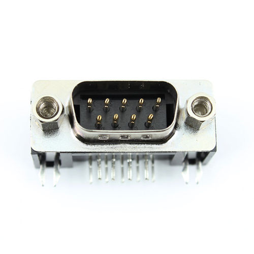
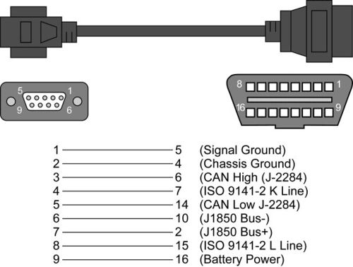
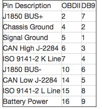
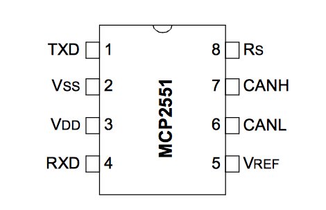
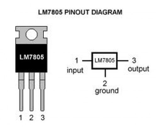
The ODB-II hardware design included a battery supply, voltage regulator, switch circuit, MCP 2551 transceiver, a DB-9 connector as shown in Figure 2, and a OBD-II to DB-9 cable that connects to the car. The OBD-II system can be found in cars manufactured in the year 1996 and later. The OBD-II device reveals the car's status such as temperature, MPH, and error faults. The OBD-II to DB-9 cable, as shown is Figure 3, is used to connect a vehicle's system to receive information over the CAN Bus. The pin diagram of the OBD-II to DB-9 connector is shown as Figure 4. However, this cable cannot convert CAN voltage signals to logical signals, so we used a MCP2551 transceiver. This transceiver will produce logical signals that the microcontroller on our SJ One Board can fully understand and implement from the OBD-II port.The purpose of the transceiver is to interface the CAN protocol and the actual physical bus. The transceiver allows a suitable signal to be transmitted over the CAN bus protocol. The pins of the transceiver are connected to the SJ One Board along with voltage and common ground. The pin diagram of the transceiver is shown as Figure 5. The CAN Bus pins from the DB-9 connector are connected to the CAN H and CAN L of the transceiver. The transceiver's Rxd and Txd pins are connected to the Td and Rd pins on the SJ One Board along with the voltage and common ground. The switch circuit is used to enable and disable the whole system along with a red LED to alert the user the system is activated. A voltage regulator is used to stabilize the voltage at a certain level going through the circuit that is shown as Figure 6 along with the pin diagram. We needed to increase the voltage level to deliver the system over long distances.
Hardware Interface
To implement this project, we used CAN Bus Protocol with a CAN High and CAN Low signals. CAN Bus Protocol is a reliable broadcasting bus that uses two wires for transmitting receiving. One signal is activated at a time with differential pairs where one wire does a certain function and the corresponding wire does the opposite operation. The CAN Bus Protocol has a 120-Ohm capacitor at the ends of the CAN Bus to prevent any signal reflection. The car system is connected from the OBD-II port of the car to our project through an OBD-II to DB-9 cable over CAN Bus protocol. The CAN High and CAN Low pins of the DB-9, which are pins 7 and 2, are connected to the transceiver's CAN High and CAN Low. The wires connected the CAN High and CAN Low are twisted together to reduce noise. The Rxd and Txd pins of the transceiver are connected to the Td and Rd pins on the SJ One Board, which are pins P0.0 and P0.1, where we have a CAN controller. The CAN transceiver makes the Txd or Rxd pins a single differential pair wire that is on the CAN BUS. Pin VDD of the transceiver is connected to the Vcc from the SJ One Board and pin Vss of the transceiver is connected to common ground. The voltage regulator is connected to the Vcc of the DB-9 connector, common ground, and the switch circuit. The switch circuit is used to enable the whole system and the voltage regulator is used to adjust the voltage levels to interface over long distances. Drivers were written to drive the CAN Bus protocol in order for information from the car to be transmitted and received. The ODB-II port from the car along with the connection of the OBD-II to DB-9 cable will connect the car system to transmit and receive information regarding the vehicle's status and any faults over CAN communication.
Software Design
//ADD! half-duplex BUS, that operates using a pair of differential signals. Typically, the speed standards are 100K, 250K, 500K or 1Mbit. CAN Bus Frame, Message ID, Message ID design,
The CAN BUS continuously send out information throughout the network to every node. To listen to the broadcast from the CAN BUS, we have to decide on which message to filter out. Each message from the CAN BUS has a very specific parameter ID (PID). For example engine RPM would have a PID hexadecimal value of 0x0C. Another thing to notice is the lower the hexadecimal value would have the higher priority. This is another characteristic of the CAN BUS protocol. To first establish communication on the CAN BUS, we first turn off all filter to insure our hardware and software are working correctly. After ensuring our hardware and software work, we look at what PID we are interested in, we begin to filter out the unwanted messages. After storing our wanted messages in a buffer, we start to process the raw data. We translates these data into something that is understandable based on a formula.
Implementation
Our first step in implementing our design is to initialized all port, baudrate and which CAN we are using (CAN1/CAN2). In addition, we also have to set up the Rx and Tx queue size. This is done through the init function in the CAN API. Next, we have to ensure our hardware is working correctly by accepting all messages on the CAN BUS. We got to be careful not to overwhelm our buffer. After successfully receiving messages from the bus, we begin to look for what PID we are interested in. After setting up the filter, we store all of our wanted messages for later processing. Since the data we are receiving are hexadecimal values, we use a formula to translated this data into something understandable. We then output this data into the console.
Testing & Technical Challenges
The testing phase for our project was very time consuming since an actual car was required for every testing procedure. We had to constantly go back and forth to our workstation and the parking lot. First, we begin the testing phase by testing our hardware circuitry to ensure there weren't any short circuits. Next, we developed the drivers for the OBD-II and Can Bus implementation. Once the hardware and software were complete, it was time to interface the CAN Bus protocol to the car system. We faced difficulties communicating over the CAN Bus protocol but after further research, we were able to communicate to the car system over CAN communication. The advise we would give someone if he or she started our project from scratch is try to get help from peers that have experience in CAN Bus Protocol. When we ran into problems, we didn't have anyone to turn to for advise or help. After identifying the problems, we had to do further research issues resolving the problems without any feedback from any person with experience in CAN communication. Another piece of advise we would give is allocate a lot of time for debugging. This project requires most of the time for debugging purpose to implement CAN communication to the car's system to gather the real-time information from the vehicle.
Issue #1
Our first issue we faced was that the parts took awhile to come in from the manufacturers. Our resolution was to begin researching and try to learn as much as possible about the hardware implementation and CAN communication.
Issue #2
Our second issue was that we had difficult understanding and implementing the CAN Bus protocol. We had trouble transmitting or receiving information from the car. We continued researching on the CAN Bus protocol and we analyzed the drivers. After very long hours of research and close analyzation, we were able to enable the CAN communication from the car system to our CAN controller on the SJ One Board.
Issue #3
Every time we plugged the OBD-II into the vehicle and ran the software, the voltage regulator became extremely hot and the transceiver started smoking. We tested different points in the hardware when we realized that the voltage wasn't correct. Our resolution was to change the voltage regulator to a new a voltage regulator. After we swapped the voltage regulator, the voltage level were correct.
Conclusion
Starting this project, we didn't have much knowledge in the CAN Bus protocol. This project has extremely increased our knowledge in CAN bus Protocol and application of the OBD-II device. After the completing this project, we learned how the CAN Bus protocol works, what's in the hardware implementation for an OBD-II device, and how to write drivers for the CAN Bus protocol. Figure 8 displays the final design of our OBD-II. We learned how the information is transmitted and received to capture real-time data of a vehicle. We gain more insight how the car system connects over the CAN Bus protocol through the OBD-II to DB-9 cable to the transceiver and CAN controller. Also, we learned how important an OBD-II device is and how it is used be many different people for similar purpose.
In the future, we would like to work more on this project to enhance the application of the CAN Bus protocol. We would like to be able to transmit and receive more information from the vehicle and add additional features when transmitting and receiving. We are planning to incorporate and enhance this project into other projects that we will be working on in future classes. We look forward to working on this project in the future and build on it for other projects that we will be completing in the future.
Project Video
Project Source Code
References
Acknowledgement
We would like to thank the following people for their contributions during this project:
Preet Kang
References Used
Introduction to CAN Hacking
http://hackaday.com/2013/10/21/can-hacking-introductions/
Introduction to CAN Protocols
http://hackaday.com/2013/10/29/can-hacking-protocols/
Hacking into Vehicle
http://fabiobaltieri.com/2013/07/23/hacking-into-a-vehicle-can-bus-toyothack-and-socketcan/
Appendix
OBD-II to DB9 Cable
https://www.sparkfun.com/products/10087
LPC1759 Datasheet
http://www.nxp.com/documents/data_sheet/LPC1759_58_56_54_52_51.pdf
LPC176x/5x User manual
http://www.nxp.com/documents/user_manual/UM10360.pdf
MCP 2551 Transceiver
http://www.electroschematics.com/wp-content/uploads/2015/07/MCP2551-datasheet.pdf
