Difference between revisions of "S14: Wireless Control Car"
Proj user14 (talk | contribs) (→Hardware Interface) |
Proj user14 (talk | contribs) (→Conclusion) |
||
| (41 intermediate revisions by 2 users not shown) | |||
| Line 1: | Line 1: | ||
| − | |||
| − | |||
| − | |||
| − | |||
| − | |||
| − | |||
| − | |||
| − | |||
| − | |||
| − | |||
| − | |||
| − | |||
== Project Title == | == Project Title == | ||
Wireless Control Car | Wireless Control Car | ||
== Abstract == | == Abstract == | ||
| − | This project is about the development of a robotic car which can be controlled wirelessly. A robotic car has two front and back motors which are controlled independently. Both the motors are attached to a wireless module in built in the microcontroller so that it can be controlled wirelessly. This car also has | + | This project is about the development of a robotic car which can be controlled wirelessly. A robotic car has two front and back motors which are controlled independently. Both the motors are attached to a wireless module in built in the microcontroller so that it can be controlled wirelessly. This car also has an ultrasonic sensors which is attached to the front of the car. The sensor helps in avoiding any collision with the obstacle. This car also has an auto mode which enables the car to run without the user's help. |
== Objectives & Introduction == | == Objectives & Introduction == | ||
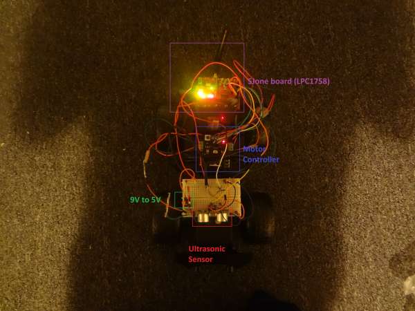
| − | The objective of this project is to build a wireless robotic car | + | The objective of this project is to build a wireless robotic car. This car has two DC motors to control front and back wheels, an H bridge dual motor controller to control the speed and direction of the motor, a ultrasonic sensors for obstacle avoidance, an Accelerometer sensor to detect the direction of board rotation and a wireless module to control the car wirelessly. |
| + | |||
| + | [[File:CmpE244_S14_Car.jpg]] | ||
| + | |||
| + | [[File:CmpE244_S14_Toy_car.jpg]] [[File:CmpE244_S14_Front_motor.jpg]] | ||
| + | |||
| + | [[File:CmpE244_S14_Back_motor.jpg]] | ||
| + | |||
| + | |||
The project is divided into following objectives: | The project is divided into following objectives: | ||
* Design the circuit and algorithm for motor controller to control both front and back motor independently. | * Design the circuit and algorithm for motor controller to control both front and back motor independently. | ||
| − | * Write the driver to control | + | * Write the driver to control inbuilt accelerometer sensor on the microcontroller. |
* Write the wireless driver to send and receive commands between two microcontroller boards. | * Write the wireless driver to send and receive commands between two microcontroller boards. | ||
| Line 41: | Line 37: | ||
| 02/24 | | 02/24 | ||
| Project Planning | | Project Planning | ||
| − | | Completed | + | | Completed on Time |
|- | |- | ||
! scope="row"| 1 | ! scope="row"| 1 | ||
| 03/06 | | 03/06 | ||
| Order Parts | | Order Parts | ||
| − | | Completed | + | | Completed on Time |
|- | |- | ||
! scope="row"| 1 | ! scope="row"| 1 | ||
| 03/10 | | 03/10 | ||
| Reviewing part's user manual and datasheet | | Reviewing part's user manual and datasheet | ||
| − | | Completed | + | | Completed on Time |
|- | |- | ||
! scope="row"| 3 | ! scope="row"| 3 | ||
| 03/24 | | 03/24 | ||
| PWM Driver | | PWM Driver | ||
| − | | Completed (04/6) | + | | Understanding PWM took more time than I was expecting. It's Completed on (04/6) |
|- | |- | ||
! scope="row"| 3 | ! scope="row"| 3 | ||
| 03/24 | | 03/24 | ||
| Wireless Driver | | Wireless Driver | ||
| − | | | + | | Completed on Time |
|- | |- | ||
! scope="row"| 3 | ! scope="row"| 3 | ||
| 04/1 | | 04/1 | ||
| Acceloremoter Driver | | Acceloremoter Driver | ||
| − | | | + | | Completed on Time |
|- | |- | ||
! scope="row"| 3 | ! scope="row"| 3 | ||
| 04/12 | | 04/12 | ||
| Design Integration | | Design Integration | ||
| − | | | + | | Completed on Time |
|- | |- | ||
! scope="row"| 2 | ! scope="row"| 2 | ||
| 04/14 | | 04/14 | ||
| Testing and Debug-Phase 1 | | Testing and Debug-Phase 1 | ||
| − | | | + | | Completed on Time |
|- | |- | ||
! scope="row"| 2 | ! scope="row"| 2 | ||
| 04/21 | | 04/21 | ||
| Testing and Debug-Phase 2 | | Testing and Debug-Phase 2 | ||
| − | | | + | | Partially Completed. Found some software bugs related to ultrasonic sensor that needs to be fixed. |
| + | |||
| + | Fixed the bug, but still more precise calculation of ultrasonic sensor data is needed. | ||
|- | |- | ||
! scope="row"| 1 | ! scope="row"| 1 | ||
| − | | 05/ | + | | 05/22 |
| Project Demo | | Project Demo | ||
| − | | | + | | Completed |
|} | |} | ||
| Line 99: | Line 97: | ||
|- | |- | ||
! scope="row"| 1 | ! scope="row"| 1 | ||
| − | | SJOne Board (LPC1758) | + | | SJOne Board (LPC1758)which include: Accelerometer sensor(MMA8452Q) and Nordic Wireless sensor(nRF24L01) |
| − | | One board from SJSU CmpE and one board by Preet | + | | One board from SJSU CmpE and one board by Preet |
| 2 | | 2 | ||
| $80.00 | | $80.00 | ||
| Line 109: | Line 107: | ||
| 1 | | 1 | ||
| $15.00 | | $15.00 | ||
| − | |- | + | |-Nordic Wireless sensor (nRF24L01 |
! scope="row"| 3 | ! scope="row"| 3 | ||
| − | | Ultrasonic Sensor | + | | Ultrasonic Sensor (HCSr04) |
| Amazone | | Amazone | ||
| 1 | | 1 | ||
| Line 117: | Line 115: | ||
|- | |- | ||
! scope="row"| 4 | ! scope="row"| 4 | ||
| − | | 9V Battery | + | | 9V-2000mAh Rechargeable Battery (Nickel-metal Hydride battery) |
| Frys | | Frys | ||
| 1 | | 1 | ||
| Line 127: | Line 125: | ||
| 1 | | 1 | ||
| $20:00 | | $20:00 | ||
| + | |- | ||
| + | ! scope="row"| 6 | ||
| + | | Motor Controller (L298 Dual H-Bridge DC Motor Controller) | ||
| + | | robotshop | ||
| + | | 1 | ||
| + | | $18:00 | ||
|- | |- | ||
! scope="row"| | ! scope="row"| | ||
| Line 132: | Line 136: | ||
| | | | ||
| | | | ||
| − | | $ | + | | $150:00 |
|- | |- | ||
|} | |} | ||
| Line 138: | Line 142: | ||
== Design & Implementation == | == Design & Implementation == | ||
=== Hardware Design === | === Hardware Design === | ||
| − | The hardware is designed by going through each project part's datasheet and LPC1758 microcontroller. After understanding the pin connections and the design, all the parts are connected by jumper wires. The Power to the microcontroller is supplied by USB cable which is spliced so that one end is connected to the 5V power supply. The Power source used for this project is rechargeable 9V battery, which is then connected to a power distribution circuit. A Power distribution circuit takes 9V from rechargeable battery converts to 5V. The Following block diagram shows the overall connection between the project parts: | + | The hardware is designed by going through each project part's datasheet and LPC1758 microcontroller. After understanding the pin connections and the design, all the parts are connected by jumper wires. The Power to the microcontroller is supplied by USB cable which is spliced so that one end is connected to the 5V power supply. The Power source used for this project is rechargeable 9V battery, which is then connected to a power distribution circuit. A Power distribution circuit takes 9V from rechargeable battery converts to 5V. |
| + | |||
| + | [[File:CmpE244_S14_SJone_board.jpg]] | ||
| + | |||
| + | |||
| + | The Following block diagram shows the overall connection between the project parts: | ||
[[File:CmpE244_S14_HWDesign.jpg]] | [[File:CmpE244_S14_HWDesign.jpg]] | ||
=== Hardware Interface === | === Hardware Interface === | ||
| − | The Transmitting | + | The Transmitting Module used the following interfaces: |
* I2C Bus | * I2C Bus | ||
** Used to read the board orientation from Accelerometer sensor | ** Used to read the board orientation from Accelerometer sensor | ||
* SPI Bus | * SPI Bus | ||
| − | ** Used to transmit commands from Nordic wireless | + | ** Used to transmit commands from Nordic wireless from receiving board |
* GPIO | * GPIO | ||
** Control Motor direction and speed, read ultrasonic sensor and Switches for start and stop | ** Control Motor direction and speed, read ultrasonic sensor and Switches for start and stop | ||
| + | |||
| + | |||
| + | |||
| + | The Receiving Module board used the following interfaces: | ||
| + | * SPI Bus | ||
| + | ** Used for receiving commands from a Nordic wireless from transmitting board | ||
| + | * GPIO | ||
| + | ** PWM interface for front and back motor | ||
| + | ** Direction control for front and back motor | ||
| + | ** Send Trigger to Ultrasonic sensor | ||
| + | ** Detect Echo back pulse from Ultrasonic sensor | ||
=== Software Design === | === Software Design === | ||
| − | + | The Software is implemented by following the below flowchart: | |
| + | |||
| + | '''Transmitting module''' | ||
| + | |||
| + | [[File:CmpE244_S14_TX2Flowchart.jpg]] | ||
| + | |||
| + | |||
| + | '''Receiving module''' | ||
| + | |||
| + | [[File:CmpE244_S14_RXFlowchart.jpg]] | ||
| + | |||
=== Implementation === | === Implementation === | ||
| − | + | ||
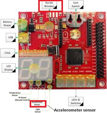
| + | '''Accelerometer sensor''' (Part: MMA8452Q, inbuilt in SJone board). | ||
| + | |||
| + | The direction of board tilt is calculated by reading the accelerometer sensor. To read the sensor data follow the following steps: | ||
| + | |||
| + | *Step1: Initialize accelerometer sensor | ||
| + | *:Set ''Ctrl1_reg''1 register's last bit to 0 to select standby mode. | ||
| + | *:Enable Portrait/Landscape status register through PL_Cfg register and set bit 4 in Ctrl_reg4 register. | ||
| + | *:set denounce counter to 100ms through PL_count register. | ||
| + | *:Set the sensor output data rate (100Mhz) and the ACTIVE mode from Ctrl1_reg1 register. | ||
| + | |||
| + | *Step2: Read Pl_status register from accelerometer sensor to get direction and orientation of the SJone board. | ||
| + | *:The following value will determine what direction or orientation the board is: | ||
| + | If bit[1:0] is: | ||
| + | 0: Portrait Up | ||
| + | 1: Portrait Down | ||
| + | 2: Landscape Right | ||
| + | 3: Landscape Left | ||
| + | |||
| + | If bit[0] is: | ||
| + | 0: Front facing orientation | ||
| + | 1: Back facing orientation | ||
| + | |||
| + | '''Motor Controller''' (L298 Dual H-Bridge DC Motor Controller). | ||
| + | ) | ||
| + | The dual Motor controller is used to control the speed and the direction of both front and back motor. Motor controller has one enable and two interrupts pins for each motor. | ||
| + | Follow the following steps to control the motors through motor controller: | ||
| + | *Step1: Initialize motor controller | ||
| + | *:initialize two PWM signal and then set it to 1KHz frequency in SJone board. | ||
| + | *:Configure the speed of the motor through PWM from LPC1758 data sheet. | ||
| + | *: I used the inbuilt function provided by the CmpE244 instructor. | ||
| + | ''PWM front_Motor.set(int percentage of motor speed)'' | ||
| + | The process of converting the percentage of speed is as follow: | ||
| + | If percent = 70, mTcMax = 1000, then value will be 70*1000 / 100 = 700 | ||
| + | After the calculation, you write these values to the MR memory locations based on which PWM is selected in SJone board. | ||
| + | : Set four GPIO pins for the four interrupt pins as output. | ||
| + | |||
| + | *Step2: Control the direction of motor (clock or anti clock) as following: | ||
| + | |||
| + | PWM Int1 Int2 Function | ||
| + | -------------------------------------------------------------- | ||
| + | High High Low Turn Anti-clockwise (Reverse) | ||
| + | High Low High Turn clockwise (Forward) | ||
| + | High High High Stop | ||
| + | High Low Low Stop | ||
| + | Low X X Stop | ||
| + | |||
| + | The back motor simply turns the wheels forward and backward. The front motor is attached to a toy car inbuilt mechanical system which turn wheels right when motor runs clockwise and turns left when motor runs anti clock wise. | ||
| + | |||
| + | |||
| + | '''Nordic Wireless sensor''' (nRF24L01, inbuilt in SJone board). | ||
| + | |||
| + | Nordic Wireless sensor is used to send and receive the data from one SJboard to other. I used the inbuilt wireless function to send and receive data packets. | ||
| + | |||
| + | Set the address: ''mesh_set_node_address(commander_addr)'' | ||
| + | Send data: ''wireless_send(car_addr,mesh_pkt_nack, &command,1,max_hops)'' | ||
| + | |||
| + | For this project I used following protocol: | ||
| + | car_addr=300 | ||
| + | commander_addr=400 | ||
| + | |||
| + | Function Command | ||
| + | move_forward : 1 | ||
| + | move_backward : 2 | ||
| + | move_right : 3 | ||
| + | move_left : 4 | ||
| + | stop : 5 | ||
| + | start : 10 | ||
| + | full_speed : 6 | ||
| + | half_speed : 7 | ||
| + | auto_pilot_on : 8 | ||
| + | auto_pilot_off : 9 | ||
| + | |||
| + | For receiving module, set the address: ''mesh_set_node_address(car_addr)'' and then read the data. | ||
| + | |||
| + | '''Ultrasonic sensor''' (Pasrt: HCSr04). | ||
| + | Ultrasonic sensor is used to detect if any object is in front of the car or not. The ultrasonic sensor has four pins. Two are power and ground pins and other two are Echo and Trigger pins. | ||
| + | Trigger pin tells ultrasonic sensor to start sending waves and echo pin assert from low to high if it receive a wave back. By calculating the time between sending and receiving the wave, we can calculate the distance between the reflected object. | ||
| + | |||
| + | The process of initializing ultrasonic sensor is as follows: | ||
| + | *Step1: initialize ultrasonic sensor. | ||
| + | *:Set Trigger pin as output | ||
| + | *:Set Echo pin as input | ||
| + | *:Set interrupt on Echo pin on falling edge (I used in built interrupt enable function for port 2 pins provided by the instructor). | ||
| + | |||
| + | *Step2: Take snapshot of the hardware time. I used timer1 function provided by FreeRTOS. | ||
| + | *Step3: Send High pulse for at least between 15us to 20us on the trigger pin and then send low pulse. | ||
| + | *Step4: Record the hardware time again as soon as a interrupt(falling edge) occur on the echo pin. | ||
| + | *Step5: Calculate the distance as following | ||
| + | *:TimeDelta = timerValueAtinterrupt - timerValueAtTrigger | ||
| + | *:Convert time from nanosecond to microsecond: TimeDelta = TimeDelta * 0.666. Since at Timer1, Each tick = 1/(48Mhz/32) = 666ns (more info on LPC1758 datasheet) | ||
| + | *:TimeDelta = TimeDelta - HoldoffTime (from ultrasonic sensor datasheet) | ||
| + | *:Convert calculate time to distance such as into centimetre: distance = TimeDelta /29; (This formula can be found in the ultrasonic sensor datasheet) | ||
| + | |||
| + | |||
| + | ''**The overall implementation of the whole project is explained in the above flow chart diagram.'' | ||
== Testing & Technical Challenges == | == Testing & Technical Challenges == | ||
| − | + | Testing of this project is done before and after complete project integration. The whole project is tested by printing the output values from each sensor's to the laptop's terminal screen for validation. | |
| − | |||
| − | + | '''Transmitting module:''' | |
| + | The software testing of transmitting module is done by printing the value from Accelerometer sensor and the command it sends from Nordic wireless sensor on the terminal screen. The SJone board has inbuilt accelerometer and wireless sensor, so it didn't need any hardware testing. | ||
| − | + | '''Receiving module:''' | |
| − | + | Receiving module is tested by printing the output value that it received from transmitting module and the value that it sends to the motor controller and the ultrasonic sensor. | |
| + | |||
| + | '''Ultrasonic sensor''' is tested by probing (by oscilloscope) on the trigger and echo pins on the ultrasonic sensor. It validated that the microcontroller is sending the trigger and the sensor is outputting the echo back pulse. The timer1 function provided with the code gives the precise timing result as compared to the inbuilt timing function (such as simple for loop). | ||
| + | |||
| + | '''Motor controller''' is tested by printing out the speed and the direction of motor value on the terminal screen. At first the motor didn't run because of low current supply, but after correct power supply it started to run. The interrupt pins needed to be set correctly to rotate the motor clock and anticlockwise. | ||
| + | |||
| + | '''Complete Project testing:''' | ||
| + | The whole project is tested by connecting everything together and then sending the command through a transmitting board to receiving board and observing its behavior. At first the controlling of car such as direction and speed control was difficult, but after increasing the speed (PWM signal) and fixing the signal send to interrupt pins on the motor controller, the problem was resolved. There was also a delay problem that causes both receiving and transmitting module to control the car more precisely. This is issue was resolved by minimizing the delay that I put in the code after every command that both the boards send and receive. | ||
== Conclusion == | == Conclusion == | ||
| − | + | The whole project experience was fun and very educational. We learned about how sonar sensor, accelerometer sensor, wireless sensor and motor controllers works. We faced some technical challenges such as controlling the motor speed, getting the right distance value from the sonar sensor, and some of the power issues such as the right amount of current to the DC motors. | |
| + | |||
| + | This project can be expanded to include more features such as an sonar sensor connected to the servo motor that rotates left and right to get distance from all the sides. This can reduce the number of sonar sensors. Furthermore, a improvement can be done in master and motor controller to control the car more precisely by controlling the car movement more accurately. A future suggestion would be to avoid non avoidable obstacles such as grass or follow only the planned route (may be be using some sensors or image detection). | ||
=== Project Video === | === Project Video === | ||
| Line 173: | Line 307: | ||
=== Project Source Code === | === Project Source Code === | ||
| − | + | * [https://sourceforge.net/projects/sjsu/files/CmpE244_SJSU_S2014/ Sourceforge source code link] | |
== References == | == References == | ||
=== Acknowledgement === | === Acknowledgement === | ||
| − | + | I would like to thank Professor Preet for encouraging us to learn and build some practical projects related to embedded systems. | |
| + | This was my first embedded project and I learned a lot from it. All the homeworks, the inbuilt programming code and the detailed explanation of the Real-time OS on Embedded System on ''socialledge'' website designed by professor Preet helped me to build this project. I thank you once again for this wonderful experience that I gain from taking this course. | ||
=== References Used === | === References Used === | ||
| − | + | http://www.nxp.com/documents/user_manual/UM10360.pdf | |
| + | |||
| + | http://www.socialledge.com/sjsu/images/d/de/2012SJOneBoardSchematic.pdf | ||
| + | |||
| + | https://www.sparkfun.com/datasheets/Components/SMD/nRF24L01Pluss_Preliminary_Product_Specification_v1_0.pdf | ||
| + | |||
| + | http://www.freescale.com/files/sensors/doc/data_sheet/MMA8452Q.pdf | ||
| + | |||
| + | http://www.freescale.com/files/sensors/doc/data_sheet/MMA8452Q.pdf | ||
| + | |||
| + | http://www.socialledge.com/sjsu/index.php?title=SJ_One_Board | ||
| + | |||
| + | http://www.socialledge.com/sjsu/index.php?title=Interactive_Wireless_Nodes_Project | ||
| + | |||
| + | http://www.socialledge.com/sjsu/index.php?title=PING)))_Ultrasonic_Sensor | ||
| + | |||
| + | http://www.robotshop.com/en/l298-dual-h-bridge-dc-motor-controller.html | ||
| + | |||
| + | http://content.solarbotics.com/products/datasheets/solarbotics_l298_compact_motor_driver_kit.pdf | ||
| + | |||
| + | http://www.instructables.com/id/Accelerometer-Gyro-Tutorial/ | ||
| + | |||
| + | http://physics.rutgers.edu/~aatish/teach/srr/workshop3.pdf | ||
| + | |||
| + | http://ebldc.com/?p=48 | ||
| − | + | http://www.freertos.org | |
| − | |||
Latest revision as of 09:28, 23 December 2014
Contents
Project Title
Wireless Control Car
Abstract
This project is about the development of a robotic car which can be controlled wirelessly. A robotic car has two front and back motors which are controlled independently. Both the motors are attached to a wireless module in built in the microcontroller so that it can be controlled wirelessly. This car also has an ultrasonic sensors which is attached to the front of the car. The sensor helps in avoiding any collision with the obstacle. This car also has an auto mode which enables the car to run without the user's help.
Objectives & Introduction
The objective of this project is to build a wireless robotic car. This car has two DC motors to control front and back wheels, an H bridge dual motor controller to control the speed and direction of the motor, a ultrasonic sensors for obstacle avoidance, an Accelerometer sensor to detect the direction of board rotation and a wireless module to control the car wirelessly.
The project is divided into following objectives:
- Design the circuit and algorithm for motor controller to control both front and back motor independently.
- Write the driver to control inbuilt accelerometer sensor on the microcontroller.
- Write the wireless driver to send and receive commands between two microcontroller boards.
Team Members & Responsibilities
- Deepak Yadav
- Project Design and Testing
Schedule
| Week# | Date | Task | Actual |
|---|---|---|---|
| 1 | 02/24 | Project Planning | Completed on Time |
| 1 | 03/06 | Order Parts | Completed on Time |
| 1 | 03/10 | Reviewing part's user manual and datasheet | Completed on Time |
| 3 | 03/24 | PWM Driver | Understanding PWM took more time than I was expecting. It's Completed on (04/6) |
| 3 | 03/24 | Wireless Driver | Completed on Time |
| 3 | 04/1 | Acceloremoter Driver | Completed on Time |
| 3 | 04/12 | Design Integration | Completed on Time |
| 2 | 04/14 | Testing and Debug-Phase 1 | Completed on Time |
| 2 | 04/21 | Testing and Debug-Phase 2 | Partially Completed. Found some software bugs related to ultrasonic sensor that needs to be fixed.
Fixed the bug, but still more precise calculation of ultrasonic sensor data is needed. |
| 1 | 05/22 | Project Demo | Completed |
Parts List & Cost
| Item# | Part Desciption | Vendor | Qty | Cost |
|---|---|---|---|---|
| 1 | SJOne Board (LPC1758)which include: Accelerometer sensor(MMA8452Q) and Nordic Wireless sensor(nRF24L01) | One board from SJSU CmpE and one board by Preet | 2 | $80.00 |
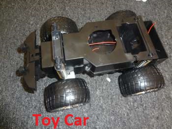
| 2 | Toy car(including two DC Motors) | Grocery Outlet (Any toy store/grocery store such as Walmart) | 1 | $15.00 |
| 3 | Ultrasonic Sensor (HCSr04) | Amazone | 1 | $5:00 |
| 4 | 9V-2000mAh Rechargeable Battery (Nickel-metal Hydride battery) | Frys | 1 | $12:00 |
| 5 | Accessories (Jumper Wires, prototype board and battery charger) | Frys | 1 | $20:00 |
| 6 | Motor Controller (L298 Dual H-Bridge DC Motor Controller) | robotshop | 1 | $18:00 |
| Total Cost | $150:00 |
Design & Implementation
Hardware Design
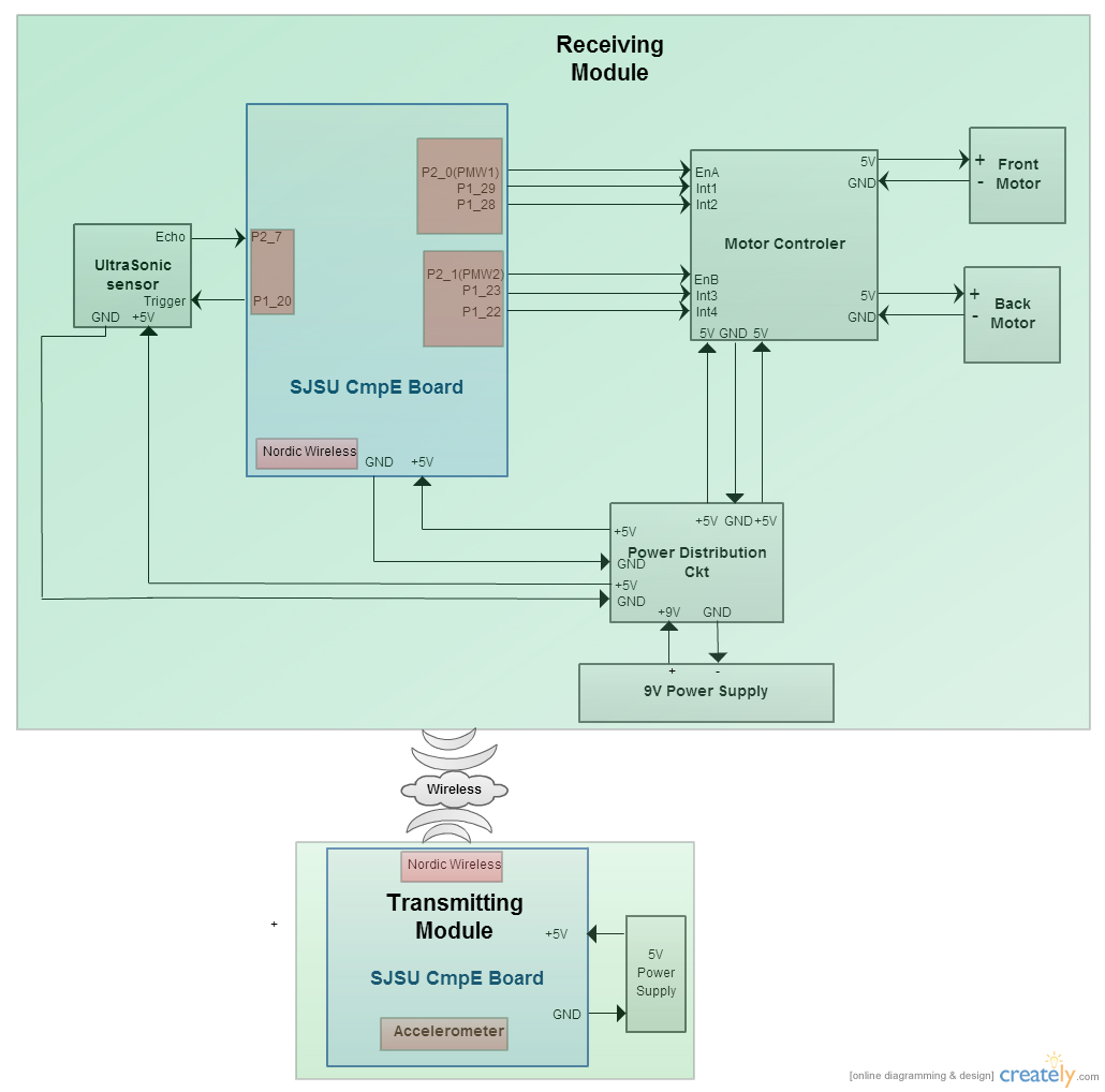
The hardware is designed by going through each project part's datasheet and LPC1758 microcontroller. After understanding the pin connections and the design, all the parts are connected by jumper wires. The Power to the microcontroller is supplied by USB cable which is spliced so that one end is connected to the 5V power supply. The Power source used for this project is rechargeable 9V battery, which is then connected to a power distribution circuit. A Power distribution circuit takes 9V from rechargeable battery converts to 5V.
The Following block diagram shows the overall connection between the project parts:
Hardware Interface
The Transmitting Module used the following interfaces:
- I2C Bus
- Used to read the board orientation from Accelerometer sensor
- SPI Bus
- Used to transmit commands from Nordic wireless from receiving board
- GPIO
- Control Motor direction and speed, read ultrasonic sensor and Switches for start and stop
The Receiving Module board used the following interfaces:
- SPI Bus
- Used for receiving commands from a Nordic wireless from transmitting board
- GPIO
- PWM interface for front and back motor
- Direction control for front and back motor
- Send Trigger to Ultrasonic sensor
- Detect Echo back pulse from Ultrasonic sensor
Software Design
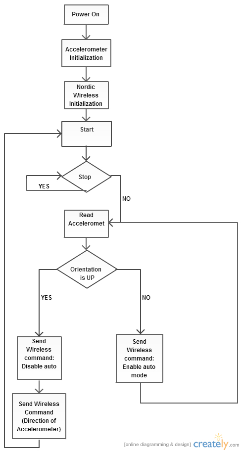
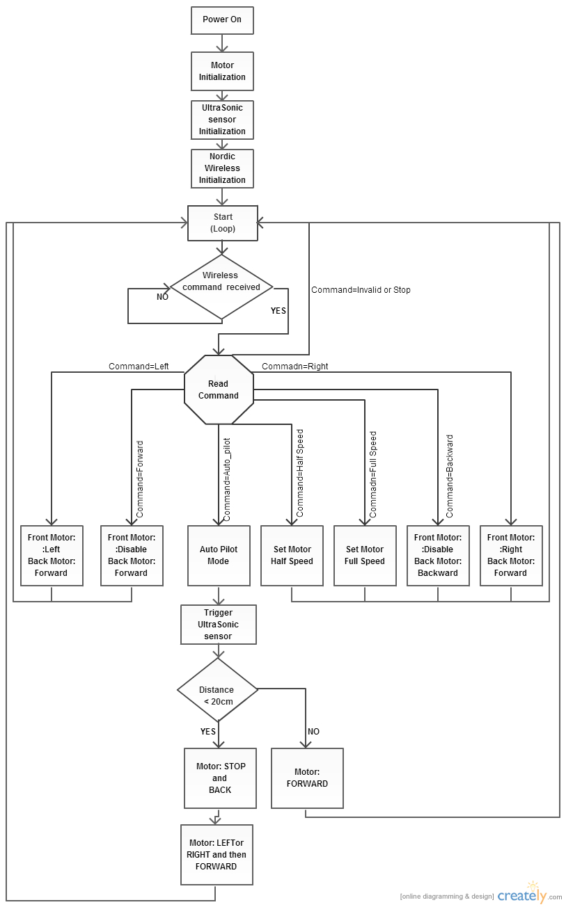
The Software is implemented by following the below flowchart:
Transmitting module
Receiving module
Implementation
Accelerometer sensor (Part: MMA8452Q, inbuilt in SJone board).
The direction of board tilt is calculated by reading the accelerometer sensor. To read the sensor data follow the following steps:
- Step1: Initialize accelerometer sensor
- Set Ctrl1_reg1 register's last bit to 0 to select standby mode.
- Enable Portrait/Landscape status register through PL_Cfg register and set bit 4 in Ctrl_reg4 register.
- set denounce counter to 100ms through PL_count register.
- Set the sensor output data rate (100Mhz) and the ACTIVE mode from Ctrl1_reg1 register.
- Step2: Read Pl_status register from accelerometer sensor to get direction and orientation of the SJone board.
- The following value will determine what direction or orientation the board is:
If bit[1:0] is:
0: Portrait Up
1: Portrait Down
2: Landscape Right
3: Landscape Left
If bit[0] is:
0: Front facing orientation
1: Back facing orientation
Motor Controller (L298 Dual H-Bridge DC Motor Controller). ) The dual Motor controller is used to control the speed and the direction of both front and back motor. Motor controller has one enable and two interrupts pins for each motor. Follow the following steps to control the motors through motor controller:
- Step1: Initialize motor controller
- initialize two PWM signal and then set it to 1KHz frequency in SJone board.
- Configure the speed of the motor through PWM from LPC1758 data sheet.
- I used the inbuilt function provided by the CmpE244 instructor.
      PWM front_Motor.set(int percentage of motor speed)
      The process of converting the percentage of speed is as follow:
      If percent = 70, mTcMax = 1000, then value will be 70*1000 / 100 = 700
      After the calculation, you write these values to the MR memory locations based on which PWM is selected in SJone board.
- Set four GPIO pins for the four interrupt pins as output.
- Step2: Control the direction of motor (clock or anti clock) as following:
                 PWM      Int1        Int2       Function
                 --------------------------------------------------------------
                 High     High        Low        Turn Anti-clockwise (Reverse)
                 High     Low         High       Turn clockwise (Forward)
                 High     High        High         Stop
                 High     Low         Low          Stop
                 Low       X           X           Stop
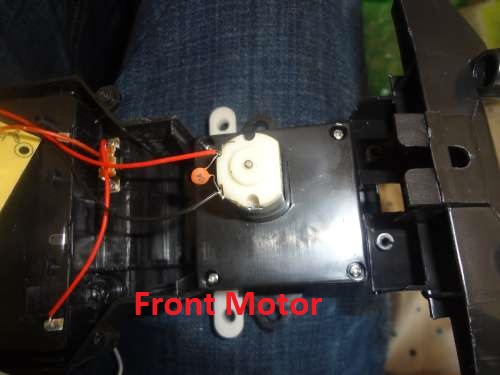
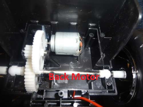
The back motor simply turns the wheels forward and backward. The front motor is attached to a toy car inbuilt mechanical system which turn wheels right when motor runs clockwise and turns left when motor runs anti clock wise.
Nordic Wireless sensor (nRF24L01, inbuilt in SJone board).
Nordic Wireless sensor is used to send and receive the data from one SJboard to other. I used the inbuilt wireless function to send and receive data packets.
   Set the address: mesh_set_node_address(commander_addr)
   Send data: wireless_send(car_addr,mesh_pkt_nack, &command,1,max_hops)
For this project I used following protocol:
  car_addr=300
  commander_addr=400
  Function          Command
  move_forward   :    1
  move_backward  :    2
  move_right     :    3
  move_left      :    4
  stop           :    5
  start          :    10
  full_speed     :    6
  half_speed     :    7
  auto_pilot_on  :    8
  auto_pilot_off :    9
For receiving module, set the address: mesh_set_node_address(car_addr) and then read the data.
Ultrasonic sensor (Pasrt: HCSr04). Ultrasonic sensor is used to detect if any object is in front of the car or not. The ultrasonic sensor has four pins. Two are power and ground pins and other two are Echo and Trigger pins. Trigger pin tells ultrasonic sensor to start sending waves and echo pin assert from low to high if it receive a wave back. By calculating the time between sending and receiving the wave, we can calculate the distance between the reflected object.
The process of initializing ultrasonic sensor is as follows:
- Step1: initialize ultrasonic sensor.
- Set Trigger pin as output
- Set Echo pin as input
- Set interrupt on Echo pin on falling edge (I used in built interrupt enable function for port 2 pins provided by the instructor).
- Step2: Take snapshot of the hardware time. I used timer1 function provided by FreeRTOS.
- Step3: Send High pulse for at least between 15us to 20us on the trigger pin and then send low pulse.
- Step4: Record the hardware time again as soon as a interrupt(falling edge) occur on the echo pin.
- Step5: Calculate the distance as following
- TimeDelta = timerValueAtinterrupt - timerValueAtTrigger
- Convert time from nanosecond to microsecond: TimeDelta = TimeDelta * 0.666. Since at Timer1, Each tick = 1/(48Mhz/32) = 666ns (more info on LPC1758 datasheet)
- TimeDelta = TimeDelta - HoldoffTime (from ultrasonic sensor datasheet)
- Convert calculate time to distance such as into centimetre: distance = TimeDelta /29; (This formula can be found in the ultrasonic sensor datasheet)
**The overall implementation of the whole project is explained in the above flow chart diagram.
Testing & Technical Challenges
Testing of this project is done before and after complete project integration. The whole project is tested by printing the output values from each sensor's to the laptop's terminal screen for validation.
Transmitting module: The software testing of transmitting module is done by printing the value from Accelerometer sensor and the command it sends from Nordic wireless sensor on the terminal screen. The SJone board has inbuilt accelerometer and wireless sensor, so it didn't need any hardware testing.
Receiving module: Receiving module is tested by printing the output value that it received from transmitting module and the value that it sends to the motor controller and the ultrasonic sensor.
Ultrasonic sensor is tested by probing (by oscilloscope) on the trigger and echo pins on the ultrasonic sensor. It validated that the microcontroller is sending the trigger and the sensor is outputting the echo back pulse. The timer1 function provided with the code gives the precise timing result as compared to the inbuilt timing function (such as simple for loop).
Motor controller is tested by printing out the speed and the direction of motor value on the terminal screen. At first the motor didn't run because of low current supply, but after correct power supply it started to run. The interrupt pins needed to be set correctly to rotate the motor clock and anticlockwise.
Complete Project testing: The whole project is tested by connecting everything together and then sending the command through a transmitting board to receiving board and observing its behavior. At first the controlling of car such as direction and speed control was difficult, but after increasing the speed (PWM signal) and fixing the signal send to interrupt pins on the motor controller, the problem was resolved. There was also a delay problem that causes both receiving and transmitting module to control the car more precisely. This is issue was resolved by minimizing the delay that I put in the code after every command that both the boards send and receive.
Conclusion
The whole project experience was fun and very educational. We learned about how sonar sensor, accelerometer sensor, wireless sensor and motor controllers works. We faced some technical challenges such as controlling the motor speed, getting the right distance value from the sonar sensor, and some of the power issues such as the right amount of current to the DC motors.
This project can be expanded to include more features such as an sonar sensor connected to the servo motor that rotates left and right to get distance from all the sides. This can reduce the number of sonar sensors. Furthermore, a improvement can be done in master and motor controller to control the car more precisely by controlling the car movement more accurately. A future suggestion would be to avoid non avoidable obstacles such as grass or follow only the planned route (may be be using some sensors or image detection).
Project Video
Upload a video of your project and post the link here.
Project Source Code
References
Acknowledgement
I would like to thank Professor Preet for encouraging us to learn and build some practical projects related to embedded systems. This was my first embedded project and I learned a lot from it. All the homeworks, the inbuilt programming code and the detailed explanation of the Real-time OS on Embedded System on socialledge website designed by professor Preet helped me to build this project. I thank you once again for this wonderful experience that I gain from taking this course.
References Used
http://www.nxp.com/documents/user_manual/UM10360.pdf
http://www.socialledge.com/sjsu/images/d/de/2012SJOneBoardSchematic.pdf
http://www.freescale.com/files/sensors/doc/data_sheet/MMA8452Q.pdf
http://www.freescale.com/files/sensors/doc/data_sheet/MMA8452Q.pdf
http://www.socialledge.com/sjsu/index.php?title=SJ_One_Board
http://www.socialledge.com/sjsu/index.php?title=Interactive_Wireless_Nodes_Project
http://www.socialledge.com/sjsu/index.php?title=PING)))_Ultrasonic_Sensor
http://www.robotshop.com/en/l298-dual-h-bridge-dc-motor-controller.html
http://content.solarbotics.com/products/datasheets/solarbotics_l298_compact_motor_driver_kit.pdf
http://www.instructables.com/id/Accelerometer-Gyro-Tutorial/
