Difference between revisions of "F24: Bounce Tales"
Proj user8 (talk | contribs) (→Schedule) |
Proj user8 (talk | contribs) (→Bounce Tales) |
||
| (30 intermediate revisions by the same user not shown) | |||
| Line 1: | Line 1: | ||
| − | == | + | = Bounce Tales = |
| − | |||
| − | |||
| − | |||
| − | |||
| − | |||
| − | |||
| − | |||
| − | |||
| − | |||
| − | |||
| − | == | + | <div><ul> |
| − | + | <li style="display: inline-block;">[[File:1.jpeg|thumb|330px|Start Button Press]] </li> | |
| + | <li style="display: inline-block;">[[File:2.jpeg|thumb|330px|Win Screen]] </li> | ||
| + | </ul></div> | ||
== Abstract == | == Abstract == | ||
| Line 18: | Line 10: | ||
== Objectives & Introduction == | == Objectives & Introduction == | ||
| − | + | The idea is to build the bounce tales game on a 64x64 RGB LED Screen. The game is played using a joystick. The ball keeps on collecting the point avoiding the obstacles and its direction can be controlled using left and right control of the joystick, which can also be used in forward direction jump to avoid the obstacles. MP3 decoder is used for different sound effects in the background of game. | |
| + | |||
=== Team Members & Responsibilities === | === Team Members & Responsibilities === | ||
| + | * Shashank | ||
| + | **LED driver | ||
| + | **MP3 decoder driver | ||
| + | **Game Logic | ||
| + | **PCB Schematic and Board Design | ||
| + | **PCB design verification | ||
| + | **WiKi page handling | ||
* Vaidehi | * Vaidehi | ||
| − | ** | + | **LED driver |
| − | * | + | **Game Logic |
| − | ** | + | **PCB design verification |
| + | **WiKi page handling | ||
* Manvendra | * Manvendra | ||
| − | ** | + | **Joystick driver |
| + | **Game Logic | ||
| + | **PCB design verification | ||
| + | **WiKi page handling | ||
== Schedule == | == Schedule == | ||
| Line 103: | Line 107: | ||
* Additional accessories if required and finalization of hardware | * Additional accessories if required and finalization of hardware | ||
| | | | ||
| − | * <span style="color: | + | * <span style="color:green">Completed</span> |
* <span style="color:green">Completed</span> | * <span style="color:green">Completed</span> | ||
* <span style="color:green">Completed</span> | * <span style="color:green">Completed</span> | ||
| Line 147: | Line 151: | ||
* Update the wiki page. | * Update the wiki page. | ||
| | | | ||
| − | * <span style="color: | + | * <span style="color:green">Completed</span> |
* <span style="color:green">Completed</span> | * <span style="color:green">Completed</span> | ||
* <span style="color:green">Completed</span> | * <span style="color:green">Completed</span> | ||
| Line 164: | Line 168: | ||
|- | |- | ||
! scope="row"| 10 | ! scope="row"| 10 | ||
| + | | | ||
| + | *12/9/2024 | ||
| + | *12/9/2024 | ||
| + | *12/18/2024 | ||
| + | *12/19/2024 | ||
| | | | ||
*12/9/2024 | *12/9/2024 | ||
| Line 173: | Line 182: | ||
*Final Demo | *Final Demo | ||
*Update Gitlab repo with final code. | *Update Gitlab repo with final code. | ||
| − | |||
*Update the wiki page. | *Update the wiki page. | ||
| | | | ||
| Line 187: | Line 195: | ||
== Parts List & Cost == | == Parts List & Cost == | ||
| − | + | {| class="wikitable" | |
| + | |- | ||
| + | ! scope="col"| Item# | ||
| + | ! scope="col"| Part Name | ||
| + | ! scope="col"| Part Supplier | ||
| + | ! scope="col"| Quantity | ||
| + | ! scope="col"| Cost | ||
| + | |- | ||
| + | ! scope="row"| 1 | ||
| + | | | ||
| + | 64x64 RGB LED Matrix | ||
| + | | | ||
| + | Amazon | ||
| + | | | ||
| + | 1 | ||
| + | | | ||
| + | $ 87.4 | ||
| + | |- | ||
| + | ! scope="row"| 2 | ||
| + | | | ||
| + | Sjtwo board | ||
| + | | | ||
| + | Amazon | ||
| + | | | ||
| + | 1 | ||
| + | | | ||
| + | $ 50 | ||
| + | |- | ||
| + | ! scope="row"| 3 | ||
| + | | | ||
| + | Two-axis Joystick | ||
| + | | | ||
| + | Amazon | ||
| + | | | ||
| + | 1 | ||
| + | | | ||
| + | $ 4.25 | ||
| + | |- | ||
| + | ! scope="row"| 4 | ||
| + | | | ||
| + | MP3 Decoder | ||
| + | | | ||
| + | Amazon | ||
| + | | | ||
| + | 1 | ||
| + | | | ||
| + | $ 8.05 | ||
| + | |- | ||
| + | ! scope="row"| 5 | ||
| + | | | ||
| + | Power Supply | ||
| + | | | ||
| + | Amazon | ||
| + | | | ||
| + | 1 | ||
| + | | | ||
| + | $ 7.99 | ||
| + | |- | ||
| + | |||
| + | |} | ||
| + | |||
| + | <HR> | ||
| + | <BR/> | ||
== Design & Implementation == | == Design & Implementation == | ||
| − | + | ||
=== Hardware Design === | === Hardware Design === | ||
| − | + | The game has been designed using SJtwo-c board, RGB LED- for visuals, MP3 decoder- for background music, joystick and PCB. The game is controlled by using a two-axis joystick and to play the music we have used an MP3 decoder. | |
| + | ====PIN Configuration==== | ||
| + | {| class="wikitable" style="text-align: center; width: 400px; height: 200px;" | ||
| + | |- | ||
| + | ! PIN number | ||
| + | ! Pin Description | ||
| + | ! SJTwo Board Pin | ||
| + | |- | ||
| + | | || '''LED Matrix''' || | ||
| + | |- | ||
| + | | R1 || Upper half (Section 1) || p2_0 | ||
| + | |- | ||
| + | | G1 || Upper half (Section 1) || p2_1 | ||
| + | |- | ||
| + | | B1 || Upper half (Section 1) || p2_2 | ||
| + | |- | ||
| + | | R2|| Lower half (Section 2) || p2_4 | ||
| + | |- | ||
| + | | G2 || Lower half (Section 2) || p2_5 | ||
| + | |- | ||
| + | | B2 || Lower half (Section 2) || p2_6 | ||
| + | |- | ||
| + | | A || Address Line || p2_7 | ||
| + | |- | ||
| + | | B || Address Line || p2_8 | ||
| + | |- | ||
| + | | C || Address Line || p2_9 | ||
| + | |- | ||
| + | | D || Address Line || p0_16 | ||
| + | |- | ||
| + | | E || Address Line || p0_15 | ||
| + | |- | ||
| + | | GND || Connected to ground || GND | ||
| + | |- | ||
| + | | Clk || For upper half and lower half || p1_28 | ||
| + | |- | ||
| + | | Latch|| For upper half and lower half || p1_23 | ||
| + | |- | ||
| + | | OE || For upper half and lower half || p1_20 | ||
| + | |- | ||
| + | | || '''Joystick''' || | ||
| + | |- | ||
| + | | S-X || X axis data || p0_30 | ||
| + | |- | ||
| + | | S-Y|| Y axis data || p1_25 | ||
| + | |- | ||
| + | | S-K || Switch data || p1_31 | ||
| + | |- | ||
| + | |||
| + | | ||'''MP3 Decoder''' || | ||
| + | |- | ||
| + | | RX || Receiver ||p4_29 | ||
| + | |- | ||
| + | | TX || Transmitter ||p4_28 | ||
| + | |- | ||
| + | | VCC || connected to vcc || 5V | ||
| + | |- | ||
| + | |GND || Connected to ground || GND | ||
| + | |- | ||
| + | |} | ||
| − | === | + | ====Interfacing and Layout==== |
| − | + | {| | |
| + | |[[File:Schematic.PNG|800px|thumb|center|Schematic]] | ||
| + | |} | ||
| − | === | + | === '''LED Matrix''' === |
| − | + | A 64x64 RGB LED Matrix, with a total of 4096 pixels is used for display. Each LED can be fully controlled independently using 13 digital GPIOs. This matrix has six 64-bit shift registers for R1, G1, B1 R2, G2, B2 where each color of the LED is controlled by one bit of the shift register. By combing RGB colors we can make different colors such as YELLOW, CYAN, RED, WHITE, MAGENTA. | |
| + | ==== Technical Specifications==== | ||
| − | === | + | {| class="wikitable" style="text-align: center; width: 400px; height: 200px;" |
| − | + | |- | |
| + | ! Specification | ||
| + | ! Remarks | ||
| + | |- | ||
| + | | Pitch || 3 mm | ||
| + | |- | ||
| + | | Resolution || 64x64 =4096 pixels | ||
| + | |- | ||
| + | | Volt/Amp || 5V/60A | ||
| + | |- | ||
| + | | Scan Rate|| 1/16 | ||
| + | |- | ||
| + | |} | ||
| + | |||
| + | ====LED Matrix Panel==== | ||
| + | {| | ||
| + | |[[File:RGB_Led_matrix.jpg|600px|thumb|right|RGB LED Matrix]] | ||
| + | |||
| + | |} | ||
| − | == | + | === '''Dual Axis Joystick''' === |
| − | + | We have used a 2-axis joystick to control the movements of the jumper. The joystick operates on 5V power and provides analog output, hence it is connected to the ADC pins of the SJtwo-c board. The joystick has two potentiometers, each for X-axis and Y-axis. X-axis values are used to define the left and right directions of the jumper. The switch on the joystick controls the start and stop actions of the game. | |
| − | |||
| − | + | [[File:D_joystick.jpg|500x280px |thumb|center|Dual Axis Joystick]] | |
| − | === | + | === '''MP3 Decoder''' === |
| − | + | The MP3 decoder that we used is serial MP3 player model by Catalex (version v1.0.1). It's a simple MP3 player device which is based on a high-quality MP3 audio chip---YX5300. It can support 8k Hz ~ 48k Hz sampling frequency MP3 and WAV file formats. There is a TF card socket on board, so you can plug the micro SD card that stores audio files. MCU can control the MP3 playback state by sending commands to the module via UART port, such as switch songs, change the volume and play mode and so on. | |
| − | + | [[File:MP3 Decoder.PNG|500x280px |thumb|center|MP3 Decoder]] | |
| − | |||
| − | == | + | == '''IMPLEMENTATION''' == |
| − | + | '''LED Driver''' | |
| − | === | + | A 64*64 led matrix is used for this project. The led matrix is divided into two halves of 32*64 each. It has 3 R,G,B pins and 3 64-bits registers (shift registers) for each upper and lower halves. The address lines provided are 5. This means that at a time same row from the upper half and the lower half will be selected. So in order to display a particular row appropriate row should be selected and appropriate data needs to be fed to the RGB shift registers of both top and bottom halves. |
| − | * | + | LED matrix is initialized by configuring the required pins as output. The led matrix has 3 more pins enable which are essential to display a pixel on the matrix. The clk pin that should used as a clk to the shift registers to shift the data out, the latch pin is used to latch the data from the shift registers onto the matrix's buffer, the output enable pin that is used to display the latched data on the selected row. |
| + | * Before feeding matrix data disable Output Enable (OE) GPIO | ||
| + | * Set bits on A, B, C, D GPIO pins to select the particular row. | ||
| + | * Loop through the pixels (columns) in the selected row and set the pixel color on R, G, B GPIO pins | ||
| + | * To mask that particular pixel set zero on R, G, B GPIO pins | ||
| + | * Set and Reset the clock for pushing the R, G, B bits for each column | ||
| + | * Issue latch to mark the row's completion | ||
| + | * Set OE | ||
| + | * Small delay | ||
| + | * Reset latch before going to next row | ||
| + | |||
| + | |||
| + | '''MP3 Decoder''' | ||
| + | * Integrated different music for every level that keeps on playing in background. | ||
| + | * To get the game state, sound flags are checked. | ||
| + | * Different music for jumps, points collection, game over and collisions. | ||
| + | |||
| + | |||
| + | ''' Code snippet for MP3: ''' | ||
| + | <syntaxhighlight lang="c"> | ||
| + | |||
| + | void mp3__send_command(uint8_t command, uint8_t data_1, uint8_t data_2) { | ||
| + | mp3_uart_buffer[0] = 0x7e; | ||
| + | mp3_uart_buffer[1] = 0xff; | ||
| + | mp3_uart_buffer[2] = 0x06; | ||
| + | mp3_uart_buffer[3] = command; | ||
| + | mp3_uart_buffer[4] = 0x00; | ||
| + | mp3_uart_buffer[5] = data_1; | ||
| + | mp3_uart_buffer[6] = data_2; | ||
| + | mp3_uart_buffer[7] = 0xef; | ||
| + | |||
| + | for (uint8_t i = 0; i < 8; i++) { | ||
| + | uart__polled_put(UART__3, mp3_uart_buffer[i]); | ||
| + | } | ||
| + | } | ||
| + | |||
| + | void mp3__init() { | ||
| + | int mp3_baud_rate = 9600; | ||
| + | uart__init(UART__3, clock__get_peripheral_clock_hz(), mp3_baud_rate); | ||
| + | |||
| + | gpio__construct_with_function(GPIO__PORT_4, 28, GPIO__FUNCTION_2); | ||
| + | gpio__construct_with_function(GPIO__PORT_4, 29, GPIO__FUNCTION_2); | ||
| + | |||
| + | mp3__send_command(SELECT_DEVICE, 0x00, DEV_TF); | ||
| + | mp3_play_start_song(); | ||
| + | } | ||
| + | |||
| + | void mp3_play(int num) { | ||
| + | mp3__send_command(CYCLE_PLAY_FOLDER, num, 0x02); | ||
| + | } | ||
| + | |||
| + | void mp3_play_start_song() { | ||
| + | mp3_play(1); | ||
| + | } | ||
| + | |||
| + | </syntaxhighlight> | ||
| + | |||
| + | '''Joystick''' | ||
| + | |||
| + | * Initialized the ADC Peripheral | ||
| + | * Set the appropriate pin functionality using the IOCON registers. | ||
| + | * Set the ADC pin functionality as input. | ||
| + | * Select ADC channels to read. | ||
| + | * Enable burst mode for a fast conversion. | ||
| + | |||
| + | ''' Code snippet for Joystick: ''' | ||
| + | <syntaxhighlight lang="c"> | ||
| + | |||
| + | |||
| + | void enable_joystick(gpio__port_e adc1, uint8_t x_pin, gpio__port_e adc2, uint8_t y_pin, gpio__port_e port, int pin) { | ||
| + | const uint32_t set_analog_mode = (1 << 7); | ||
| + | |||
| + | LPC_IOCON->P1_30 &= ~(set_analog_mode); | ||
| + | LPC_IOCON->P0_25 &= ~(set_analog_mode); | ||
| + | |||
| + | adc_xvalue = gpio__construct_with_function(adc1, x_pin, 1); | ||
| + | adc_yvalue = gpio__construct_with_function(adc2, y_pin, 3); | ||
| + | adc__initialize(); | ||
| + | } | ||
| + | |||
| + | void initialize_joystick() { | ||
| + | enable_joystick(GPIO__PORT_0, 25, GPIO__PORT_1, 30, GPIO__PORT_1, 31); | ||
| + | button_press = p1; | ||
| + | } | ||
| + | |||
| + | |||
| + | </syntaxhighlight> | ||
| + | |||
| + | |||
| + | |||
| + | |||
| + | === LED Matrix and Game Play === | ||
| + | |||
| + | |||
| + | ===MP3 Decoder === | ||
| + | While integrating the mp3 decoder code with the rest of the code, there occurred an issue in display and game got crashed. | ||
| + | So instead of creating a separate task for mp3 decoder, we just did mp3__init() in main function and the issues got resolved. | ||
| + | |||
| + | =='''CONCLUSION'''== | ||
| + | |||
| + | We successfully met our objectives with "Bounce Tales," capturing the essence of the classic jumping and obstacle games. All game components worked seamlessly during the final demo, ensuring an engaging player experience. The LED matrix effectively displayed obstacles and the player character, and the sound effects for jumping and collisions added to the game's dynamic atmosphere. The demo showcased how players could jump over obstacles to avoid collisions and collect points, with the game ending upon touching any obstacle. This project enhanced our understanding of real-world applications using FreeRTOS, along with integration of drivers, PCB design, power management circuits, git for source code management, and thorough integration testing. It also highlighted the importance of clear requirements, strategic planning, and consistent communication within our team. | ||
== References == | == References == | ||
=== Acknowledgement === | === Acknowledgement === | ||
| − | + | We would like to sincerely thank Professor Preetpal Kang for designing such a knowledgeable course and continuous guidance and support throughout the implementation of this project. Further, we would like to thank the TA for her advice and feedbacks. | |
| − | |||
| − | |||
| − | |||
| − | |||
| − | |||
| − | |||
Latest revision as of 14:39, 20 April 2025
Contents
Bounce Tales
Abstract
Bounce Tales is a classic mobile game reminiscent of the Nokia era, featuring a bouncing character navigating through levels filled with obstacles. This project aims to recreate the game experience using the SJ-2 board and an LED matrix display. Players will control the character’s movement using buttons or a joystick, while the game will include levels, obstacles, and scoring. The implementation will focus on real-time movement, collision detection, and level progression.
Objectives & Introduction
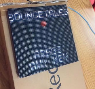
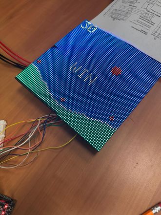
The idea is to build the bounce tales game on a 64x64 RGB LED Screen. The game is played using a joystick. The ball keeps on collecting the point avoiding the obstacles and its direction can be controlled using left and right control of the joystick, which can also be used in forward direction jump to avoid the obstacles. MP3 decoder is used for different sound effects in the background of game.
Team Members & Responsibilities
- Shashank
- LED driver
- MP3 decoder driver
- Game Logic
- PCB Schematic and Board Design
- PCB design verification
- WiKi page handling
- Vaidehi
- LED driver
- Game Logic
- PCB design verification
- WiKi page handling
- Manvendra
- Joystick driver
- Game Logic
- PCB design verification
- WiKi page handling
Schedule
| Week# | Start Date | End Date | Task | Status |
|---|---|---|---|---|
| 1 |
|
|
|
|
| 2 |
|
|
|
|
| 3 |
|
|
|
|
| 4 |
|
|
|
|
| 5 |
|
|
|
|
| 6 |
|
|
|
|
| 7 |
|
|
|
|
| 8 |
|
|
|
|
| 9 |
|
|
|
|
| 10 |
|
|
|
|
Parts List & Cost
| Item# | Part Name | Part Supplier | Quantity | Cost |
|---|---|---|---|---|
| 1 |
64x64 RGB LED Matrix |
Amazon |
1 |
$ 87.4 |
| 2 |
Sjtwo board |
Amazon |
1 |
$ 50 |
| 3 |
Two-axis Joystick |
Amazon |
1 |
$ 4.25 |
| 4 |
MP3 Decoder |
Amazon |
1 |
$ 8.05 |
| 5 |
Power Supply |
Amazon |
1 |
$ 7.99 |
Design & Implementation
Hardware Design
The game has been designed using SJtwo-c board, RGB LED- for visuals, MP3 decoder- for background music, joystick and PCB. The game is controlled by using a two-axis joystick and to play the music we have used an MP3 decoder.
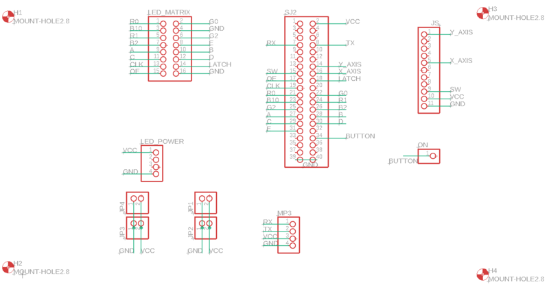
PIN Configuration
| PIN number | Pin Description | SJTwo Board Pin |
|---|---|---|
| LED Matrix | ||
| R1 | Upper half (Section 1) | p2_0 |
| G1 | Upper half (Section 1) | p2_1 |
| B1 | Upper half (Section 1) | p2_2 |
| R2 | Lower half (Section 2) | p2_4 |
| G2 | Lower half (Section 2) | p2_5 |
| B2 | Lower half (Section 2) | p2_6 |
| A | Address Line | p2_7 |
| B | Address Line | p2_8 |
| C | Address Line | p2_9 |
| D | Address Line | p0_16 |
| E | Address Line | p0_15 |
| GND | Connected to ground | GND |
| Clk | For upper half and lower half | p1_28 |
| Latch | For upper half and lower half | p1_23 |
| OE | For upper half and lower half | p1_20 |
| Joystick | ||
| S-X | X axis data | p0_30 |
| S-Y | Y axis data | p1_25 |
| S-K | Switch data | p1_31 |
| MP3 Decoder | ||
| RX | Receiver | p4_29 |
| TX | Transmitter | p4_28 |
| VCC | connected to vcc | 5V |
| GND | Connected to ground | GND |
Interfacing and Layout
LED Matrix
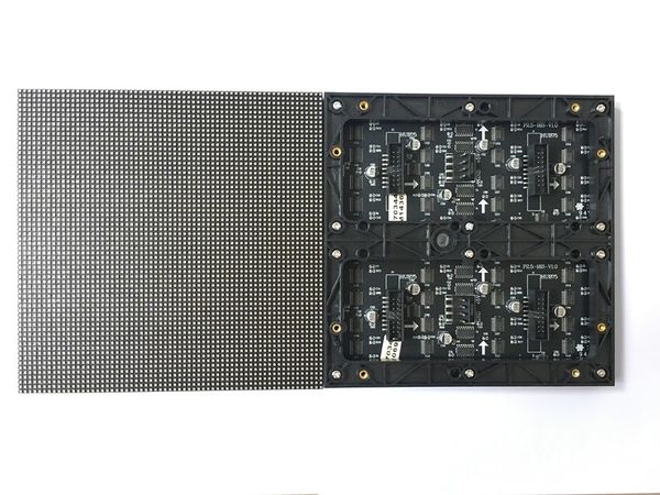
A 64x64 RGB LED Matrix, with a total of 4096 pixels is used for display. Each LED can be fully controlled independently using 13 digital GPIOs. This matrix has six 64-bit shift registers for R1, G1, B1 R2, G2, B2 where each color of the LED is controlled by one bit of the shift register. By combing RGB colors we can make different colors such as YELLOW, CYAN, RED, WHITE, MAGENTA.
Technical Specifications
| Specification | Remarks |
|---|---|
| Pitch | 3 mm |
| Resolution | 64x64 =4096 pixels |
| Volt/Amp | 5V/60A |
| Scan Rate | 1/16 |
LED Matrix Panel
Dual Axis Joystick
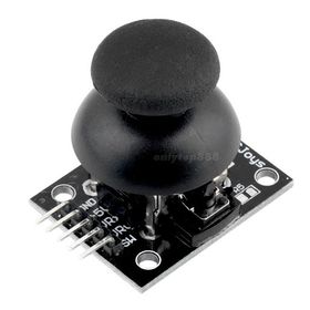
We have used a 2-axis joystick to control the movements of the jumper. The joystick operates on 5V power and provides analog output, hence it is connected to the ADC pins of the SJtwo-c board. The joystick has two potentiometers, each for X-axis and Y-axis. X-axis values are used to define the left and right directions of the jumper. The switch on the joystick controls the start and stop actions of the game.
MP3 Decoder
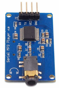
The MP3 decoder that we used is serial MP3 player model by Catalex (version v1.0.1). It's a simple MP3 player device which is based on a high-quality MP3 audio chip---YX5300. It can support 8k Hz ~ 48k Hz sampling frequency MP3 and WAV file formats. There is a TF card socket on board, so you can plug the micro SD card that stores audio files. MCU can control the MP3 playback state by sending commands to the module via UART port, such as switch songs, change the volume and play mode and so on.
IMPLEMENTATION
LED Driver
A 64*64 led matrix is used for this project. The led matrix is divided into two halves of 32*64 each. It has 3 R,G,B pins and 3 64-bits registers (shift registers) for each upper and lower halves. The address lines provided are 5. This means that at a time same row from the upper half and the lower half will be selected. So in order to display a particular row appropriate row should be selected and appropriate data needs to be fed to the RGB shift registers of both top and bottom halves. LED matrix is initialized by configuring the required pins as output. The led matrix has 3 more pins enable which are essential to display a pixel on the matrix. The clk pin that should used as a clk to the shift registers to shift the data out, the latch pin is used to latch the data from the shift registers onto the matrix's buffer, the output enable pin that is used to display the latched data on the selected row.
- Before feeding matrix data disable Output Enable (OE) GPIO
- Set bits on A, B, C, D GPIO pins to select the particular row.
- Loop through the pixels (columns) in the selected row and set the pixel color on R, G, B GPIO pins
- To mask that particular pixel set zero on R, G, B GPIO pins
- Set and Reset the clock for pushing the R, G, B bits for each column
- Issue latch to mark the row's completion
- Set OE
- Small delay
- Reset latch before going to next row
MP3 Decoder
- Integrated different music for every level that keeps on playing in background.
- To get the game state, sound flags are checked.
- Different music for jumps, points collection, game over and collisions.
Code snippet for MP3:
void mp3__send_command(uint8_t command, uint8_t data_1, uint8_t data_2) {
  mp3_uart_buffer[0] = 0x7e;
  mp3_uart_buffer[1] = 0xff;
  mp3_uart_buffer[2] = 0x06;
  mp3_uart_buffer[3] = command;
  mp3_uart_buffer[4] = 0x00;
  mp3_uart_buffer[5] = data_1;
  mp3_uart_buffer[6] = data_2;
  mp3_uart_buffer[7] = 0xef;

  for (uint8_t i = 0; i < 8; i++) {
    uart__polled_put(UART__3, mp3_uart_buffer[i]);
  }
}

void mp3__init() {
  int mp3_baud_rate = 9600;
  uart__init(UART__3, clock__get_peripheral_clock_hz(), mp3_baud_rate);

  gpio__construct_with_function(GPIO__PORT_4, 28, GPIO__FUNCTION_2);
  gpio__construct_with_function(GPIO__PORT_4, 29, GPIO__FUNCTION_2);

  mp3__send_command(SELECT_DEVICE, 0x00, DEV_TF);
  mp3_play_start_song();
}

void mp3_play(int num) {
mp3__send_command(CYCLE_PLAY_FOLDER, num, 0x02);
}

void mp3_play_start_song() {
mp3_play(1);
}
Joystick
- Initialized the ADC Peripheral
- Set the appropriate pin functionality using the IOCON registers.
- Set the ADC pin functionality as input.
- Select ADC channels to read.
- Enable burst mode for a fast conversion.
Code snippet for Joystick:
void enable_joystick(gpio__port_e adc1, uint8_t x_pin, gpio__port_e adc2, uint8_t y_pin, gpio__port_e port, int pin) {
  const uint32_t set_analog_mode = (1 << 7);

  LPC_IOCON->P1_30 &= ~(set_analog_mode);
  LPC_IOCON->P0_25 &= ~(set_analog_mode);

  adc_xvalue = gpio__construct_with_function(adc1, x_pin, 1);
  adc_yvalue = gpio__construct_with_function(adc2, y_pin, 3);
  adc__initialize();
}

void initialize_joystick() {
  enable_joystick(GPIO__PORT_0, 25, GPIO__PORT_1, 30, GPIO__PORT_1, 31);
  button_press = p1;
}
LED Matrix and Game Play
MP3 Decoder
While integrating the mp3 decoder code with the rest of the code, there occurred an issue in display and game got crashed. So instead of creating a separate task for mp3 decoder, we just did mp3__init() in main function and the issues got resolved.
CONCLUSION
We successfully met our objectives with "Bounce Tales," capturing the essence of the classic jumping and obstacle games. All game components worked seamlessly during the final demo, ensuring an engaging player experience. The LED matrix effectively displayed obstacles and the player character, and the sound effects for jumping and collisions added to the game's dynamic atmosphere. The demo showcased how players could jump over obstacles to avoid collisions and collect points, with the game ending upon touching any obstacle. This project enhanced our understanding of real-world applications using FreeRTOS, along with integration of drivers, PCB design, power management circuits, git for source code management, and thorough integration testing. It also highlighted the importance of clear requirements, strategic planning, and consistent communication within our team.
References
Acknowledgement
We would like to sincerely thank Professor Preetpal Kang for designing such a knowledgeable course and continuous guidance and support throughout the implementation of this project. Further, we would like to thank the TA for her advice and feedbacks.
