Difference between revisions of "S23: Meh-sla Automotive"
(→System Hardware Design) |
(→Conclusion) |
||
| (220 intermediate revisions by 2 users not shown) | |||
| Line 1: | Line 1: | ||
| + | {| | ||
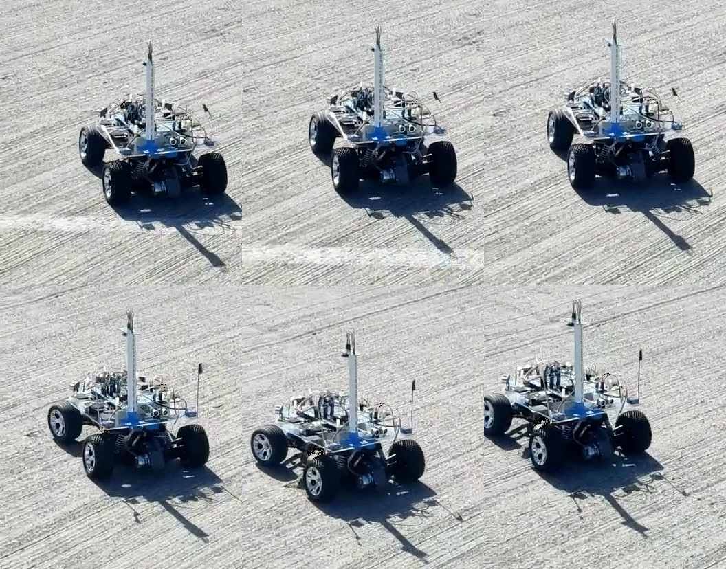
| + | [[File:Meh_sla_flag.jpg|right|350px|thumb|Meh-Sla]][[File:meh_sla.gif|right|500px|thumb|Meh-Sla]] | ||
| + | |} | ||
| + | |||
== Project Title == | == Project Title == | ||
¯\_(ツ)_/¯ Meh-Sla Automotive ¯\_(ツ)_/¯ | ¯\_(ツ)_/¯ Meh-Sla Automotive ¯\_(ツ)_/¯ | ||
| Line 5: | Line 9: | ||
== Abstract == | == Abstract == | ||
| − | The ultimate goal of the project is to design an autonomous car | + | The ultimate goal of the project is to design an autonomous car that navigates from its current location to a destination. Along its way, it needs to avoid obstacles and follow the waypoints. To achieve this we are using four SJ2 boards that communicate with each other via CAN bus along with the required sensors and a mobile app that communicates with one of the SJ2 boards via Bluetooth. |
Through our experience, we knew that we wouldn't be the Worst-Sla. We say that we are Meh-Sla even though we know we are the Best-Sla. | Through our experience, we knew that we wouldn't be the Worst-Sla. We say that we are Meh-Sla even though we know we are the Best-Sla. | ||
| Line 34: | Line 38: | ||
=== Team Members & Responsibilities === | === Team Members & Responsibilities === | ||
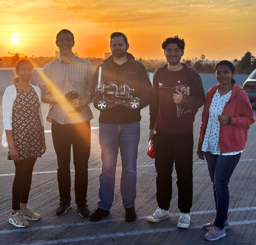
| − | + | [[File: Mehsla Group enhanced_1.png|500px]] | |
[https://gitlab.com/karthigaiamutha.ezhilarasu/meh-sla-automotive Gitlab Project Link] | [https://gitlab.com/karthigaiamutha.ezhilarasu/meh-sla-automotive Gitlab Project Link] | ||
| Line 40: | Line 44: | ||
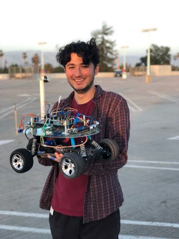
| − | ''''' [https:// | + | [[File:RCAnthonyZunino.jpg|350px]] |
| + | |||
| + | ''''' [https://www.linkedin.com/in/anthonyzunino/ Anthony (Tony) Zunino] ''''' | ||
* Team Lead | * Team Lead | ||
* Motor Board | * Motor Board | ||
| − | ''''' [https:// | + | |
| + | |||
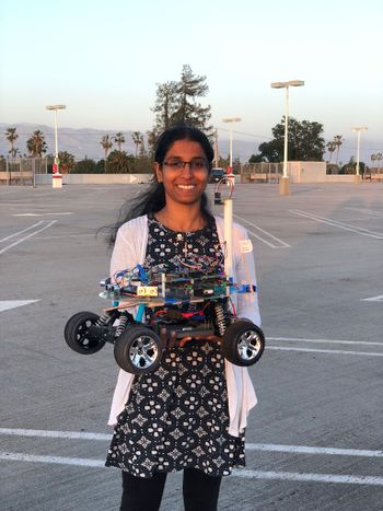
| + | [[File:Mehsla_Sindhuja.jpg|350px]] | ||
| + | |||
| + | ''''' [https://www.linkedin.com/in/sindhuja-ravi/ Sindhuja Ravi] ''''' | ||
* Geo Board | * Geo Board | ||
* Android App | * Android App | ||
| − | ''''' [https:// | + | |
| + | |||
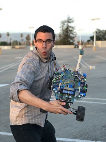
| + | [[File:meh_stephen.jpg|350px]] | ||
| + | |||
| + | ''''' [https://www.linkedin.com/in/stephen-oneto-7836641b9/ Stephen Oneto] ''''' | ||
* Driver and LCD Board | * Driver and LCD Board | ||
| − | ''''' [https:// | + | |
| + | |||
| + | [[File:Mehsla_Amutha.jpg|350px]] | ||
| + | |||
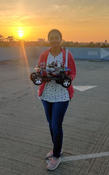
| + | ''''' [https://www.linkedin.com/in/amutha-ezhil/ Karthigai Amutha Ezhilarasu] ''''' | ||
* Sensor Board | * Sensor Board | ||
* Geo Board | * Geo Board | ||
| − | ''''' [https:// | + | |
| − | * Hardware | + | |
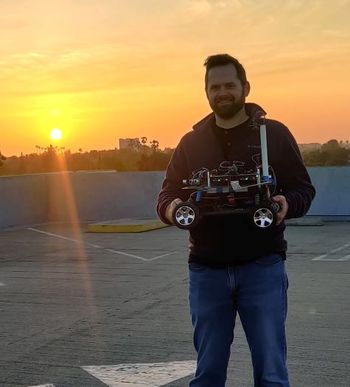
| + | [[File:Mehsla_Phil.jpg|350px]] | ||
| + | |||
| + | ''''' [https://www.linkedin.com/in/phil-bloxom/ Phil Bloxom] ''''' | ||
| + | * Hardware Design | ||
* Software Testing | * Software Testing | ||
| + | |||
| + | |||
<HR> | <HR> | ||
| Line 76: | Line 100: | ||
| 2/18/2023 | | 2/18/2023 | ||
| | | | ||
| − | *<span>Read previous projects, gather information and discuss among group members</span> | + | *<span>Read previous projects, gather information, and discuss among group members</span> |
| | | | ||
*<font color = "green">Completed | *<font color = "green">Completed | ||
| Line 271: | Line 295: | ||
| | | | ||
*<font color = "green">Completed | *<font color = "green">Completed | ||
| − | *<font color = " | + | *<font color = "green">Completed |
*<font color = "green">Completed | *<font color = "green">Completed | ||
|} | |} | ||
| Line 282: | Line 306: | ||
|- | |- | ||
! scope="col"| Item# | ! scope="col"| Item# | ||
| − | ! scope="col"| Part | + | ! scope="col"| Part Description |
! scope="col"| Vendor | ! scope="col"| Vendor | ||
! scope="col"| Qty | ! scope="col"| Qty | ||
| Line 351: | Line 375: | ||
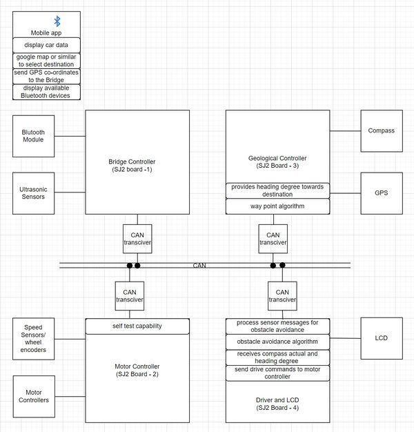
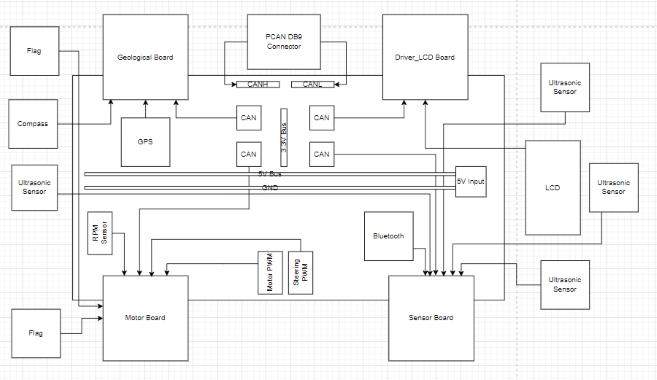
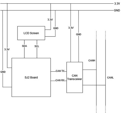
''' Block Diagram ''' | ''' Block Diagram ''' | ||
| − | [[File: | + | [[File:Block_diagram_improved_resolution.jpg|600px]] |
<br> | <br> | ||
| Line 363: | Line 387: | ||
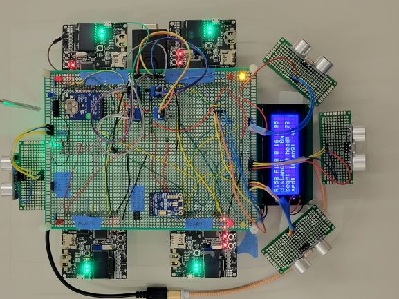
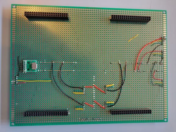
''' Layout Description ''' | ''' Layout Description ''' | ||
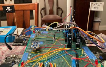
| − | The four SJTwo boards | + | [[File:Mehsla_Top_view.jpg]] |
| + | |||
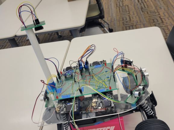
| + | The system implemented four SJTwo boards, positioned with their tops facing upwards and protruding from beneath the PCB. This arrangement allowed for convenient utilization of the onboard LEDs and easy access to the Reset buttons on each board. Although this design choice sacrificed compactness, it provided early access to the LEDs during development. Furthermore, this configuration facilitated the division of the PCB into four quadrants for the rest of the design. | ||
[[File:Mehsla_Power_bus_lines.jpg]] | [[File:Mehsla_Power_bus_lines.jpg]] | ||
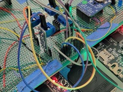
| − | + | To power the entire system, a portable 20,000mAh power bank was employed, connecting to the PCB via a micro USB connector. From the connector, a 5V and GND bus was integrated into the center of the PCB using a bus wire. This power distribution arrangement ensured consistent voltage supply to the four SJTwo boards and other peripherals. By delivering power through a unified 5V line, all voltage references remained relative to each other. Moreover, this design reduced clutter by offering multiple points for connecting 5V and GND, facilitated by the bus running the length of the PCB. | |
| − | [[File:Mehsla_Can_section.jpg]] | + | [[File:Mehsla_Can_section.jpg|400px]] |
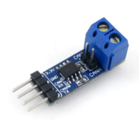
| − | + | To optimize PCB space, the four CAN transceivers were positioned upright in a 2x2 formation between two SJTwo boards. This configuration allowed for the creation of nearby CANH and CANL buses, ensuring easy accessibility for the PCAN dongle. The CAN transceivers were powered by a 3.3V bus created by connecting all the 3.3V SJTwo outputs, thus maintaining consistent voltage levels. | |
| − | + | [[File:Mehsla_LCD_Front_Sensors.jpg]] | |
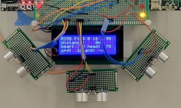
| − | The | + | The four ultrasonic sensors were mounted on daughter boards, offering flexibility for precise directional adjustment without impacting the rest of the system. Three sensors were placed in the front of the car for the right, front, and left directions, while one sensor was positioned at the rear. The LCD screen was strategically placed behind the front sensors to prevent interference and any potential movement in case of dislodgment. |
| − | The GPS and Bluetooth modules were | + | [[File:Mehsla_Compass_pole.jpg]] |
| + | |||
| + | To minimize interference from other components, the compass was mounted on a pole. A lightweight PVC pipe was chosen to allow for wire routing inside it, resulting in a cleaner overall appearance. | ||
| + | |||
| + | The GPS and Bluetooth modules were positioned next to the respective controlling SJTwo board. The motor's battery, ESC, and RPM sensor were all mounted on the vehicle's chassis. | ||
| + | |||
| + | [[File:Mehsla_gps_led.jpg|200px]] | ||
| + | |||
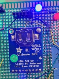
| + | Each board featured a red LED to indicate CAN MIA (Missing in Action). The two front yellow LEDs served as obstacle avoidance indicators: when an object was detected on the right or left side, the corresponding LED would light up, and if an obstacle was detected in the front, both LEDs would illuminate. If neither LED was lit, the car would operate based on path determination rather than obstacle avoidance. The green LED under the PCB indicated power supply, while the blue LED at the back would blink during GPS pairing and remain steadily lit once the GPS successfully locked onto a signal. | ||
| + | |||
| + | |||
| + | === Technical Challenges === | ||
| + | |||
| + | Issue: I didn't have any of the parts when designing the board since they were being utilized by others for their own development purposes. | ||
| + | |||
| + | Solution: I relied heavily on datasheets for spacing of the parts and I checked the datasheet 3-4 times before every wire was soldered. | ||
<HR> | <HR> | ||
| Line 383: | Line 424: | ||
== CAN Communication == | == CAN Communication == | ||
| − | + | We selected our message IDs using a mutually agreed-upon priority scheme. Messages responsible for controlling the car were given high-priority IDs, while sensor and GEO messages were assigned the next level of priority. Debug and status messages received the lowest priority IDs. | |
=== Hardware Design === | === Hardware Design === | ||
| − | + | ||
| + | |||
| + | [[File:Mehsla_Can_Module.png|200px]][[File:Mehsla_CAN_Bus.png|500px]] | ||
| + | |||
| + | |||
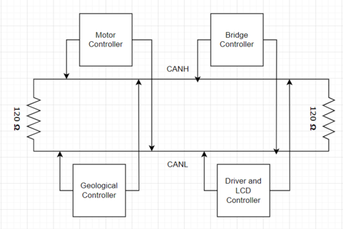
| + | We opted for the Waveshare CAN transceiver in our design due to its exceptional reliability, integrated 120-ohm resistor(we removed them off two boards), vertical mounting capability, and dual CANH/L connectors. The four CAN transceivers were strategically positioned upright in a 2x2 arrangement between two SJTwo boards. This layout facilitated the creation of closely located 5-pin CANH and CANL buses, ensuring effortless access for the PCAN dongle. Powering the CAN transceivers was achieved through a 3.3V bus formed by connecting all the 3.3V SJTwo outputs, guaranteeing consistent voltage levels throughout the system. | ||
=== DBC File === | === DBC File === | ||
| Line 464: | Line 510: | ||
BO_ 300 MOTOR_STATUS: 3 MOTOR | BO_ 300 MOTOR_STATUS: 3 MOTOR | ||
| − | SG_ MOTOR_STATUS_wheel_error : 0|1@1+ (1,0) [0|0] "" DRIVER,IO | + | SG_ MOTOR_STATUS_wheel_error : 0|1@1+ (1,0) [0|0] "" DRIVER,IO,SENSOR |
| − | SG_ MOTOR_STATUS_speed_kph : 8|16@1+ (0.001,0) [0|0] "kph" DRIVER,IO | + | SG_ MOTOR_STATUS_speed_kph : 8|16@1+ (0.001,0) [0|0] "kph" DRIVER,IO,SENSOR |
BO_ 401 MOTOR_DEBUG: 1 MOTOR | BO_ 401 MOTOR_DEBUG: 1 MOTOR | ||
| Line 504: | Line 550: | ||
VAL_ 100 DRIVER_HEARTBEAT_cmd 2 "DRIVER_HEARTBEAT_cmd_REBOOT" 1 "DRIVER_HEARTBEAT_cmd_SYNC" 0 "DRIVER_HEARTBEAT_cmd_NOOP" ; | VAL_ 100 DRIVER_HEARTBEAT_cmd 2 "DRIVER_HEARTBEAT_cmd_REBOOT" 1 "DRIVER_HEARTBEAT_cmd_SYNC" 0 "DRIVER_HEARTBEAT_cmd_NOOP" ; | ||
| + | |||
</pre> | </pre> | ||
| Line 517: | Line 564: | ||
{| | {| | ||
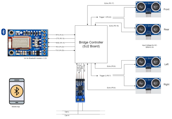
| − | |[[File: | + | |[[File:Bridge_board_block.png|600px|center|thumb|Bridge controller connections]] |
|} | |} | ||
| Line 533: | Line 580: | ||
*Operating Frequency: 40Hz | *Operating Frequency: 40Hz | ||
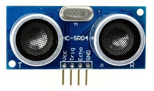
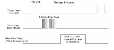
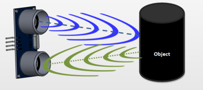
| − | The pinout and the timing diagram of the HC-SR04 sensor are shown in the following figures. The module includes an ultrasonic transmitter, a receiver, and a control circuit. The basic principle of work: When the trigger pin is set HIGH for at least 10us, the module automatically sends a 40 kHz ultrasonic wave from the Ultrasonic transmitter. This wave travels in the air and when it gets obstructed by any material it gets reflected | + | The pinout and the timing diagram of the HC-SR04 sensor are shown in the following figures. The module includes an ultrasonic transmitter, a receiver, and a control circuit. The basic principle of work: When the trigger pin is set HIGH for at least 10us, the module automatically sends a 40 kHz ultrasonic wave from the Ultrasonic transmitter. This wave travels in the air and when it gets obstructed by any material it gets reflected toward the sensor. This reflected wave is observed by the Ultrasonic receiver module. Once the wave is returned the Echo pin goes high for a particular amount of time which will be equal to the time taken for the wave to return to the sensor. The amount of time during which the Echo pin stays high is measured by the SJ2 board as it gives the information about the time taken for the wave to return to the Sensor. Using this information the distance is measured as explained in the above heading. From that duration, the distance at which the object is present can be measured using the formula, Distance = Speed × Time. |
| − | {| | + | |
| − | |[[File: | + | {| |
| − | [[File:Sensor_working.png|400px| | + | |[[File:Ulrasonic_sensor.jpg|300px|center|thumb|HC-SR04 Timing Diagram]] ||[[File:Sensor_timing_diagram.jpg|400px|center|thumb|HC-SR04 Timing Diagram]] || [[File:Sensor_working.png|400px|center|thumb|HC-SR04 Working Principle]] |
| − | |||
|} | |} | ||
| Line 589: | Line 635: | ||
==== Bluetooth Module ==== | ==== Bluetooth Module ==== | ||
| − | Bluetooth module is used to send the debug information such as sensor values, current heading, bearing, distance to the destination, and current GPS location to the mobile app. Also, it receives the destination coordinates and start/stop | + | Bluetooth module is used to send the debug information such as sensor values, current heading, bearing, distance to the destination, and current GPS location to the mobile app. Also, it receives the destination coordinates and start/stop signals from the mobile app. To differentiate between the coordinates and the start/stop signal we used the first char as '@' or '#'. If the starting char is '@', the message contains the destination coordinate. Similarly, "#0' represents the stop signal, and '#1' represents the start signal. |
| − | |||
''''' Bluetooth initialization ''''' | ''''' Bluetooth initialization ''''' | ||
| Line 628: | Line 673: | ||
==== Sensor module ==== | ==== Sensor module ==== | ||
| − | *''' Issue:''' Sometimes the front sensor was detecting some obstacles even though there was nothing in front. | + | *''' Issue:''' Sometimes the front sensor was detecting some obstacles even though there was nothing in front. This may be due to the reception of the reflected signal from the right or left sensor. |
*''' Solution:''' We included a delay of 10ms in between triggering the first and second pair of sensors. | *''' Solution:''' We included a delay of 10ms in between triggering the first and second pair of sensors. | ||
| Line 644: | Line 689: | ||
== Motor Controller == | == Motor Controller == | ||
| + | |||
| + | * [https://gitlab.com/karthigaiamutha.ezhilarasu/meh-sla-automotive/-/tree/motor_board?ref_type=heads Motor Controller Gitlab link] | ||
| + | |||
| + | === Hardware Design === | ||
| + | |||
| + | ===== Block Diagram ===== | ||
| + | |||
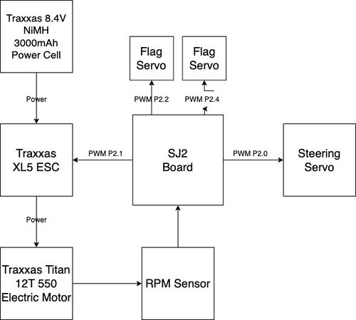
| + | Below is the high-level block diagram of the Meh-Sla Motor Controller system. Originally, the Traxxas RC car came with a TQ Top Qualifier 2.4GHz radio system which gave the PWM signals to the motor controller and steering servo. We hijacked those signals and connected them to the SJ2 board's P2.1 and P2.0, both PWM pins, for the motor and steering, respectively. There are two other PWM pins used to control two flags: a pirate flag and a Meh-Sla flag. Without these flags, our drive to move forward in this project would have halted *wink wink*. Lastly, a RPM sensor (a Hall effect sensor) provides a trigger using a small magnet to P2.6 on the SJ2 board, which will affect the PWM speed sent to the ESC. | ||
| + | |||
| + | [[File:MotorControllerBlockDiagram.jpg|500px|center|Motor Controller Block Diagram]] | ||
| + | |||
| + | ===== Initial Configuration ===== | ||
| + | |||
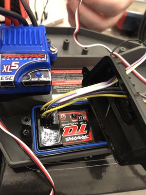
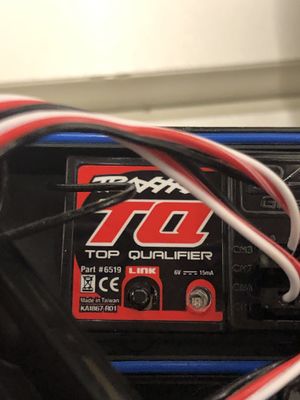
| + | Initially, the PWM came from this TQ Top Qualifier 2.4GHz radio receiver, which received input from a Traxxas TQ Transmitter (AKA a remote control). When I first took apart the receiver, I had to disconnect the ESC and Steering Servo PWM control, but wanted to leave access to the receiver. I put in temporary female wires to let me switch from SJ2 controlling the system to the transmitter. | ||
{| | {| | ||
| − | |[[File:traxxasRemotePWM.jpeg|300px|center | + | |[[File:traxxasRemotePWM.jpeg|300px|center|Traxxas Antenna PWM Connections]] || [[File:TraxxasAntennaDevice.jpg|300px|center|Traxxas TQ Top Qualifier Module]] |
| | | | ||
|} | |} | ||
| − | + | ===== Battery Management ===== | |
| − | + | The Traxxas RC car came with an 8.4V 3000mAh NiMH power cell, which is used to power the Titan electric motor. Originally, this battery was going to be used to power the rest of the peripherals of the Meh-Sla car (Geo/Sensors/Driver/Motor SJ2 boards), but, after testing the battery life, it was quickly found that there was not enough power and an alternative was needed. | |
| − | + | Now the system is equipped with a dual-battery configuration, comprising one battery exclusively for the motor and another dedicated to powering the SJTwo boards and peripherals. This deliberate arrangement ensured an uninterrupted power supply to the controller boards, enabling them to function optimally under all circumstances. The secondary power source for the controller boards consists of a portable 20,000 mAh battery, delivering a reliable 5V output to energize the entire system. | |
| − | |||
| − | + | The Traxxas 3000-series Power Cell NiMH battery provided the power for both the brushless motor and the ESC. It was an 8.4V 3000mAh NiMH battery, which came included with the car. There was no need to replace it as it served its purpose effectively. | |
| − | |||
=== Software Design === | === Software Design === | ||
| − | + | Below are the different modules defined in the motor_board branch ([https://gitlab.com/karthigaiamutha.ezhilarasu/meh-sla-automotive/-/tree/motor_board?ref_type=heads motor_board Gitlab link]). There is a module for each of the two PWM pins, P2.1 and P2.0, controlling the motor and steering, respectively. There is a module implementing the RPM hall effect sensor, and a module, argh, which controls the pirate and Meh-Sla flag. | |
| − | ===== | + | ===== Motor Module (motor.c) ===== |
| − | + | The motor module is simplistic and uses a signal, dbc_MOTOR_SPEED_s, from the Driver board to set the target speed in kph. Before determining what the PWM should be set to, a check for what the current speed is made by using a function from the rpm module, rpm__get_speed(). Then, a simple yet effective proportional algorithm is used to calculate the new target speed in kph. If the phone application has the car turned ON, then a speed_in_percent is set in a global static variable to be used in motor__run_periodic_10Hz(). Additionally, a check is made if the car is going in reverse, as there is a reverse sequence needed to move backward. A state machine could enhance this whole module, but the simplicity worked for our application. | |
| − | void | + | These static helpers calculate the proportional target speed and return a PWM double to control the motor speed. The motor__calculate_motor_pwm() function does not have a check for corner cases as the ESC is not fairly sensitive, and the bounds of what is returned never exceed 10.0 to 20.0 (the range of the ESC's PWM control). |
| − | + | ||
| + | static double motor__calculate_proportional_speed(double target_speed) { | ||
| + | return (target_speed + (target_speed - rpm__get_speed())); | ||
| + | } | ||
| + | |||
| + | static double motor__calculate_motor_pwm(double speed_in_percent) { | ||
| + | return neutral_speed_pwm + (max_speed_offset_pwm * speed_in_percent * max_speed_in_percent / 10000); | ||
| + | } | ||
| + | |||
| + | Below is the main function that determined the percent speed to send given a target kph. The method returns a bool for if it is successful or not. This gives the can_handler information on whether the car is turned on or not to light up an LED. | ||
| + | |||
| + | bool motor__motor_speed_pwm(dbc_MOTOR_SPEED_s *motor_speed_s) { | ||
| + | double speed_in_percent = 0.0; | ||
| + | bool motor_speed_success = false; | ||
| + | double target_motor_speed = motor__calculate_proportional_speed(motor_speed_s->DC_MOTOR_DRIVE_SPEED_sig); | ||
| + | is_reverse = false; | ||
| + | if (car_on_off) { | ||
| + | if (target_motor_speed > 15) | ||
| + | speed_in_percent = 95.0; | ||
| + | if ((target_motor_speed > 10) & (target_motor_speed <= 15)) | ||
| + | speed_in_percent = 70.0; | ||
| + | if ((target_motor_speed > 6) & (target_motor_speed <= 10)) | ||
| + | speed_in_percent = 50.0; | ||
| + | if ((target_motor_speed > 2) & (target_motor_speed <= 6)) | ||
| + | speed_in_percent = 30.0; | ||
| + | if ((target_motor_speed > -2) & (target_motor_speed <= 2)) | ||
| + | speed_in_percent = -30.0; // brake instead of neutral speed | ||
| + | if (target_motor_speed <= -2) | ||
| + | speed_in_percent = -90.0; | ||
| + | motor_speed_pwm = motor__calculate_motor_pwm(speed_in_percent); | ||
| + | motor_speed_success = true; | ||
| + | } else { | ||
| + | motor_speed_pwm = neutral_speed_pwm; | ||
| + | } | ||
| + | return motor_speed_success; | ||
| + | } | ||
| + | |||
| + | ===== Steering Module (steering.c) ===== | ||
| + | The Steering module is very similar to the motor module, but simplified as there is no proportional control to account for. The Steering module takes in a signal, dbc_MOTOR_ANGLE_s and dbc_BRIDGE_APP_COMMANDS_s to control the angle from -45 to 45deg and turn the car on or off, respectively. If the phone application has the car turned ON, then a percent_angle is set in a global static variable to be used in steering__run_periodic_10Hz(). | ||
| + | |||
| + | Below is the main function to determine angle of the steering. The method returns a bool for if it is successful or not. This gives the can_handler information on whether the car is turned on or not to light up an LED. | ||
| + | |||
| + | bool steering__servo_angle_pwm(dbc_MOTOR_ANGLE_s *motor_angle_s) { | ||
| + | double percent_angle = 0.0; | ||
| + | bool steering_angle_success = false; | ||
| + | double const current_decoded_motor_angle = motor_angle_s->SERVO_STEER_ANGLE_sig; // -45 to 45deg | ||
| + | if (car_on_off) { | ||
| + | if (current_decoded_motor_angle > 30) { | ||
| + | percent_angle = -100.0; // turn right | ||
| + | } else if ((current_decoded_motor_angle > 15) & (current_decoded_motor_angle <= 30)) { | ||
| + | percent_angle = -50.0; | ||
| + | } else if ((current_decoded_motor_angle > -15) & (current_decoded_motor_angle <= 15)) { | ||
| + | percent_angle = 0.0; | ||
| + | } else if ((current_decoded_motor_angle > -30) & (current_decoded_motor_angle <= -15)) { | ||
| + | percent_angle = 50.0; | ||
| + | } else if (current_decoded_motor_angle <= -30) { | ||
| + | percent_angle = 100.0; // turn left | ||
| + | } | ||
| + | steering_angle_pwm = steeering__calculate_steering_pwm(percent_angle); | ||
| + | steering_angle_success = true; | ||
| + | } else { | ||
| + | steering_angle_pwm = neutral_steer_angle_pwm; | ||
| + | } | ||
| + | return steering_angle_success; | ||
| + | } | ||
| + | |||
| + | ===== RPM Module (rpm.c) ===== | ||
| + | The RPM module is difficult and complex at its core despite the simplicity of the application. The rpm__init() is a bit longer than other inits as a look into the lower level driver modules is needed to: turn on one of the LPC408X peripheral timers, in this case TIMER2, enable a timer counter with a prescalar divider of the clock__get_peripheral_clock_hz(), generate an interrupt on each event (every rotation of the Hall effect sensor), enable interrupts to call an ISR which resets the timer counter back to zero and reset the interrupt, and finally initialize pin P2.6 to the TIMER2 Capture. | ||
| + | |||
| + | void rpm__init(void) { | ||
| + | // TODO make const uints | ||
| + | uint32_t const prescalar_divider = 959; // 96MHz clk / 960 divider == 100kHz == 10us | ||
| + | kph_scalar *= clock__get_peripheral_clock_hz() / (prescalar_divider + 1); | ||
| + | lpc_peripheral__turn_on_power_to(LPC_PERIPHERAL__TIMER2); | ||
| + | LPC_TIM2->IR |= 0x3F; | ||
| + | LPC_TIM2->CCR = (1 << 0) | (1 << 2); // load capture register 0 (CR0) with TC, and generate interrupt on CAPn.0 event | ||
| + | lpc_peripheral__enable_interrupt(LPC_PERIPHERAL__TIMER2, timer2_isr, NULL); | ||
| + | LPC_TIM2->PR = prescalar_divider; | ||
| + | LPC_TIM2->TCR |= (1 << 0); // enable timer counter + prescalar | ||
| + | gpio__construct_with_function(GPIO__PORT_2, 6, GPIO__FUNCTION_3); | ||
} | } | ||
| − | + | Finally, the capture register 0 which stores the time for one rotation, multiplied by kph_scalar (circumference and gear ratio calculation) to determine speed. | |
| − | |||
| − | + | void rpm__update_speed_10Hz(void) { | |
| − | + | uint32_t timer_capture_value = LPC_TIM2->CR0; | |
| + | if (timer_capture_value == 0) { | ||
| + | timer_capture_value = 1; | ||
| + | } | ||
| + | double const offset = 25000; // used to be 44500 | ||
| + | |||
| + | speed_in_kph = (kph_scalar - offset) / timer_capture_value; | ||
| + | if ((speed_in_kph < 0.5) || (speed_in_kph > 100)) { | ||
| + | speed_in_kph = 0.111; | ||
| + | } | ||
} | } | ||
| − | ===== | + | ===== Argh Module (argh.c) ===== |
| − | + | The Argh module is simple, and pulls a signal from dbc_GEO_STATUS_s to determine the GEO_STATUS_DISTANCE_TO_DESTINATION. Based on how far away the RC car is from its location, the PWM signal to raise the flag will increase (raise) as the distance decreases. An additional argh__dance_seqeunce() was created for when the location has been reached, but not used as it utilizes delay()'s which span longer than the 10Hz periodic call (resetting the board). A future design can implement a binary semaphor outside of the periodic which sleeps until destination reaches zero, then calls this function from it's own dedicated module file. Pins P2.2 and P2.4 are used for each flag. Argh! | |
| + | |||
| + | void argh__servo_angle_pwm(dbc_GEO_STATUS_s *geo_status_s) { | ||
| + | double percent_argh = 0.0; | ||
| + | current_decoded_distance = geo_status_s->GEO_STATUS_DISTANCE_TO_DESTINATION; // -999m to 0m | ||
| − | + | if (current_decoded_distance > 60) { | |
| − | + | percent_argh = -75.0; // flag down | |
| − | + | } else if ((current_decoded_distance > 40) & (current_decoded_distance <= 60)) { | |
| − | + | percent_argh = -25.0; | |
| + | } else if ((current_decoded_distance > 20) & (current_decoded_distance <= 40)) { | ||
| + | percent_argh = 0.0; | ||
| + | } else if ((current_decoded_distance > 10) & (current_decoded_distance <= 20)) { | ||
| + | percent_argh = 50.0; | ||
| + | } else if (current_decoded_distance <= 10) { | ||
| + | percent_argh = 175.0; // flag up | ||
| + | } | ||
| + | argh_pwm = argh__calculate_argh_pwm(percent_argh); | ||
} | } | ||
| + | void argh__run_periodic_10Hz(void) { | ||
| + | pwm1__set_duty_cycle(PWM1__2_2, argh_pwm); | ||
| + | pwm1__set_duty_cycle(PWM1__2_4, | ||
| + | argh__calc_opposite_pwm(argh_pwm)); // servo is flipped so need PWM in the other direction | ||
| + | // if (current_decoded_distance < 2) { // Give semaphor to trigger dance task in main waiting for semaphor | ||
| + | // argh__dance_seqeunce(); | ||
| + | // } | ||
| + | } | ||
=== Technical Challenges === | === Technical Challenges === | ||
| − | + | *''' Issue:''' Reverse was not working when sending a PWM signal between 10.0 and 15.0. | |
| + | *''' Solution:''' Need to send a signal between 10.0-15.0 to BRAKE first, then signal back to neutral 15.0, then can reverse 10.0-15.0 | ||
| − | + | *''' Issue:''' Proportional speed was not working as expected. | |
| − | + | *''' Solution:''' Proportional can only work as well as it can without also implementing I and D. In our case, a fully-charged battery was a work-around. | |
== Geological Controller == | == Geological Controller == | ||
| Line 699: | Line 864: | ||
=== Hardware Design === | === Hardware Design === | ||
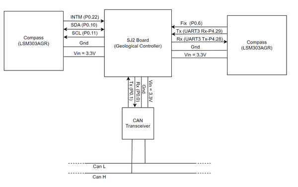
| − | + | {| | |
| + | |[[File:Geoboard_block1.png|600px|center|thumb|Geological controller connections]] | ||
| + | |} | ||
==== Compass ==== | ==== Compass ==== | ||
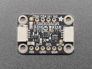
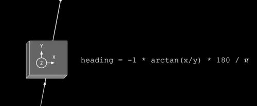
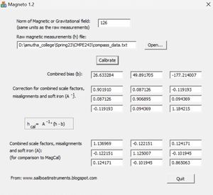
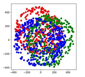
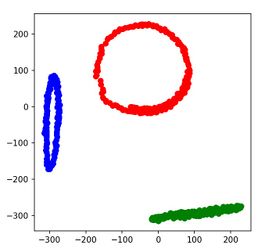
| − | The compass we used is from Adafruit, [https://www.adafruit.com/product/4413?gclid=CjwKCAjwpayjBhAnEiwA-7enayVZ1oqspn3Z_ZNsNPUi7wO4tqkm28mrj1AW6-68-PmlMGMcyf00gBoC_CMQAvD_BwE LSM303AGR breakout]. It has both a magnetometer and an accelerometer. But, We didn't use the accelerometer which is also needed to properly calibrate the compass because the compass couldn't be aligned exactly parallel to the ground when mounting on a car(instead we used a simple trick - see technical challenges for a detailed description). The compass communicates with the SJ2 board via I2C. It operates on 3.3V. It is a triple-axis accelerometer/magnetometer compass module. The magnetometer is mounted on the car with the Z axis pointing away from the ground and X and Y axis pointing as shown in the image below (we can also switch the x and y, but the formula remains the same). The x and y values shown in the formula correspond to the raw x and y values | + | The compass we used is from Adafruit, [https://www.adafruit.com/product/4413?gclid=CjwKCAjwpayjBhAnEiwA-7enayVZ1oqspn3Z_ZNsNPUi7wO4tqkm28mrj1AW6-68-PmlMGMcyf00gBoC_CMQAvD_BwE LSM303AGR breakout]. It has both a magnetometer and an accelerometer. But, We didn't use the accelerometer which is also needed to properly calibrate the compass because the compass couldn't be aligned exactly parallel to the ground when mounting on a car(instead we used a simple trick - see technical challenges for a detailed description). The compass communicates with the SJ2 board via I2C. It operates on 3.3V. It is a triple-axis accelerometer/magnetometer compass module. The magnetometer is mounted on the car with the Z axis pointing away from the ground and X and Y axis pointing as shown in the image below (we can also switch the x and y, but the formula remains the same). The x and y values shown in the formula correspond to the magnetometer's raw x and y values. The compass should be placed as much as away from all the electronics in the car. We used a PVC pipe to place the compass in an elevated position. Even after the elevated positioning, we faced interference that makes it necessary to calibrate the compass. For the compass calibration, we used a third-party calibration tool. [https://sites.google.com/view/sailboatinstruments1 Magneto]. |
{| | {| | ||
|[[File:Magnetometer.jpg|300px|center|thumb|LSM303AGR]] || | |[[File:Magnetometer.jpg|300px|center|thumb|LSM303AGR]] || | ||
| Line 719: | Line 886: | ||
==== GPS ==== | ==== GPS ==== | ||
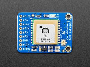
| − | The GPS module we used is [https://www.adafruit.com/product/746?gclid=CjwKCAjwpayjBhAnEiwA-7ena258wLD55o05YFhGdJvbVAbcfqocBw6_NO-c0Ovl14zDI_V7lc5mZxoCcZAQAvD_BwE MTK3339-based breakout] from Adafruit. It is interfaced with the SJ2 board through UART. It will output NMEA strings at a default baud rate of 9600. We parsed the latitude and longitude from the GPGGA data and used them to compute the bearing and distance to the destination. | + | The GPS module we used is [https://www.adafruit.com/product/746?gclid=CjwKCAjwpayjBhAnEiwA-7ena258wLD55o05YFhGdJvbVAbcfqocBw6_NO-c0Ovl14zDI_V7lc5mZxoCcZAQAvD_BwE MTK3339-based breakout] from Adafruit. It is interfaced with the SJ2 board through UART. It will output NMEA strings at a default baud rate of 9600. We parsed the latitude and longitude from the GPGGA data and used them to compute the bearing and distance to the destination. In addition to the onboard LED on the GPS breakout board, we also included an external LED for the FIX indication of the GPS module. The onboard FIX LED will blink every second until it gets a FIX. Once it gets a FIX, it will blink once every 15sec. But our external LED will use the inverted logic(Turn OFF once every 15 sec).In addition to that to minimize the time required to get the FIX we also included a coin battery to the GPS module. |
{| | {| | ||
| Line 727: | Line 894: | ||
=== Software Design === | === Software Design === | ||
| + | The Geological Board receives the coordinates of the final destination to be reached, from the CAN bus which is sent from the sensor board. It also gets the current location from the GPS module. Based on these two pieces of information, it computes the bearing angle and distance to the destination using the haversine formula. We can also simply use the Pythagorean theorem since the effect of the curvature of the earth is negligible when the distance is very small. The compass shows the current heading of the vehicle. Once we implemented the basic GPS navigation the waypoints are included. Based on the waypoint algorithm, the appropriate waypoint is selected and the bearing for that point is computed based on the current location of the car. Once the car reaches that waypoint, the next waypoint will be selected and the bearing will be again calculated. The computed waypoints are then transmitted over the CAN bus where the driver board receives them and determine which direction the vehicle needs to steer. Once the distance to the destination is less than 5 meters the bearing and the distance to the destination variables will be set to zero. This indicates to the driver board that the destination is reached and it will send the corresponding command to the motor board. | ||
| + | |||
| + | ''''' Compass Calibration ''''' | ||
| + | <pre> | ||
| + | static void compass__calibrate_data(void) { | ||
| + | const float x_bias = -29.407230; | ||
| + | const float y_bias = 108.110692; | ||
| + | const float z_bias = -97.675555; | ||
| + | // misalignmnet_and_soft_iron_correction_factor | ||
| + | const float A[3][3] = { | ||
| + | {1.249033, 0.029467, -0.017773}, {0.029467, 1.362204, -0.047282}, {-0.017773, -0.047282, 1.333366}}; | ||
| + | |||
| + | compass_raw_data.x = A[0][0] * (compass_raw_data.x - x_bias) + A[0][1] * (compass_raw_data.y - y_bias) + | ||
| + | A[0][2] * (compass_raw_data.z - z_bias); | ||
| + | compass_raw_data.y = A[1][0] * (compass_raw_data.x - x_bias) + A[1][1] * (compass_raw_data.y - y_bias) + | ||
| + | A[1][2] * (compass_raw_data.z - z_bias); | ||
| + | compass_raw_data.z = A[2][0] * (compass_raw_data.x - x_bias) + A[2][1] * (compass_raw_data.y - y_bias) + | ||
| + | A[2][2] * (compass_raw_data.z - z_bias); | ||
| + | } | ||
| + | </pre> | ||
| + | |||
| + | ''''' GPS data handling ''''' | ||
| + | <pre> | ||
| + | static void gps__transfer_data_from_uart_driver_to_line_buffer(void) { | ||
| + | char byte; | ||
| + | const uint32_t zero_timeout = 0; | ||
| + | if (uart__is_initialized(gps_uart)) { | ||
| + | while (uart__get(gps_uart, &byte, zero_timeout)) { | ||
| + | line_buffer__add_byte(&line, byte); | ||
| + | } | ||
| + | } else { | ||
| + | printf("Uart3 is not initialized\n"); | ||
| + | } | ||
| + | } | ||
| + | </pre> | ||
| + | |||
| + | ''''' Geo status dbc signal generation ''''' | ||
| + | <pre> | ||
| + | dbc_GEO_STATUS_s geo_node__determine_heading_bearing_and_distance(void) { | ||
| + | dbc_GEO_STATUS_s current_geo_status = {0}; | ||
| + | current_geo_status.GEO_STATUS_COMPASS_HEADING = compass__get_current_heading(); | ||
| + | if (!geo_node__arrived_at_destination()) { | ||
| + | current_geo_status.GEO_STATUS_COMPASS_BEARING = geo_node__compute_current_bearing(); | ||
| + | current_geo_status.GEO_STATUS_DISTANCE_TO_DESTINATION = geo_node__compute_distance_to_destination(); | ||
| + | } | ||
| + | return current_geo_status; | ||
| + | } | ||
| + | </pre> | ||
==== Waypoint Algorithm ==== | ==== Waypoint Algorithm ==== | ||
| + | |||
| + | The primary purpose of the Waypoint Algorithm is to guide an autonomous car along a predefined route, optimizing its trajectory and ensuring the vehicle adheres to the desired path. The algorithm allows the car to navigate through complex environments by strategically selecting waypoints based on real-time data, such as sensor readings, traffic conditions, and map information. The main objectives of implementing this algorithm in our project include achieving precise localization, efficient path planning, obstacle avoidance, and successful completion of the intended journey. | ||
| + | |||
| + | |||
{| | {| | ||
|[[File:Waypoint_mehsla.png|600px|center|thumb|Waypoints we chose]] | |[[File:Waypoint_mehsla.png|600px|center|thumb|Waypoints we chose]] | ||
|} | |} | ||
| + | |||
| + | |||
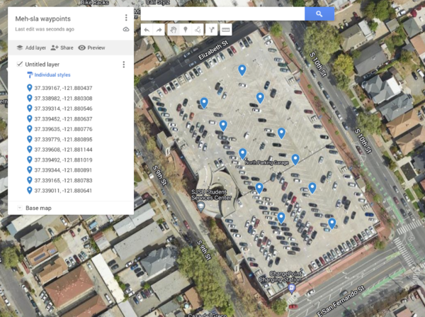
| + | Our waypoint algorithm utilizes a series of predetermined coordinates known as waypoints to guide the autonomous car from its origin to the final destination. Rather than simply moving in a single direction, the algorithm follows a path that connects these waypoints. The waypoints act as checkpoints along the route, ensuring that the car stays on track. In our project, we have selected 11 waypoints arranged, as shown in the above image. | ||
| + | |||
| + | When the car receives the final coordinates of the destination, the waypoint algorithm is executed on the Geo Controller Node. Its primary objective is to identify the best waypoint for the car to follow. To determine the best waypoint, the algorithm considers two conditions. First, it selects the closest waypoint to the car's current location. Second, it ensures that the distance from this chosen waypoint to the destination is less than the distance between the car's current coordinates and the final coordinates. | ||
| + | |||
| + | Once the algorithm identifies the optimal waypoint, it calculates the bearing, which represents the direction in which the car needs to move in order to reach that waypoint. This bearing information is then relayed to the Driver Node, which provides instructions to the car, guiding it towards the designated waypoint. | ||
| + | |||
| + | In summary, our waypoint algorithm uses predetermined coordinates as checkpoints along the route. It selects the best waypoint based on proximity and ensures that the waypoint brings the car closer to the final destination. By calculating the bearing, the algorithm provides directional instructions to the car, enabling it to navigate towards the specified waypoint effectively. | ||
=== Technical Challenges === | === Technical Challenges === | ||
| − | + | *''' Issue:''' The compass behaves perfectly when we test it separately. But once we mount it on the car we receive bizarre values. This is because we didn't calibrate the compass to nullify the hard and soft iron distortion which arises from other components mounted on the car. | |
| + | *''' Solution:''' We did the calibration using a third-party tool. | ||
| − | + | *''' Issue:''' After calibration, we noticed that there is an offset of 70 degrees between the original north and the north pointed by our compass. This may be because the compass was not perfectly aligned parallel to the earth's surface. | |
| − | + | *''' Solution:''' To solve this issue, we should also include the accelerometer reading from the compass. But instead, we simply added an offset manually in the code. This is because the offset is linear. | |
| + | |||
| + | *''' Issue:''' After fixing the above two problems, we noticed that the compass values are flipped (for example, it shows 5 degrees when the actual degree is 355 degrees). | ||
| + | *''' Solution:''' We made a mistake in the conversion of raw value to degree conversion(flipped x and y). Once we fix this, the values seem fine. | ||
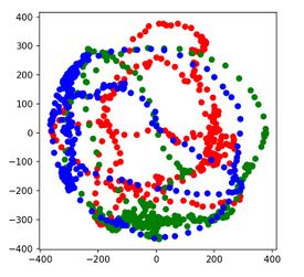
| + | *''' Issue:''' During our initial GPS testing, we noticed that the GPS returns strings that contain only commas and no valid data. This is because the GPS was still getting to try valid data from at least 3 satellites(not yet get a FIX). This was quite confusing at first since we are not aware that the GPS module has less chance of getting a FIX when working indoors. | ||
| + | *''' Solution:''' Do the GPS testing outdoors. If you are doing it indoors, use an external antenna and attach it near the window where there is visibility for a clear sky. | ||
<HR> | <HR> | ||
<BR/> | <BR/> | ||
| Line 746: | Line 980: | ||
* [https://gitlab.com/karthigaiamutha.ezhilarasu/meh-sla-automotive/-/tree/driver_board Driver and LCD Controller Gitlab link] | * [https://gitlab.com/karthigaiamutha.ezhilarasu/meh-sla-automotive/-/tree/driver_board Driver and LCD Controller Gitlab link] | ||
| − | + | === Hardware Design === | |
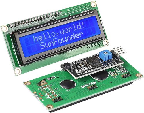
| − | + | The hardware integration on this board is plain and simple. Like the other boards, the driver board is connected to the CAN bus for communication with the CAN network. In this case, CAN2 is used. The LCD screen used is a SunFounder TWI 1602 Serial LCD Module and is interfaced over an I2C bus through the I2C2 port. All components are tied to a common ground and ran off of the board's 3.3V rail. | |
| − | + | [[File:i2c_lcd_screen.jpg|500px]] [[File:meh_driver_hardware.jpg|500px]] | |
=== Software Design === | === Software Design === | ||
| − | + | The driver board is in charge of generating commands to be sent to the motor board over the CAN bus as well as interfacing to the LCD screen to display useful debug data. The software integration consists of a couple of periodic callback functions. | |
| + | |||
| + | ==== Receive Handling/Data Processing ==== | ||
| + | The primary software task of the driver board is to process incoming sensor data and output commands to be sent to the motor board. This is facilitated in a periodic task running a few key handlers at 10Hz. The high-level task is shown below: | ||
| + | |||
| + | void periodic_callbacks__10Hz(uint32_t callback_count) { | ||
| + | gpio__toggle(board_io__get_led1()); | ||
| + | can_bus_handler__process_all_received_messages(); | ||
| + | can_bus_handler__transmit_messages(); | ||
| + | driver_mia__manage_mia(10); | ||
| + | } | ||
| + | |||
| + | Using a generic CAN bus handler that leverages the APIs given in can_bus.h, the task first dequeues all received CAN messages and stores them in the private data structures of their corresponding modules. Next, the data is processed, motor commands are generated, and the appropriate messages are sent over the CAN bus. Once all messages are sent, an MIA monitor is run to ensure that messages are being received as expected. | ||
| + | |||
| + | ===== Motor Commands Generation Handler ===== | ||
| + | The generation of the appropriate motor commands follows simple high-level logic: if it is determined that there is an obstacle nearby, the motor commands sent are to circumnavigate the obstacle. If not, the motor commands would reflect the path toward the destination. Then, the commands are sent over the CAN bus. | ||
| + | |||
| + | void motor_commands_handler__generate_motor_commands(void) { | ||
| + | /** | ||
| + | * obstacle_avoidance__run_algorithm() detects if there is an obstacle nearby, | ||
| + | * and if there is, it will generate the necessary motor commands. If not, the | ||
| + | * motor commands will be generated by the geo data to motor command translation | ||
| + | * function geo_data__handler_translate_to_motor_commands() | ||
| + | */ | ||
| + | if (!obstacle_avoidance__run_algorithm()) { | ||
| + | path_determination__translate_to_motor_commands(); | ||
| + | } | ||
| + | motor_commands__encode_and_send_over_can_bus(); | ||
| + | } | ||
| + | |||
| + | |||
| + | ====== Obstacle Avoidance ====== | ||
| + | Using data received over the CAN bus from the sensor board, the obstacle avoidance algorithm determines whether or not an object is within close proximity to the car, and generates the appropriate motor commands. The pseudocode is as follows: | ||
| + | |||
| + | bool obstacle_avoidance_algorithm() { | ||
| + | get_sonar_data_from_sonar_handler_module(); | ||
| + | if (any_sensor_reading_below_threshold()) { | ||
| + | obstacle_is_near = true; | ||
| + | if (left_is_closer()) { | ||
| + | steer_based_on_how_close_car_is_to_object(steer_right); | ||
| + | } else if (right_is_closer()) { | ||
| + | steer_based_on_how_close_car_is_to_object(steer_left); | ||
| + | } else if (front_is_closer()) { | ||
| + | // Arbitrarily choose to steer left if both right and | ||
| + | // left are equidistant to an object | ||
| + | steer_based_on_how_close_car_is_to_object(steer_left); | ||
| + | } | ||
| + | } else { | ||
| + | obstacle_is_near = false; | ||
| + | go_straight(); | ||
| + | } | ||
| + | calculate_speed_based_on_how_close_front_sensor_is(); | ||
| + | populate_motor_command_structures(); | ||
| + | return obstacle_is_near; | ||
| + | } | ||
| + | |||
| + | ====== Path Determination ====== | ||
| + | If the obstacle avoidance algorithm determines that there are no obstacles nearby, the path determination algorithm runs. The path determination algorithm leverages the data sent from the geological controller. This data includes the current heading of the car, the bearing of the destination based on the current coordinates, and the distance to the destination. Using some simple modular arithmetic, the steering angle can be determined by subtracting heading from bearing. A special case that needs consideration is when the absolute value of the result is greater than 180. This would result in the car taking a longer steering path than needed. To account for this, 360 is either added or subtracted depending on whether the result is positive or negative. | ||
| + | |||
| + | void path_determination__translate_to_motor_commands(void) { | ||
| + | dbc_GEO_STATUS_s geo_data = geo_data_handler__get_latest_geo_data(); | ||
| + | dbc_MOTOR_ANGLE_s *angle_struct = motor_commands__get_steering_angle_struct_ptr(); | ||
| + | uint16_t bearing = geo_data.GEO_STATUS_COMPASS_BEARING; | ||
| + | uint16_t heading = geo_data.GEO_STATUS_COMPASS_HEADING; | ||
| + | int16_t difference = bearing - heading; | ||
| + | if (abs(difference) > 180) { | ||
| + | (difference < 0) ? (difference += 360) : (difference -= 360); | ||
| + | } | ||
| + | if (abs((int)difference) > 45) { | ||
| + | if (difference < 0) { | ||
| + | angle_struct->SERVO_STEER_ANGLE_sig = -45; | ||
| + | } else { | ||
| + | angle_struct->SERVO_STEER_ANGLE_sig = 45; | ||
| + | } | ||
| + | } else { | ||
| + | angle_struct->SERVO_STEER_ANGLE_sig = difference; | ||
| + | } | ||
| + | } | ||
| + | |||
| + | ==== LCD Screen ==== | ||
| + | The LCD screen software implementation is split into a two key modules: a low-level API for controlling the screen itself and an app-specific handler for displaying all of the necessary debug information on the screen | ||
| + | |||
| + | ===== Low-level API ===== | ||
| + | At the lowest level, the screen control API utilizes the I2C API provided in the drivers folder of the SJ2 project. The function to write raw data over the I2C bus is as follows: | ||
| + | |||
| + | void expanderWrite(uint8_t _data) { | ||
| + | uint8_t data_transfer = ((_data) | _backlightval); | ||
| + | i2c__write_single(I2C__2, _Addr, 0x00, data_transfer); | ||
| + | } | ||
| + | |||
| + | The upper layers of the API are largely based on an Arduino library for the particular LCD screen that we are using. These layers essentially format basic strings/characters into the appropriate data/commands to be sent to the LCD, giving the user of the API a nice level of abstraction. The upper layers also provide APIs for initializing the display, adjusting settings, and performing actions such as clearing the screen. | ||
| + | |||
| + | ===== App-Specific Handler ===== | ||
| + | The app-specific LCD screen handler leverages this low-level API to write information about the current state of the car to the screen. Due to its lower priority, this is done in a 1Hz periodic task. | ||
| + | |||
| + | The data that the screen prints out is as follows: | ||
| + | * Sonar sensor distance readings (front, back, left, right) | ||
| + | * Heading and Bearing | ||
| + | * Distance to Destination | ||
| + | * Current speed and steering angle being sent to motor board | ||
| + | |||
| + | The LCD handler gets all of this information by utilizing the APIs corresponding to each data field and converting the values and formatting them into strings using the sprintf() function. | ||
| + | |||
| + | static void get_system_stats(void) { | ||
| + | sonar_sensor_data = sonar_data_handler__get_last_sonar_msg(); | ||
| + | geo_status_data = geo_data_handler__get_latest_geo_data(); | ||
| + | motor_angle_data = *motor_commands__get_steering_angle_struct_ptr(); | ||
| + | motor_speed_data = *motor_commands__get_motor_speed_struct_ptr(); | ||
| + | } | ||
| + | |||
| + | void lcd_handler__print_system_stats(void) { | ||
| + | get_system_stats(); | ||
| + | format_and_print_stat_strings(); | ||
| + | } | ||
=== Technical Challenges === | === Technical Challenges === | ||
| + | '''Problem:''' The car would steer erratically even though there were no objects present. | ||
| + | |||
| + | '''Solution:''' This was the result of erroneous/inaccurate readings coming from the ultrasonic sensors. Due to their cheap nature, the problem was not easily avoidable from the hardware side other than mounting the sensors slightly more consistently with one another. To mitigate this issue, a filtering algorithm was implemented on the sensor board. This algorithm averages out the last N sensor readings and sends the resulting value to the motor board. This way, any outlying spikes in sensor readings would not have as drastic of an effect as the non-filtered data. In addition, a longer between the sensors' sampling times was added to avoid sonic interference. The thresholds for obstacle detection were tweaked to be a little lower. | ||
| + | |||
| + | |||
| + | '''Problem:''' The car would drive in a "snake-like" pattern in narrower hallways and corridors | ||
| − | + | '''Solution:''' This was the result of a few issues. For one, the thresholds of obstacle detection were not well-balanced. The snaking pattern was the result of the thresholds being too low, allowing the car to get much closer to an obstacle before deciding to turn. As a result, the car would turn much more intensely and would over-steer. On the flip side, having the thresholds too high would result in the car always abiding to the obstacle avoidance algorithm rather than allowing the path determination algorithm to take over. In addition, the steering algorithm was originally rather primitive, only allowing the steering angle to be from a set of fixed values based on the range in which the sensor reading were in. For example, if an object was between 2 - 3 feet away, the steering angle would be ±15 degrees depending if it was on the left or right, it was between 1 - 2 feet, the steering angle the steering angle would be ±25 degrees, and so on. To smooth things out, the steering algorithm was changed to scale the steering algorithm based on the exact distance to an obstacle. Rather than having particular steps, the angle became fully dynamic. This helped a lot with the snaking issue as the car would steer less intensely as it moved away from the obstacle and would straighten out faster. | |
| + | |||
| + | |||
| + | '''Problem:''' The car would slow to a halt too soon. | ||
| + | |||
| + | '''Solution:''' The solution to this was similar to the snaking issue, except the scaling algorithm was applied to the speed. This helped a lot not only with slowing down properly, but maintaining a safe speeds from the get go. | ||
<HR> | <HR> | ||
<BR/> | <BR/> | ||
| + | == Mobile Application == | ||
| + | * [https://gitlab.com/Sindhuja_Ravi/sjtwo-c/-/tree/Mehsla_connect_app Mobile app Gitlab link] | ||
| − | + | {| | |
| − | + | |[[File:Mehsla_app_image1.jpg|250px]] || | |
| + | |[[File:Mehsla_app_image2.jpg|250px]] || | ||
| + | |[[File:Mehsla_app_image3.jpg|250px]] || | ||
| + | |[[File:Mehsla_app_image4.jpg|250px]] || | ||
| + | |} | ||
=== Hardware Design === | === Hardware Design === | ||
| + | |||
| + | * Android supportive app was developed and was used to run the application. | ||
| + | * Adafruit Bluefruit LE(Bluetooth module) was used to establish communication between the application and the Bridge Controller. | ||
=== Software Design === | === Software Design === | ||
| − | + | ||
| + | * Software used for Mobile App development - Android Studio Flamingo version. | ||
| + | * Coding language- Java | ||
| + | |||
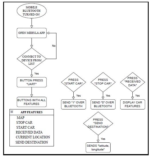
| + | ==== Software Design Flowchart ==== | ||
| + | |||
| + | * Mehsla Connect software design flow is shown below: | ||
| + | |||
| + | [[File:Mehsla_App_flowchart.jpg|550px]] | ||
| + | |||
| + | |||
| + | ==== '''Meh-sla connect App Features''' ==== | ||
| + | |||
| + | * Once we open the Meh-sla connect app, we can see the list of available bluetooth devices. | ||
| + | * Connect to the Adafruit Bluefruit LE module and once connected we can see the features of the app. | ||
| + | * "CURRENT LOCATION" button - Locates our current location. Just long press anywhere on the map to set as destination. | ||
| + | * "SEND DESTINATION" - Sends the destination latitude and longitude to the Bluetooth module. | ||
| + | * "START CAR" - Sends '1' to the bluetooth module from where the bridge sends it to the motor to start the car. | ||
| + | * "STOP CAR" - Sends '0' to the bluetooth module from where the bridge sends it to the motor to stop the car. | ||
| + | * "RECEIVED DATA" - Displays the debug information of the car. | ||
| + | * "MAP" - Takes back from the display data UI to the map UI to pick location. | ||
| + | |||
=== Technical Challenges === | === Technical Challenges === | ||
| − | + | *''' Issue:''' Connecting the Bluetooth module and the App. Initially for a week, though the adafruit bluetooth module was getting listed in available devices, we weren't able to connect to the module. | |
| + | |||
| + | *''' Solution:''' Note down the MAC address, and UUID of the Bluetooth module you use. | ||
| + | |||
| + | |||
| + | *''' Issue:''' If you don't have prior experience in Mobile App development like setting up an account in the Google Cloud console, enabling the API, and using the API key in the Android studio App Manifest file. | ||
| + | |||
| + | *''' Solution:''' Read through the Developer's website. Also, make sure you enable all the privacy settings for accessing the Google Maps SDK. | ||
| + | |||
| + | *''' Issue:''' While displaying the data in the mobile app, we found that the data was not consistent enough as we failed to check the debug information data before we send it. | ||
| + | |||
| + | *''' Solution:''' Use CAN Bus Master to check if you receive the required debug data as expected and then ensure you send the data as a complete frame. Also, make sure to include an algorithm to receive and split the data before displaying it. | ||
<BR/> | <BR/> | ||
| Line 780: | Line 1,179: | ||
<HR> | <HR> | ||
<BR/> | <BR/> | ||
| + | |||
== Conclusion == | == Conclusion == | ||
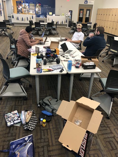
| − | + | The Meh-Sla RC car came together because of the hard-work and determination of the entire team. Any more or fewer people would have taken away from the perfect team dynamic that led to each prototype miraculously working each following demo day. Everyone took charge of their system and made an active effort to work outside of class (and each weekend meet-up) to ensure their modules/functions/git contributions were working and communicated any issues on WhatsApp. It is difficult to manage the schedules of everyone's lives, especially considering out-of-school responsibilities, but the professor, Preet, provided a background and environment for students to transition away from just working on this project to ''enjoying'' this project. | |
| + | |||
| + | If you are a future CMPE243 student, or anyone interested in starting this project from scratch, take pictures and never forget each moment of the process. Your teammates will become your friends through the debugging and issues that arise in the project. You will find joy (and maybe a few tears) in sharing the difficulties of the project with one another, but that should never take away from the passion that will grow from working on this project. | ||
| + | |||
| + | We are all proud of the system we made. We are all happy with the work we have done. We are ecstatic that it is all over! But, we will never forget this project and the fun that we shared! | ||
| − | + | [[File:MeetingOne.jpg|500px]] | |
| + | |||
| + | === What We Learned === | ||
| + | * The CAN bus is an excellent protocol for effectively organizing message transmission and reception within a system. | ||
| + | * A complex project like an autonomous car can be broken down into smaller much simpler parts | ||
| + | * The simplest solution can often be the most effective for solving a problem. | ||
| + | * Only one person should work on a branch at a time. | ||
| + | * The more you plan at the beginning, the smoother things go because everyone has an understanding of who is doing what. | ||
| + | ** This also allowed for each other to identify if someone was falling behind and needed help. | ||
=== Project Video === | === Project Video === | ||
| + | [https://youtu.be/QRx4_HuSzo4 Demo Video Link] | ||
=== Project Source Code === | === Project Source Code === | ||
| + | [https://gitlab.com/karthigaiamutha.ezhilarasu/meh-sla-automotive Gitlab Project Link] | ||
| − | === | + | === Advice for Future Students === |
| − | + | * Plan out the project before you start working on it | |
| + | ** Make SW and HW Block Diagrams | ||
| + | * Review the wiki pages for all of the previous groups | ||
| + | ** Focus on Advice and Challenges Sections | ||
| + | * Don't write bugs in your code | ||
| + | ** The time spent fixing bugs could be used for implementing extra features | ||
| + | * Plan to meet in a group for 4-5 hours every weekend for system integration | ||
| + | ** This should NOT be the only time spent on the project! Everyone should be working throughout the week individually. | ||
| + | * Don't over-engineer your code | ||
| + | * DON'T FORGET GROUND FOR PWM/PCAN/POWER!!! | ||
| + | * Be the Best-sla that you can be! | ||
=== Acknowledgement === | === Acknowledgement === | ||
| + | |||
| + | Without Preet, this project would not have existed. | ||
=== References === | === References === | ||
| + | |||
| + | *[https://web.eece.maine.edu/~zhu/book/lab/HC-SR04%20User%20Manual.pdf HC-SR04 datasheet ] | ||
| + | *[https://www.movable-type.co.uk/scripts/latlong.html Bearing and Distance computation formulas ] | ||
| + | *[https://learn.adafruit.com/introducing-the-adafruit-bluefruit-le-uart-friend Bluetooth Tutorial] | ||
| + | *[https://www.mouser.com/datasheet/2/389/lsm303agr-954987.pdf Compass datasheet] | ||
| + | *[https://learn.adafruit.com/adafruit-ultimate-gps/overview GPS tutorial] | ||
| + | *[https://www.youtube.com/watch?v=cGI8mrIanpk&ab_channel=DigiKey Compass calibration tutorial] | ||
| + | *[https://sites.google.com/view/sailboatinstruments1 Compass calibration tool] | ||
Latest revision as of 04:18, 27 May 2023
Contents
Project Title
¯\_(ツ)_/¯ Meh-Sla Automotive ¯\_(ツ)_/¯
Abstract
The ultimate goal of the project is to design an autonomous car that navigates from its current location to a destination. Along its way, it needs to avoid obstacles and follow the waypoints. To achieve this we are using four SJ2 boards that communicate with each other via CAN bus along with the required sensors and a mobile app that communicates with one of the SJ2 boards via Bluetooth. Through our experience, we knew that we wouldn't be the Worst-Sla. We say that we are Meh-Sla even though we know we are the Best-Sla.
Introduction
The project was divided into 5 modules:
1) Sensor and bridge controller:
- Interfaced with 4 ultrasonic sensors for obstacle detection.
- Interfaced with a Bluetooth module for the controller to mobile app communication.
2) Motor controller:
- Interfaced with vehicle motor to control its speed and steering.
- Interfaced with RPM sensors to get feedback about the vehicle's speed.
3) Geographical controller:
- Interfaced with a magnetometer to get the current heading of the vehicle.
- Interfaced with a GPS module to get the current location information.
4) Driver and LCD controller:
- Process information from the sensor and geological board, and send speed and steering to the motor board based on obstacle avoidance and path determination algorithm.
- Interfaced with an LCD module to display the vehicle status.
5) Mobile App:
- Communicates over Bluetooth.
- Sends destination location or start/stop signal to the car.
- Receives sensor and other navigation status and displays it.
Team Members & Responsibilities
- Team Lead
- Motor Board
- Geo Board
- Android App
- Driver and LCD Board
- Sensor Board
- Geo Board
- Hardware Design
- Software Testing
Schedule
| Week # | Start Date | End Date | Task | Status |
|---|---|---|---|---|
| 1 | 2/12/2023 | 2/18/2023 |
|
|
| 2 | 2/19/2023 | 2/25/2023 |
|
|
| 3 | 26/2/2023 | 3/4/2023 |
|
|
| 4 | 3/5/2023 | 3/11/2023 |
|
|
| 5 | 3/12/2023 | 3/18/2023 |
|
|
| 6 | 3/19/2023 | 3/25/2023 |
|
|
| 7 | 3/26/2023 | 4/1/2023 |
|
|
| 8 | 4/2/2023 | 4/8/2023 |
|
|
| 9 | 4/9/2023 | 4/15/2023 |
|
|
| 10 | 4/16/2023 | 4/22/2023 |
|
|
| 11 | 4/23/2023 | 4/29/2023 |
|
|
| 12 | 4/30/2023 | 5/6/2023 |
|
|
| 13 | 5/7/2023 | 5/13/2023 |
|
|
| 14 | 5/14/2023 | 5/19/2023 |
|
|
| 15 | 5/20/2023 | 5/26/2023 |
|
|
Parts List & Cost
| Item# | Part Description | Vendor | Qty | Cost |
|---|---|---|---|---|
| 1 | RC Car | Traxxas | 1 | $250.00 |
| 2 | SJ2 board | From Preet [1] | 4 | $50.00 |
| 3 | CAN Transceivers (SN65HVD230) | Waveshare [2] | 4 | Free Samples |
| 4 | RC Car RPM | Traxxas [3] | 1 | $8.23 |
| 5 | Adafruit Bluetooth BLE Friend | Adafruit [4] | 1 | $17.5 |
| 6 | GPS Module | Adafruit [5] | 1 | $29.95 |
| 7 | Compass Module | Adafruit [6] | 1 | $12.50 |
| 8 | Ultrasonic Sensors | Adafruit [7] | 4 | $3.95 |
| 9 | LCD Screen | Amazon [8] | 1 | $12.89 |
System Hardware Design
Block Diagram
Layout Diagram
Layout Description
The system implemented four SJTwo boards, positioned with their tops facing upwards and protruding from beneath the PCB. This arrangement allowed for convenient utilization of the onboard LEDs and easy access to the Reset buttons on each board. Although this design choice sacrificed compactness, it provided early access to the LEDs during development. Furthermore, this configuration facilitated the division of the PCB into four quadrants for the rest of the design.
To power the entire system, a portable 20,000mAh power bank was employed, connecting to the PCB via a micro USB connector. From the connector, a 5V and GND bus was integrated into the center of the PCB using a bus wire. This power distribution arrangement ensured consistent voltage supply to the four SJTwo boards and other peripherals. By delivering power through a unified 5V line, all voltage references remained relative to each other. Moreover, this design reduced clutter by offering multiple points for connecting 5V and GND, facilitated by the bus running the length of the PCB.
To optimize PCB space, the four CAN transceivers were positioned upright in a 2x2 formation between two SJTwo boards. This configuration allowed for the creation of nearby CANH and CANL buses, ensuring easy accessibility for the PCAN dongle. The CAN transceivers were powered by a 3.3V bus created by connecting all the 3.3V SJTwo outputs, thus maintaining consistent voltage levels.
The four ultrasonic sensors were mounted on daughter boards, offering flexibility for precise directional adjustment without impacting the rest of the system. Three sensors were placed in the front of the car for the right, front, and left directions, while one sensor was positioned at the rear. The LCD screen was strategically placed behind the front sensors to prevent interference and any potential movement in case of dislodgment.
To minimize interference from other components, the compass was mounted on a pole. A lightweight PVC pipe was chosen to allow for wire routing inside it, resulting in a cleaner overall appearance.
The GPS and Bluetooth modules were positioned next to the respective controlling SJTwo board. The motor's battery, ESC, and RPM sensor were all mounted on the vehicle's chassis.
Each board featured a red LED to indicate CAN MIA (Missing in Action). The two front yellow LEDs served as obstacle avoidance indicators: when an object was detected on the right or left side, the corresponding LED would light up, and if an obstacle was detected in the front, both LEDs would illuminate. If neither LED was lit, the car would operate based on path determination rather than obstacle avoidance. The green LED under the PCB indicated power supply, while the blue LED at the back would blink during GPS pairing and remain steadily lit once the GPS successfully locked onto a signal.
Technical Challenges
Issue: I didn't have any of the parts when designing the board since they were being utilized by others for their own development purposes.
Solution: I relied heavily on datasheets for spacing of the parts and I checked the datasheet 3-4 times before every wire was soldered.
CAN Communication
We selected our message IDs using a mutually agreed-upon priority scheme. Messages responsible for controlling the car were given high-priority IDs, while sensor and GEO messages were assigned the next level of priority. Debug and status messages received the lowest priority IDs.
Hardware Design
We opted for the Waveshare CAN transceiver in our design due to its exceptional reliability, integrated 120-ohm resistor(we removed them off two boards), vertical mounting capability, and dual CANH/L connectors. The four CAN transceivers were strategically positioned upright in a 2x2 arrangement between two SJTwo boards. This layout facilitated the creation of closely located 5-pin CANH and CANL buses, ensuring effortless access for the PCAN dongle. Powering the CAN transceivers was achieved through a 3.3V bus formed by connecting all the 3.3V SJTwo outputs, guaranteeing consistent voltage levels throughout the system.
DBC File
VERSION ""

NS_ :
	BA_
	BA_DEF_
	BA_DEF_DEF_
	BA_DEF_DEF_REL_
	BA_DEF_REL_
	BA_DEF_SGTYPE_
	BA_REL_
	BA_SGTYPE_
	BO_TX_BU_
	BU_BO_REL_
	BU_EV_REL_
	BU_SG_REL_
	CAT_
	CAT_DEF_
	CM_
	ENVVAR_DATA_
	EV_DATA_
	FILTER
	NS_DESC_
	SGTYPE_
	SGTYPE_VAL_
	SG_MUL_VAL_
	SIGTYPE_VALTYPE_
	SIG_GROUP_
	SIG_TYPE_REF_
	SIG_VALTYPE_
	VAL_
	VAL_TABLE_

BS_:

BU_: DBG DRIVER MOTOR SENSOR GEO

BO_ 100 DRIVER_HEARTBEAT: 1 DRIVER
 SG_ DRIVER_HEARTBEAT_cmd : 0|8@1+ (1,0) [0|0] "" SENSOR,MOTOR

BO_ 101 MOTOR_SPEED: 1 DRIVER
 SG_ DC_MOTOR_DRIVE_SPEED_sig : 0|8@1+ (0.1,-10) [-10|10] "kph" SENSOR,MOTOR

BO_ 102 MOTOR_ANGLE: 1 DRIVER
 SG_ SERVO_STEER_ANGLE_sig : 0|8@1+ (1,-45) [-45|45] "degrees" SENSOR,MOTOR


BO_ 200 SENSOR_SONARS: 4 SENSOR
 SG_ SENSOR_SONARS_left : 0|8@1+ (1,0) [0|158] "inch" DRIVER
 SG_ SENSOR_SONARS_right : 8|8@1+ (1,0) [0|158] "inch" DRIVER
 SG_ SENSOR_SONARS_front : 16|8@1+ (1,0) [0|158] "inch" DRIVER
 SG_ SENSOR_SONARS_rear : 24|8@1+ (1,0) [0|158] "inch" DRIVER

BO_ 202 GPS_DESTINATION_LOCATION: 8 SENSOR
 SG_ GPS_DEST_LAT_SCALED_1000000 : 0|32@1- (1,0) [0|0] "Degrees" GEO
 SG_ GPS_DEST_LONG_SCALED_1000000 : 32|32@1- (1,0) [0|0] "Degrees" GEO

BO_ 203 GEO_STATUS: 8 GEO
 SG_ GEO_STATUS_COMPASS_HEADING : 0|12@1+ (1,0) [0|359] "Degrees" DRIVER,SENSOR
 SG_ GEO_STATUS_COMPASS_BEARING: 12|12@1+ (1,0) [0|359] "Degrees" DRIVER,SENSOR
 SG_ GEO_STATUS_DISTANCE_TO_DESTINATION : 24|16@1+ (0.01,0) [0|0] "Meters" DRIVER,SENSOR

BO_ 204 GPS_CURRENT_INFO: 8 GEO
 SG_ GPS_CURRENT_LAT_SCALED_1000000 : 0|32@1- (1,0) [0|0] "degrees" DRIVER,SENSOR
 SG_ GPS_CURRENT_LONG_SCALED_1000000 : 32|32@1- (1,0) [0|0] "degrees" DRIVER,SENSOR

BO_ 205 GPS_CURRENT_DESTINATIONS_DATA: 8 GEO
 SG_ CURRENT_DEST_LAT_SCALED_1000000 : 0|32@1- (1,0) [0|0] "Degrees" DRIVER
 SG_ CURRENT_DEST_LONG_SCALED_1000000 : 32|32@1- (1,0) [0|0] "Degrees" DRIVER

BO_ 206 BRIDGE_APP_COMMANDS: 1 SENSOR
 SG_ APP_COMMAND : 0|2@1+ (1,0) [0|0] "" MOTOR

BO_ 300 MOTOR_STATUS: 3 MOTOR
 SG_ MOTOR_STATUS_wheel_error : 0|1@1+ (1,0) [0|0] "" DRIVER,IO,SENSOR
 SG_ MOTOR_STATUS_speed_kph : 8|16@1+ (0.001,0) [0|0] "kph" DRIVER,IO,SENSOR

BO_ 401 MOTOR_DEBUG: 1 MOTOR
 SG_ IO_DEBUG_test_unsigned : 0|8@1+ (1,0) [0|256] "sec" DBG

BO_ 402 COMPASS_RAW_DEBUG: 6 GEO
 SG_ COMPASS_RAW_X : 0|15@1- (1,0) [0|0] "" DBG
 SG_ COMPASS_RAW_Y : 16|15@1- (1,0) [0|0] "" DBG
 SG_ COMPASS_RAW_Z : 32|15@1- (1,0) [0|0] "" DBG

BO_ 403 SENSOR_BEFORE_AVERAGE_DEBUG: 4 SENSOR
 SG_ SENSOR_BEFORE_AVG_left : 0|8@1+ (1,0) [0|0] "inch" DBG
 SG_ SENSOR_BEFORE_AVG_right : 8|8@1+ (1,0) [0|0] "inch" DBG
 SG_ SENSOR_BEFORE_AVG_front : 16|8@1+ (1,0) [0|0] "inch" DBG
 SG_ SENSOR_BEFORE_AVG_rear : 24|8@1+ (1,0) [0|0] "inch" DBG

CM_ BU_ DBG "The debugging node for testing dbc with the car";
CM_ BU_ DRIVER "The driver controller driving the car";
CM_ BU_ MOTOR "The motor controller of the car";
CM_ BU_ SENSOR "The sensor controller of the car";
CM_ BU_ GEO "The geological Controller of the car";
CM_ BO_ 100 "Sync message used to synchronize the controllers";
CM_ SG_ 100 DRIVER_HEARTBEAT_cmd "Heartbeat command from the driver";
CM_ SG_ 101 DC_MOTOR_DRIVE_SPEED_sig "The speed in kph to set the motor speed. TODO: choose kph/mph";
CM_ SG_ 102 SERVO_STEER_ANGLE_sig "The direction in degrees to set the RC car servo direction.";

BA_DEF_ "BusType" STRING ;
BA_DEF_ BO_ "GenMsgCycleTime" INT 0 0;
BA_DEF_ SG_ "FieldType" STRING ;

BA_DEF_DEF_ "BusType" "CAN";
BA_DEF_DEF_ "FieldType" "";
BA_DEF_DEF_ "GenMsgCycleTime" 0;

BA_ "GenMsgCycleTime" BO_ 100 1000;
BA_ "GenMsgCycleTime" BO_ 200 50;
BA_ "FieldType" SG_ 100 DRIVER_HEARTBEAT_cmd "DRIVER_HEARTBEAT_cmd";

VAL_ 100 DRIVER_HEARTBEAT_cmd 2 "DRIVER_HEARTBEAT_cmd_REBOOT" 1 "DRIVER_HEARTBEAT_cmd_SYNC" 0 "DRIVER_HEARTBEAT_cmd_NOOP" ;
Sensor and Bridge Controller
Hardware Design
Ultrasonic Sensors
We used HC-SR04 ultrasonic sensors for obstacle detection. It could provide a range from 2 cm to 400 cm non-contact measurement. The ranging accuracy is approximately 3mm and the effectual angle is less than 15°. It needs to be powered by a 5V power supply. We are using 4 HC-SR04 sensors in the RC car(front, rear, left, and right).
HC-SR04 specifications
- Operating voltage: +5V
- Theoretical Measuring Distance: 2cm to 450cm
- Practical Measuring Distance: 2cm to 80cm
- Accuracy: 3mm
- Measuring angle covered: <15°
- Operating Current: <15mA
- Operating Frequency: 40Hz
The pinout and the timing diagram of the HC-SR04 sensor are shown in the following figures. The module includes an ultrasonic transmitter, a receiver, and a control circuit. The basic principle of work: When the trigger pin is set HIGH for at least 10us, the module automatically sends a 40 kHz ultrasonic wave from the Ultrasonic transmitter. This wave travels in the air and when it gets obstructed by any material it gets reflected toward the sensor. This reflected wave is observed by the Ultrasonic receiver module. Once the wave is returned the Echo pin goes high for a particular amount of time which will be equal to the time taken for the wave to return to the sensor. The amount of time during which the Echo pin stays high is measured by the SJ2 board as it gives the information about the time taken for the wave to return to the Sensor. Using this information the distance is measured as explained in the above heading. From that duration, the distance at which the object is present can be measured using the formula, Distance = Speed × Time.
Bluetooth Module
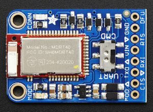
For the communication between the mobile and the RC Car, we are using Adafruit Bluefruit LE UART Friend - BLE module. This module communicates with the SJ2 board through UART at a baud rate of 9600. It also has the capability of working in two modes (data mode and command mode). We can toggle between the two modes using the MOD pin through a GPIO signal or manually using the onboard switch. It supports AT command set, which can be used to control the device's behavior. In data mode, the data written to the UART in the form of a string will be sent through Bluetooth.
Adafruit Bluefruit specifications
- ARM Cortex M0 core running at 16MHz
- 256KB flash memory
- 32KB SRAM
- Transport: UART @ 9600 baud with HW flow control (CTS+RTS required)
- 5V-safe inputs
- On-board 3.3V voltage regulation
- Bootloader with support for safe OTA firmware updates
- Easy AT command set to get up and running quickly
Software Design
Ultrasonic Sensors
We read about the signal interference of adjacent sensors from many of the past projects. So we decided to avoid that interference by triggering two non-adjacent sensors at a time. The FRONT_REAR sensor pair is triggered first. Once both of the sensors compute the distance from the obstacle, then the next pair, RIGHT_LEFT is triggered. For the ultrasonic sensors, we used a separate task instead of the periodic callbacks since this task sleeps on a semaphore which might affect the other functions in the periodic callback function.
SONAR task
void sonar_task(void *p) {
 sonar__init();
 front_rear_echo_received = xSemaphoreCreateBinary();
 left_right_echo_received = xSemaphoreCreateBinary();
 lpc_peripheral__enable_interrupt(LPC_PERIPHERAL__GPIO, sonar__interrupt_dispatcher, "sonar_timing_handler");
 NVIC_EnableIRQ(GPIO_IRQn);
 while (1) {
   sonar__send_trigger_for_10us(FRONT_REAR);
   if (xSemaphoreTake(front_rear_echo_received, 100)) {
     sonar_pair_info[0].distance_from_obstacle_sonar1 = sonar__compute_obstacle_distance_single_sensor(FRONT_SONAR);
     sonar_pair_info[0].distance_from_obstacle_sonar2 = sonar__compute_obstacle_distance_single_sensor(REAR_SONAR);
   }
   vTaskDelay(10);
   sonar__send_trigger_for_10us(LEFT_RIGHT);
   if (xSemaphoreTake(left_right_echo_received, 100)) {
     sonar_pair_info[1].distance_from_obstacle_sonar1 = sonar__compute_obstacle_distance_single_sensor(LEFT_SONAR);
     sonar_pair_info[1].distance_from_obstacle_sonar2 = sonar__compute_obstacle_distance_single_sensor(RIGHT_SONAR);
   }
   sonar__averaging_sensor_values();
 }
}
Bluetooth Module
Bluetooth module is used to send the debug information such as sensor values, current heading, bearing, distance to the destination, and current GPS location to the mobile app. Also, it receives the destination coordinates and start/stop signals from the mobile app. To differentiate between the coordinates and the start/stop signal we used the first char as '@' or '#'. If the starting char is '@', the message contains the destination coordinate. Similarly, "#0' represents the stop signal, and '#1' represents the start signal.
Bluetooth initialization
void bt_module__init(void) {
 line_buffer__init(&line_buffer, line, sizeof(line));
 gpio__construct_with_function(GPIO__PORT_4, 28, GPIO__FUNCTION_2);
 gpio__construct_with_function(GPIO__PORT_4, 29, GPIO__FUNCTION_2);
 uart__init(bt_module_uart_port, clock__get_peripheral_clock_hz(), 9600);
 QueueHandle_t rxq = xQueueCreate(500, sizeof(char));
 QueueHandle_t txq = xQueueCreate(500, sizeof(char));
 uart__enable_queues(bt_module_uart_port, txq, rxq);
 bt_pin__mod = gpio__construct_as_output(GPIO__PORT_0, 15);
 bt_pin__cts = gpio__construct_as_output(GPIO__PORT_0, 18);
 bt_pin__rts = gpio__construct_as_input(GPIO__PORT_2, 9);
 gpio__reset(bt_pin__cts);
 bt_set_mode(bt_data_mode);
}
Bluetooth data handler
static void bt_data_handler__parse_data(char *data) {
 switch (data[0]) {
 case '@':
   bt_data_handler__parse_coordinates(data + 1);
   break;
 case '#':
   bt_data_handler__parse_start_or_stop(data + 1);
   break;
 default:
   break;
 }
}
Technical Challenges
Sensor module
- Issue: Sometimes the front sensor was detecting some obstacles even though there was nothing in front. This may be due to the reception of the reflected signal from the right or left sensor.
- Solution: We included a delay of 10ms in between triggering the first and second pair of sensors.
- Issue: We see some noise in the sensor measurement which makes the car's steering very wobbly.
- Solution: We included a sensor value averaging logic which will return the average of the last 5 readings instead of a single value
Bluetooth module
- Issue: We faced a weird problem in the geo node when computing the distance between the origin and destination. It gave us bizarre values. First, we thought the problem was with the Geo node distance computation formula. But when we trace back the issue, it was with the line buffer initialization in the sensor board. We mistakenly initialized the line buffer with a size of 20 instead of 200. This truncates the coordinates of the destination received (sometimes sets longitude = 0) from the mobile which in turn, affects the distance computation at the Geo node.
- Solution: We initialized the line buffer with a bigger size.
Motor Controller
Hardware Design
Block Diagram
Below is the high-level block diagram of the Meh-Sla Motor Controller system. Originally, the Traxxas RC car came with a TQ Top Qualifier 2.4GHz radio system which gave the PWM signals to the motor controller and steering servo. We hijacked those signals and connected them to the SJ2 board's P2.1 and P2.0, both PWM pins, for the motor and steering, respectively. There are two other PWM pins used to control two flags: a pirate flag and a Meh-Sla flag. Without these flags, our drive to move forward in this project would have halted *wink wink*. Lastly, a RPM sensor (a Hall effect sensor) provides a trigger using a small magnet to P2.6 on the SJ2 board, which will affect the PWM speed sent to the ESC.
Initial Configuration
Initially, the PWM came from this TQ Top Qualifier 2.4GHz radio receiver, which received input from a Traxxas TQ Transmitter (AKA a remote control). When I first took apart the receiver, I had to disconnect the ESC and Steering Servo PWM control, but wanted to leave access to the receiver. I put in temporary female wires to let me switch from SJ2 controlling the system to the transmitter.
Battery Management
The Traxxas RC car came with an 8.4V 3000mAh NiMH power cell, which is used to power the Titan electric motor. Originally, this battery was going to be used to power the rest of the peripherals of the Meh-Sla car (Geo/Sensors/Driver/Motor SJ2 boards), but, after testing the battery life, it was quickly found that there was not enough power and an alternative was needed.
Now the system is equipped with a dual-battery configuration, comprising one battery exclusively for the motor and another dedicated to powering the SJTwo boards and peripherals. This deliberate arrangement ensured an uninterrupted power supply to the controller boards, enabling them to function optimally under all circumstances. The secondary power source for the controller boards consists of a portable 20,000 mAh battery, delivering a reliable 5V output to energize the entire system.
The Traxxas 3000-series Power Cell NiMH battery provided the power for both the brushless motor and the ESC. It was an 8.4V 3000mAh NiMH battery, which came included with the car. There was no need to replace it as it served its purpose effectively.
Software Design
Below are the different modules defined in the motor_board branch (motor_board Gitlab link). There is a module for each of the two PWM pins, P2.1 and P2.0, controlling the motor and steering, respectively. There is a module implementing the RPM hall effect sensor, and a module, argh, which controls the pirate and Meh-Sla flag.
Motor Module (motor.c)
The motor module is simplistic and uses a signal, dbc_MOTOR_SPEED_s, from the Driver board to set the target speed in kph. Before determining what the PWM should be set to, a check for what the current speed is made by using a function from the rpm module, rpm__get_speed(). Then, a simple yet effective proportional algorithm is used to calculate the new target speed in kph. If the phone application has the car turned ON, then a speed_in_percent is set in a global static variable to be used in motor__run_periodic_10Hz(). Additionally, a check is made if the car is going in reverse, as there is a reverse sequence needed to move backward. A state machine could enhance this whole module, but the simplicity worked for our application.
These static helpers calculate the proportional target speed and return a PWM double to control the motor speed. The motor__calculate_motor_pwm() function does not have a check for corner cases as the ESC is not fairly sensitive, and the bounds of what is returned never exceed 10.0 to 20.0 (the range of the ESC's PWM control).
static double motor__calculate_proportional_speed(double target_speed) {
 return (target_speed + (target_speed - rpm__get_speed()));
}
static double motor__calculate_motor_pwm(double speed_in_percent) {
 return neutral_speed_pwm + (max_speed_offset_pwm * speed_in_percent * max_speed_in_percent / 10000);
}
Below is the main function that determined the percent speed to send given a target kph. The method returns a bool for if it is successful or not. This gives the can_handler information on whether the car is turned on or not to light up an LED.
bool motor__motor_speed_pwm(dbc_MOTOR_SPEED_s *motor_speed_s) {
 double speed_in_percent = 0.0;
 bool motor_speed_success = false;
 double target_motor_speed = motor__calculate_proportional_speed(motor_speed_s->DC_MOTOR_DRIVE_SPEED_sig);
 is_reverse = false;
 if (car_on_off) {
   if (target_motor_speed > 15)
     speed_in_percent = 95.0;
   if ((target_motor_speed > 10) & (target_motor_speed <= 15))
     speed_in_percent = 70.0;
   if ((target_motor_speed > 6) & (target_motor_speed <= 10))
     speed_in_percent = 50.0;
   if ((target_motor_speed > 2) & (target_motor_speed <= 6))
     speed_in_percent = 30.0;
   if ((target_motor_speed > -2) & (target_motor_speed <= 2))
     speed_in_percent = -30.0; // brake instead of neutral speed
   if (target_motor_speed <= -2)
     speed_in_percent = -90.0;
   motor_speed_pwm = motor__calculate_motor_pwm(speed_in_percent);
   motor_speed_success = true;
 } else {
   motor_speed_pwm = neutral_speed_pwm;
 }
 return motor_speed_success;
}
Steering Module (steering.c)
The Steering module is very similar to the motor module, but simplified as there is no proportional control to account for. The Steering module takes in a signal, dbc_MOTOR_ANGLE_s and dbc_BRIDGE_APP_COMMANDS_s to control the angle from -45 to 45deg and turn the car on or off, respectively. If the phone application has the car turned ON, then a percent_angle is set in a global static variable to be used in steering__run_periodic_10Hz().
Below is the main function to determine angle of the steering. The method returns a bool for if it is successful or not. This gives the can_handler information on whether the car is turned on or not to light up an LED.
bool steering__servo_angle_pwm(dbc_MOTOR_ANGLE_s *motor_angle_s) {
 double percent_angle = 0.0;
 bool steering_angle_success = false;
 double const current_decoded_motor_angle = motor_angle_s->SERVO_STEER_ANGLE_sig; // -45 to 45deg
 if (car_on_off) {
   if (current_decoded_motor_angle > 30) {
     percent_angle = -100.0; // turn right
   } else if ((current_decoded_motor_angle > 15) & (current_decoded_motor_angle <= 30)) {
     percent_angle = -50.0;
   } else if ((current_decoded_motor_angle > -15) & (current_decoded_motor_angle <= 15)) {
     percent_angle = 0.0;
   } else if ((current_decoded_motor_angle > -30) & (current_decoded_motor_angle <= -15)) {
     percent_angle = 50.0;
   } else if (current_decoded_motor_angle <= -30) {
     percent_angle = 100.0; // turn left
   }
   steering_angle_pwm = steeering__calculate_steering_pwm(percent_angle);
   steering_angle_success = true;
 } else {
   steering_angle_pwm = neutral_steer_angle_pwm;
 }
 return steering_angle_success;
}
RPM Module (rpm.c)
The RPM module is difficult and complex at its core despite the simplicity of the application. The rpm__init() is a bit longer than other inits as a look into the lower level driver modules is needed to: turn on one of the LPC408X peripheral timers, in this case TIMER2, enable a timer counter with a prescalar divider of the clock__get_peripheral_clock_hz(), generate an interrupt on each event (every rotation of the Hall effect sensor), enable interrupts to call an ISR which resets the timer counter back to zero and reset the interrupt, and finally initialize pin P2.6 to the TIMER2 Capture.
void rpm__init(void) {
 // TODO make const uints
 uint32_t const prescalar_divider = 959; // 96MHz clk / 960 divider == 100kHz == 10us
 kph_scalar *= clock__get_peripheral_clock_hz() / (prescalar_divider + 1);
 lpc_peripheral__turn_on_power_to(LPC_PERIPHERAL__TIMER2);
 LPC_TIM2->IR |= 0x3F;
 LPC_TIM2->CCR = (1 << 0) | (1 << 2); // load capture register 0 (CR0) with TC, and generate interrupt on CAPn.0 event
 lpc_peripheral__enable_interrupt(LPC_PERIPHERAL__TIMER2, timer2_isr, NULL);
 LPC_TIM2->PR = prescalar_divider;
 LPC_TIM2->TCR |= (1 << 0); // enable timer counter + prescalar
 gpio__construct_with_function(GPIO__PORT_2, 6, GPIO__FUNCTION_3);
}
Finally, the capture register 0 which stores the time for one rotation, multiplied by kph_scalar (circumference and gear ratio calculation) to determine speed.
void rpm__update_speed_10Hz(void) {
 uint32_t timer_capture_value = LPC_TIM2->CR0;
 if (timer_capture_value == 0) {
   timer_capture_value = 1;
 }
 double const offset = 25000; // used to be 44500
 speed_in_kph = (kph_scalar - offset) / timer_capture_value;
 if ((speed_in_kph < 0.5) || (speed_in_kph > 100)) {
   speed_in_kph = 0.111;
 }
}
Argh Module (argh.c)
The Argh module is simple, and pulls a signal from dbc_GEO_STATUS_s to determine the GEO_STATUS_DISTANCE_TO_DESTINATION. Based on how far away the RC car is from its location, the PWM signal to raise the flag will increase (raise) as the distance decreases. An additional argh__dance_seqeunce() was created for when the location has been reached, but not used as it utilizes delay()'s which span longer than the 10Hz periodic call (resetting the board). A future design can implement a binary semaphor outside of the periodic which sleeps until destination reaches zero, then calls this function from it's own dedicated module file. Pins P2.2 and P2.4 are used for each flag. Argh!
void argh__servo_angle_pwm(dbc_GEO_STATUS_s *geo_status_s) {
 double percent_argh = 0.0;
 current_decoded_distance = geo_status_s->GEO_STATUS_DISTANCE_TO_DESTINATION; // -999m to 0m
 if (current_decoded_distance > 60) {
   percent_argh = -75.0; // flag down
 } else if ((current_decoded_distance > 40) & (current_decoded_distance <= 60)) {
   percent_argh = -25.0;
 } else if ((current_decoded_distance > 20) & (current_decoded_distance <= 40)) {
   percent_argh = 0.0;
 } else if ((current_decoded_distance > 10) & (current_decoded_distance <= 20)) {
   percent_argh = 50.0;
 } else if (current_decoded_distance <= 10) {
   percent_argh = 175.0; // flag up
 }
 argh_pwm = argh__calculate_argh_pwm(percent_argh);
}
void argh__run_periodic_10Hz(void) {
 pwm1__set_duty_cycle(PWM1__2_2, argh_pwm);
 pwm1__set_duty_cycle(PWM1__2_4,
                      argh__calc_opposite_pwm(argh_pwm)); // servo is flipped so need PWM in the other direction
 // if (current_decoded_distance < 2) { // Give semaphor to trigger dance task in main waiting for semaphor
 //   argh__dance_seqeunce();
 // }
}
Technical Challenges
- Issue: Reverse was not working when sending a PWM signal between 10.0 and 15.0.
- Solution: Need to send a signal between 10.0-15.0 to BRAKE first, then signal back to neutral 15.0, then can reverse 10.0-15.0
- Issue: Proportional speed was not working as expected.
- Solution: Proportional can only work as well as it can without also implementing I and D. In our case, a fully-charged battery was a work-around.
Geological Controller
Hardware Design
Compass
The compass we used is from Adafruit, LSM303AGR breakout. It has both a magnetometer and an accelerometer. But, We didn't use the accelerometer which is also needed to properly calibrate the compass because the compass couldn't be aligned exactly parallel to the ground when mounting on a car(instead we used a simple trick - see technical challenges for a detailed description). The compass communicates with the SJ2 board via I2C. It operates on 3.3V. It is a triple-axis accelerometer/magnetometer compass module. The magnetometer is mounted on the car with the Z axis pointing away from the ground and X and Y axis pointing as shown in the image below (we can also switch the x and y, but the formula remains the same). The x and y values shown in the formula correspond to the magnetometer's raw x and y values. The compass should be placed as much as away from all the electronics in the car. We used a PVC pipe to place the compass in an elevated position. Even after the elevated positioning, we faced interference that makes it necessary to calibrate the compass. For the compass calibration, we used a third-party calibration tool. Magneto.
We wrote a simple Python script to visualize how the calibration affects the compass output. The outputs of the Python script show how the compass raw data gets affected after mounting on the car and after calibration.
GPS
The GPS module we used is MTK3339-based breakout from Adafruit. It is interfaced with the SJ2 board through UART. It will output NMEA strings at a default baud rate of 9600. We parsed the latitude and longitude from the GPGGA data and used them to compute the bearing and distance to the destination. In addition to the onboard LED on the GPS breakout board, we also included an external LED for the FIX indication of the GPS module. The onboard FIX LED will blink every second until it gets a FIX. Once it gets a FIX, it will blink once every 15sec. But our external LED will use the inverted logic(Turn OFF once every 15 sec).In addition to that to minimize the time required to get the FIX we also included a coin battery to the GPS module.
Software Design
The Geological Board receives the coordinates of the final destination to be reached, from the CAN bus which is sent from the sensor board. It also gets the current location from the GPS module. Based on these two pieces of information, it computes the bearing angle and distance to the destination using the haversine formula. We can also simply use the Pythagorean theorem since the effect of the curvature of the earth is negligible when the distance is very small. The compass shows the current heading of the vehicle. Once we implemented the basic GPS navigation the waypoints are included. Based on the waypoint algorithm, the appropriate waypoint is selected and the bearing for that point is computed based on the current location of the car. Once the car reaches that waypoint, the next waypoint will be selected and the bearing will be again calculated. The computed waypoints are then transmitted over the CAN bus where the driver board receives them and determine which direction the vehicle needs to steer. Once the distance to the destination is less than 5 meters the bearing and the distance to the destination variables will be set to zero. This indicates to the driver board that the destination is reached and it will send the corresponding command to the motor board.
Compass Calibration
static void compass__calibrate_data(void) {
  const float x_bias = -29.407230;
  const float y_bias = 108.110692;
  const float z_bias = -97.675555;
  // misalignmnet_and_soft_iron_correction_factor
  const float A[3][3] = {
      {1.249033, 0.029467, -0.017773}, {0.029467, 1.362204, -0.047282}, {-0.017773, -0.047282, 1.333366}};

  compass_raw_data.x = A[0][0] * (compass_raw_data.x - x_bias) + A[0][1] * (compass_raw_data.y - y_bias) +
                       A[0][2] * (compass_raw_data.z - z_bias);
  compass_raw_data.y = A[1][0] * (compass_raw_data.x - x_bias) + A[1][1] * (compass_raw_data.y - y_bias) +
                       A[1][2] * (compass_raw_data.z - z_bias);
  compass_raw_data.z = A[2][0] * (compass_raw_data.x - x_bias) + A[2][1] * (compass_raw_data.y - y_bias) +
                       A[2][2] * (compass_raw_data.z - z_bias);
}
GPS data handling
static void gps__transfer_data_from_uart_driver_to_line_buffer(void) {
  char byte;
  const uint32_t zero_timeout = 0;
  if (uart__is_initialized(gps_uart)) {
    while (uart__get(gps_uart, &byte, zero_timeout)) {
      line_buffer__add_byte(&line, byte);
    }
  } else {
    printf("Uart3 is not initialized\n");
  }
}
Geo status dbc signal generation
dbc_GEO_STATUS_s geo_node__determine_heading_bearing_and_distance(void) {
  dbc_GEO_STATUS_s current_geo_status = {0};
  current_geo_status.GEO_STATUS_COMPASS_HEADING = compass__get_current_heading();
  if (!geo_node__arrived_at_destination()) {
    current_geo_status.GEO_STATUS_COMPASS_BEARING = geo_node__compute_current_bearing();
    current_geo_status.GEO_STATUS_DISTANCE_TO_DESTINATION = geo_node__compute_distance_to_destination();
  }
  return current_geo_status;
}
Waypoint Algorithm
The primary purpose of the Waypoint Algorithm is to guide an autonomous car along a predefined route, optimizing its trajectory and ensuring the vehicle adheres to the desired path. The algorithm allows the car to navigate through complex environments by strategically selecting waypoints based on real-time data, such as sensor readings, traffic conditions, and map information. The main objectives of implementing this algorithm in our project include achieving precise localization, efficient path planning, obstacle avoidance, and successful completion of the intended journey.
Our waypoint algorithm utilizes a series of predetermined coordinates known as waypoints to guide the autonomous car from its origin to the final destination. Rather than simply moving in a single direction, the algorithm follows a path that connects these waypoints. The waypoints act as checkpoints along the route, ensuring that the car stays on track. In our project, we have selected 11 waypoints arranged, as shown in the above image.
When the car receives the final coordinates of the destination, the waypoint algorithm is executed on the Geo Controller Node. Its primary objective is to identify the best waypoint for the car to follow. To determine the best waypoint, the algorithm considers two conditions. First, it selects the closest waypoint to the car's current location. Second, it ensures that the distance from this chosen waypoint to the destination is less than the distance between the car's current coordinates and the final coordinates.
Once the algorithm identifies the optimal waypoint, it calculates the bearing, which represents the direction in which the car needs to move in order to reach that waypoint. This bearing information is then relayed to the Driver Node, which provides instructions to the car, guiding it towards the designated waypoint.
In summary, our waypoint algorithm uses predetermined coordinates as checkpoints along the route. It selects the best waypoint based on proximity and ensures that the waypoint brings the car closer to the final destination. By calculating the bearing, the algorithm provides directional instructions to the car, enabling it to navigate towards the specified waypoint effectively.
Technical Challenges
- Issue: The compass behaves perfectly when we test it separately. But once we mount it on the car we receive bizarre values. This is because we didn't calibrate the compass to nullify the hard and soft iron distortion which arises from other components mounted on the car.
- Solution: We did the calibration using a third-party tool.
- Issue: After calibration, we noticed that there is an offset of 70 degrees between the original north and the north pointed by our compass. This may be because the compass was not perfectly aligned parallel to the earth's surface.
- Solution: To solve this issue, we should also include the accelerometer reading from the compass. But instead, we simply added an offset manually in the code. This is because the offset is linear.
- Issue: After fixing the above two problems, we noticed that the compass values are flipped (for example, it shows 5 degrees when the actual degree is 355 degrees).
- Solution: We made a mistake in the conversion of raw value to degree conversion(flipped x and y). Once we fix this, the values seem fine.
- Issue: During our initial GPS testing, we noticed that the GPS returns strings that contain only commas and no valid data. This is because the GPS was still getting to try valid data from at least 3 satellites(not yet get a FIX). This was quite confusing at first since we are not aware that the GPS module has less chance of getting a FIX when working indoors.
- Solution: Do the GPS testing outdoors. If you are doing it indoors, use an external antenna and attach it near the window where there is visibility for a clear sky.
Driver/LCD Controller
Hardware Design
The hardware integration on this board is plain and simple. Like the other boards, the driver board is connected to the CAN bus for communication with the CAN network. In this case, CAN2 is used. The LCD screen used is a SunFounder TWI 1602 Serial LCD Module and is interfaced over an I2C bus through the I2C2 port. All components are tied to a common ground and ran off of the board's 3.3V rail.
Software Design
The driver board is in charge of generating commands to be sent to the motor board over the CAN bus as well as interfacing to the LCD screen to display useful debug data. The software integration consists of a couple of periodic callback functions.
Receive Handling/Data Processing
The primary software task of the driver board is to process incoming sensor data and output commands to be sent to the motor board. This is facilitated in a periodic task running a few key handlers at 10Hz. The high-level task is shown below:
void periodic_callbacks__10Hz(uint32_t callback_count) {
  gpio__toggle(board_io__get_led1());
  can_bus_handler__process_all_received_messages();
  can_bus_handler__transmit_messages();
  driver_mia__manage_mia(10);
}
Using a generic CAN bus handler that leverages the APIs given in can_bus.h, the task first dequeues all received CAN messages and stores them in the private data structures of their corresponding modules. Next, the data is processed, motor commands are generated, and the appropriate messages are sent over the CAN bus. Once all messages are sent, an MIA monitor is run to ensure that messages are being received as expected.
Motor Commands Generation Handler
The generation of the appropriate motor commands follows simple high-level logic: if it is determined that there is an obstacle nearby, the motor commands sent are to circumnavigate the obstacle. If not, the motor commands would reflect the path toward the destination. Then, the commands are sent over the CAN bus.
void motor_commands_handler__generate_motor_commands(void) {
  /**
   * obstacle_avoidance__run_algorithm() detects if there is an obstacle nearby,
   * and if there is, it will generate the necessary motor commands. If not, the
   * motor commands will be generated by the geo data to motor command translation
   * function geo_data__handler_translate_to_motor_commands()
   */
  if (!obstacle_avoidance__run_algorithm()) {
    path_determination__translate_to_motor_commands();
  }
  motor_commands__encode_and_send_over_can_bus();
}
Obstacle Avoidance
Using data received over the CAN bus from the sensor board, the obstacle avoidance algorithm determines whether or not an object is within close proximity to the car, and generates the appropriate motor commands. The pseudocode is as follows:
bool obstacle_avoidance_algorithm() {
  get_sonar_data_from_sonar_handler_module();
  if (any_sensor_reading_below_threshold()) {
    obstacle_is_near = true;
    if (left_is_closer()) {
      steer_based_on_how_close_car_is_to_object(steer_right);
    } else if (right_is_closer()) {
      steer_based_on_how_close_car_is_to_object(steer_left);
    } else if (front_is_closer()) {
      // Arbitrarily choose to steer left if both right and
      // left are equidistant to an object
      steer_based_on_how_close_car_is_to_object(steer_left);
    }
  } else {
    obstacle_is_near = false;
    go_straight();
  }
  calculate_speed_based_on_how_close_front_sensor_is();
  populate_motor_command_structures();
  return obstacle_is_near;
}
Path Determination
If the obstacle avoidance algorithm determines that there are no obstacles nearby, the path determination algorithm runs. The path determination algorithm leverages the data sent from the geological controller. This data includes the current heading of the car, the bearing of the destination based on the current coordinates, and the distance to the destination. Using some simple modular arithmetic, the steering angle can be determined by subtracting heading from bearing. A special case that needs consideration is when the absolute value of the result is greater than 180. This would result in the car taking a longer steering path than needed. To account for this, 360 is either added or subtracted depending on whether the result is positive or negative.
void path_determination__translate_to_motor_commands(void) {
  dbc_GEO_STATUS_s geo_data = geo_data_handler__get_latest_geo_data();
  dbc_MOTOR_ANGLE_s *angle_struct = motor_commands__get_steering_angle_struct_ptr();
  uint16_t bearing = geo_data.GEO_STATUS_COMPASS_BEARING;
  uint16_t heading = geo_data.GEO_STATUS_COMPASS_HEADING;
  int16_t difference = bearing - heading;
  if (abs(difference) > 180) {
    (difference < 0) ? (difference += 360) : (difference -= 360);
  }
  if (abs((int)difference) > 45) {
    if (difference < 0) {
      angle_struct->SERVO_STEER_ANGLE_sig = -45;
    } else {
      angle_struct->SERVO_STEER_ANGLE_sig = 45;
    }
  } else {
    angle_struct->SERVO_STEER_ANGLE_sig = difference;
  }
}
LCD Screen
The LCD screen software implementation is split into a two key modules: a low-level API for controlling the screen itself and an app-specific handler for displaying all of the necessary debug information on the screen
Low-level API
At the lowest level, the screen control API utilizes the I2C API provided in the drivers folder of the SJ2 project. The function to write raw data over the I2C bus is as follows:
void expanderWrite(uint8_t _data) {
  uint8_t data_transfer = ((_data) | _backlightval);
  i2c__write_single(I2C__2, _Addr, 0x00, data_transfer);
}
The upper layers of the API are largely based on an Arduino library for the particular LCD screen that we are using. These layers essentially format basic strings/characters into the appropriate data/commands to be sent to the LCD, giving the user of the API a nice level of abstraction. The upper layers also provide APIs for initializing the display, adjusting settings, and performing actions such as clearing the screen.
App-Specific Handler
The app-specific LCD screen handler leverages this low-level API to write information about the current state of the car to the screen. Due to its lower priority, this is done in a 1Hz periodic task.
The data that the screen prints out is as follows:
- Sonar sensor distance readings (front, back, left, right)
- Heading and Bearing
- Distance to Destination
- Current speed and steering angle being sent to motor board
The LCD handler gets all of this information by utilizing the APIs corresponding to each data field and converting the values and formatting them into strings using the sprintf() function.
static void get_system_stats(void) {
  sonar_sensor_data = sonar_data_handler__get_last_sonar_msg();
  geo_status_data = geo_data_handler__get_latest_geo_data();
  motor_angle_data = *motor_commands__get_steering_angle_struct_ptr();
  motor_speed_data = *motor_commands__get_motor_speed_struct_ptr();
}
void lcd_handler__print_system_stats(void) {
  get_system_stats();
  format_and_print_stat_strings();
}
Technical Challenges
Problem: The car would steer erratically even though there were no objects present.
Solution: This was the result of erroneous/inaccurate readings coming from the ultrasonic sensors. Due to their cheap nature, the problem was not easily avoidable from the hardware side other than mounting the sensors slightly more consistently with one another. To mitigate this issue, a filtering algorithm was implemented on the sensor board. This algorithm averages out the last N sensor readings and sends the resulting value to the motor board. This way, any outlying spikes in sensor readings would not have as drastic of an effect as the non-filtered data. In addition, a longer between the sensors' sampling times was added to avoid sonic interference. The thresholds for obstacle detection were tweaked to be a little lower.
Problem: The car would drive in a "snake-like" pattern in narrower hallways and corridors
Solution: This was the result of a few issues. For one, the thresholds of obstacle detection were not well-balanced. The snaking pattern was the result of the thresholds being too low, allowing the car to get much closer to an obstacle before deciding to turn. As a result, the car would turn much more intensely and would over-steer. On the flip side, having the thresholds too high would result in the car always abiding to the obstacle avoidance algorithm rather than allowing the path determination algorithm to take over. In addition, the steering algorithm was originally rather primitive, only allowing the steering angle to be from a set of fixed values based on the range in which the sensor reading were in. For example, if an object was between 2 - 3 feet away, the steering angle would be ±15 degrees depending if it was on the left or right, it was between 1 - 2 feet, the steering angle the steering angle would be ±25 degrees, and so on. To smooth things out, the steering algorithm was changed to scale the steering algorithm based on the exact distance to an obstacle. Rather than having particular steps, the angle became fully dynamic. This helped a lot with the snaking issue as the car would steer less intensely as it moved away from the obstacle and would straighten out faster.
Problem: The car would slow to a halt too soon.
Solution: The solution to this was similar to the snaking issue, except the scaling algorithm was applied to the speed. This helped a lot not only with slowing down properly, but maintaining a safe speeds from the get go.
Mobile Application
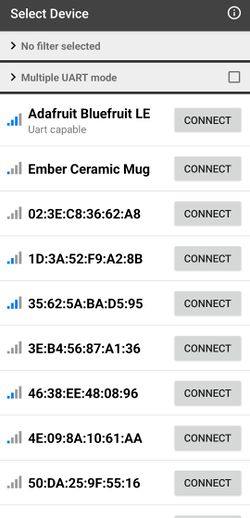 |
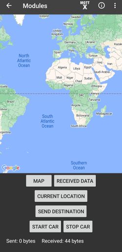 |
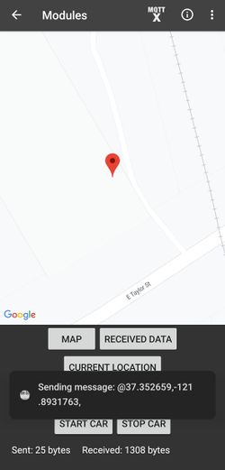 |
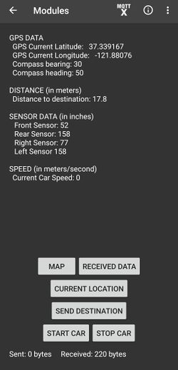 |
Hardware Design
- Android supportive app was developed and was used to run the application.
- Adafruit Bluefruit LE(Bluetooth module) was used to establish communication between the application and the Bridge Controller.
Software Design
- Software used for Mobile App development - Android Studio Flamingo version.
- Coding language- Java
Software Design Flowchart
- Mehsla Connect software design flow is shown below:
Meh-sla connect App Features
- Once we open the Meh-sla connect app, we can see the list of available bluetooth devices.
- Connect to the Adafruit Bluefruit LE module and once connected we can see the features of the app.
- "CURRENT LOCATION" button - Locates our current location. Just long press anywhere on the map to set as destination.
- "SEND DESTINATION" - Sends the destination latitude and longitude to the Bluetooth module.
- "START CAR" - Sends '1' to the bluetooth module from where the bridge sends it to the motor to start the car.
- "STOP CAR" - Sends '0' to the bluetooth module from where the bridge sends it to the motor to stop the car.
- "RECEIVED DATA" - Displays the debug information of the car.
- "MAP" - Takes back from the display data UI to the map UI to pick location.
Technical Challenges
- Issue: Connecting the Bluetooth module and the App. Initially for a week, though the adafruit bluetooth module was getting listed in available devices, we weren't able to connect to the module.
- Solution: Note down the MAC address, and UUID of the Bluetooth module you use.
- Issue: If you don't have prior experience in Mobile App development like setting up an account in the Google Cloud console, enabling the API, and using the API key in the Android studio App Manifest file.
- Solution: Read through the Developer's website. Also, make sure you enable all the privacy settings for accessing the Google Maps SDK.
- Issue: While displaying the data in the mobile app, we found that the data was not consistent enough as we failed to check the debug information data before we send it.
- Solution: Use CAN Bus Master to check if you receive the required debug data as expected and then ensure you send the data as a complete frame. Also, make sure to include an algorithm to receive and split the data before displaying it.
Conclusion
The Meh-Sla RC car came together because of the hard-work and determination of the entire team. Any more or fewer people would have taken away from the perfect team dynamic that led to each prototype miraculously working each following demo day. Everyone took charge of their system and made an active effort to work outside of class (and each weekend meet-up) to ensure their modules/functions/git contributions were working and communicated any issues on WhatsApp. It is difficult to manage the schedules of everyone's lives, especially considering out-of-school responsibilities, but the professor, Preet, provided a background and environment for students to transition away from just working on this project to enjoying this project.
If you are a future CMPE243 student, or anyone interested in starting this project from scratch, take pictures and never forget each moment of the process. Your teammates will become your friends through the debugging and issues that arise in the project. You will find joy (and maybe a few tears) in sharing the difficulties of the project with one another, but that should never take away from the passion that will grow from working on this project.
We are all proud of the system we made. We are all happy with the work we have done. We are ecstatic that it is all over! But, we will never forget this project and the fun that we shared!
What We Learned
- The CAN bus is an excellent protocol for effectively organizing message transmission and reception within a system.
- A complex project like an autonomous car can be broken down into smaller much simpler parts
- The simplest solution can often be the most effective for solving a problem.
- Only one person should work on a branch at a time.
- The more you plan at the beginning, the smoother things go because everyone has an understanding of who is doing what.
- This also allowed for each other to identify if someone was falling behind and needed help.
Project Video
Project Source Code
Advice for Future Students
- Plan out the project before you start working on it
- Make SW and HW Block Diagrams
- Review the wiki pages for all of the previous groups
- Focus on Advice and Challenges Sections
- Don't write bugs in your code
- The time spent fixing bugs could be used for implementing extra features
- Plan to meet in a group for 4-5 hours every weekend for system integration
- This should NOT be the only time spent on the project! Everyone should be working throughout the week individually.
- Don't over-engineer your code
- DON'T FORGET GROUND FOR PWM/PCAN/POWER!!!
- Be the Best-sla that you can be!
Acknowledgement
Without Preet, this project would not have existed.
References
- HC-SR04 datasheet
- Bearing and Distance computation formulas
- Bluetooth Tutorial
- Compass datasheet
- GPS tutorial
- Compass calibration tutorial
- Compass calibration tool
