Difference between revisions of "S23: CAN CLAN"
(→Introduction) |
(→Project Video) |
||
| (149 intermediate revisions by the same user not shown) | |||
| Line 1: | Line 1: | ||
== CAN CLAN == | == CAN CLAN == | ||
| − | [[File: | + | [[File:RC_Car0.jpg |800px|middle ]] |
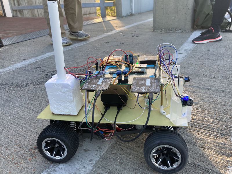
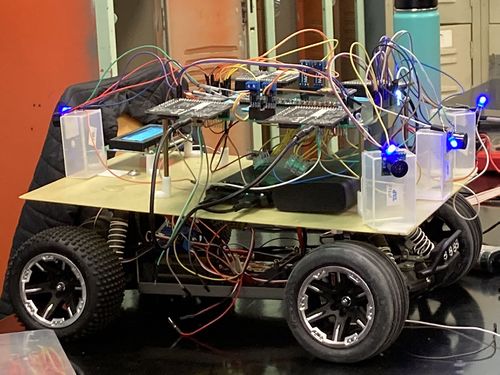
Picture of the RC Car | Picture of the RC Car | ||
<HR> | <HR> | ||
| Line 6: | Line 6: | ||
== Abstract == | == Abstract == | ||
| − | + | Our goal for this project is to use knowledge we gathered from lectures to design, implement, and test a self-driving RC car using a Controller Area Network (CAN) bus for controller communication. The project involves FreeRTOS and utilizes periodic tasks (running at 1Hz, 10Hz, and 100Hz) to gather, process, and display data from various embedded modules. | |
| + | |||
=== Introduction === | === Introduction === | ||
| Line 12: | Line 13: | ||
The project was divided into 5 modules: | The project was divided into 5 modules: | ||
| − | * Sensor | + | * Sensor Information |
| − | * Motor | + | * Motor Operation |
| − | * | + | * Geological Information |
| − | * Driver | + | * Driver & LCD Manager |
| − | * | + | * Bridge & Android Application |
| + | |||
=== Team Members & Responsibilities === | === Team Members & Responsibilities === | ||
| − | |||
<div><ul> | <div><ul> | ||
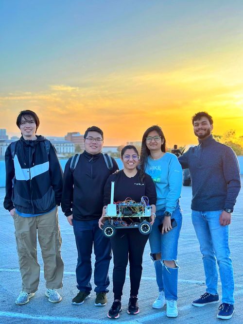
| − | <li style="display: inline-block;">[[File: | + | <li style="display: inline-block;">[[File:group_snap.jpg |500px|middle ]] </li> |
</ul></div> | </ul></div> | ||
| Line 27: | Line 28: | ||
<BR/> | <BR/> | ||
| − | <li style="display: inline-block;">[[File: | + | <li style="display: inline-block;">[[File:Rashmi_snap.jpg |200px|middle ]]</li> |
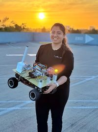
| − | <font color="black"> '''Rashmi | + | <font color="black"> '''[https://www.linkedin.com/in/rashmiv7/ Rashmi Vaidya] |
| + | * Driver Controller | ||
| + | * Motor Controller | ||
* Geo Controller | * Geo Controller | ||
| − | * GPS | + | * GPS Interfacing |
| + | * Mobile App | ||
* Integration Testing | * Integration Testing | ||
| − | |||
| − | <li style="display: inline-block;">[[File: | + | <li style="display: inline-block;">[[File:Zeel.jpg |200px|middle ]]</li> |
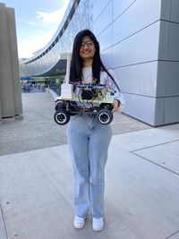
<font color="black"> '''Zeel Jatinkumar Lia | <font color="black"> '''Zeel Jatinkumar Lia | ||
| − | * | + | * Sensor and Bridge Controller |
| − | * | + | * Ultrasonic sensors |
| + | * LCD interfacing | ||
* Integration Testing | * Integration Testing | ||
| − | |||
| − | <li style="display: inline-block;">[[File: | + | <li style="display: inline-block;">[[File:Priyam.jpg |200px|middle ]]</li> |
<font color="black"> '''Priyam Hajisheth | <font color="black"> '''Priyam Hajisheth | ||
| − | * | + | * Hardware mounting |
| − | * | + | * Mobile App |
* Integration Testing | * Integration Testing | ||
| − | |||
| − | <li style="display: inline-block;">[[File: | + | <li style="display: inline-block;">[[File:Xinyu.jpg |200px|middle ]]</li> |
<font color="black"> '''Xinyu He | <font color="black"> '''Xinyu He | ||
| − | * | + | * Hardware solution |
| + | * Wiki Page Update | ||
* Integration Testing | * Integration Testing | ||
| − | |||
| − | |||
| − | <li style="display: inline-block;">[[File: | + | <li style="display: inline-block;">[[File:hongjing.jpg |200px|middle ]]</li> |
<font color="black"> '''Hongjin Cheng | <font color="black"> '''Hongjin Cheng | ||
| − | * | + | * Protoboard soldering and Hardware assembling |
| − | * | + | * Compass, RPM Sensor, DC and servo motor interfacing |
| − | |||
* Integration Testing | * Integration Testing | ||
| − | |||
<HR> | <HR> | ||
| Line 155: | Line 154: | ||
* '''MILESTONE - Basic car driving ability with basic obstacle avoidance''' | * '''MILESTONE - Basic car driving ability with basic obstacle avoidance''' | ||
| | | | ||
| − | *<font color = " | + | *<font color = "green"> Completed |
|- | |- | ||
! scope="row"| 7 | ! scope="row"| 7 | ||
| Line 170: | Line 169: | ||
* '''MILESTONE - Integrated, reliably "heading" towards provided destination bearing, basic obstacle avoidance''' | * '''MILESTONE - Integrated, reliably "heading" towards provided destination bearing, basic obstacle avoidance''' | ||
| | | | ||
| − | *<font color = " | + | *<font color = "green"> Completed |
|- | |- | ||
! scope="row"| 8 | ! scope="row"| 8 | ||
| Line 185: | Line 184: | ||
* '''MILESTONE - Integration part 2, perform obstacle avoidance and destination bearing''' | * '''MILESTONE - Integration part 2, perform obstacle avoidance and destination bearing''' | ||
| | | | ||
| − | *<font color = " | + | *<font color = "green"> Completed |
|- | |- | ||
! scope="row"| 9 | ! scope="row"| 9 | ||
| Line 197: | Line 196: | ||
* '''MILESTONE - Integration and outdoor testing, adding necessary software changes''' | * '''MILESTONE - Integration and outdoor testing, adding necessary software changes''' | ||
| | | | ||
| − | *<font color = " | + | *<font color = "green"> Completed |
|- | |- | ||
! scope="row"| 10 | ! scope="row"| 10 | ||
| Line 209: | Line 208: | ||
* '''MILESTONE - Integration testing, deal with uneven terrain, reliable waypoints navigation and obstacle avoidance''' | * '''MILESTONE - Integration testing, deal with uneven terrain, reliable waypoints navigation and obstacle avoidance''' | ||
| | | | ||
| − | *<font color = " | + | *<font color = "green"> Completed |
|- | |- | ||
! scope="row"| 11 | ! scope="row"| 11 | ||
| Line 218: | Line 217: | ||
* '''Full System Testing, any needed Hardware and software fixes and optimizing ''' | * '''Full System Testing, any needed Hardware and software fixes and optimizing ''' | ||
| | | | ||
| − | *<font color = " | + | *<font color = "green"> Completed |
|- | |- | ||
! scope="row"| 11 | ! scope="row"| 11 | ||
| − | | 05/ | + | | 05/23/2023 |
| − | | 05/ | + | | 05/23/2023 |
| | | | ||
* '''Final Project Demo Day ''' | * '''Final Project Demo Day ''' | ||
| | | | ||
| − | *<font color = " | + | *<font color = "green"> Completed |
|- | |- | ||
|} | |} | ||
| Line 237: | Line 236: | ||
|- | |- | ||
! scope="col"| Item# | ! scope="col"| Item# | ||
| − | ! scope="col"| Part | + | ! scope="col"| Part Desciption |
! scope="col"| Vendor | ! scope="col"| Vendor | ||
! scope="col"| Qty | ! scope="col"| Qty | ||
| Line 243: | Line 242: | ||
|- | |- | ||
! scope="row"| 1 | ! scope="row"| 1 | ||
| − | | | + | | RC Car |
| − | | | + | | Traxxas [https://www.hobbytown.com/san-jose-ca/l194] |
| 1 | | 1 | ||
| − | | $ | + | | $251.51 |
|- | |- | ||
! scope="row"| 2 | ! scope="row"| 2 | ||
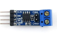
| − | | | + | | CAN Transceivers |
| − | | | + | | Amazon [https://www.amazon.com/dp/B00KM6XMXO?psc=1&ref=ppx_pop_dt_b_product_details] |
| − | | | + | | 4 |
| − | | $ | + | | $43.72 |
|- | |- | ||
! scope="row"| 3 | ! scope="row"| 3 | ||
| − | | | + | | SJ-2 Board |
| − | | | + | | |
| − | | | + | | 4 |
| − | | $ | + | | $200.00 |
|- | |- | ||
! scope="row"| 4 | ! scope="row"| 4 | ||
| + | | LV-MaxSonar-EZ1 Ultrasonic Range Finder | ||
| + | | Amazon [https://www.amazon.com/dp/B00A7YGVJI?psc=1&ref=ppx_pop_dt_b_product_details] | ||
| + | | 4 | ||
| + | | $131.20 | ||
| + | |- | ||
| + | ! scope="row"| 5 | ||
| + | | GPS | ||
| + | | Amazon [https://www.amazon.com/your-orders/pop/ref=ppx_yo_dt_b_pop?_encoding=UTF8&gen=canonical&lineItemId=pljlnsjonpksuny&orderId=114-1314271-4720267&packageId=1&returnSummaryId=&returnUnitIndices=&returnUnitMappingId=&shipmentId=M4GFQmHt8] | ||
| + | | 1 | ||
| + | | $10.99 | ||
| + | |- | ||
| + | ! scope="row"| 6 | ||
| + | | RPM Sensor | ||
| + | | Amazon [https://www.amazon.com/gp/product/B006IRXEZM/ref=ppx_od_dt_b_asin_title_s01?ie=UTF8&psc=1] | ||
| + | | 1 | ||
| + | | $16.76 | ||
| + | |- | ||
| + | ! scope="row"| 7 | ||
| + | | Buletooth | ||
| + | | Amazon[https://www.amazon.com/gp/product/B07VL725T8/ref=ppx_od_dt_b_asin_title_s01?ie=UTF8&psc=1] | ||
| + | | 1 | ||
| + | | $15.99 | ||
| + | |- | ||
| + | ! scope="row"| 8 | ||
| + | | LCD Display | ||
| + | | Amazon [https://www.amazon.com/dp/B07QLRD3TM?psc=1&ref=ppx_pop_dt_b_product_details] | ||
| + | | 1 | ||
| + | | $10.99 | ||
| + | |- | ||
| + | ! scope="row"| 9 | ||
| + | | Battery/Charger | ||
| + | | | ||
| + | | 1 | ||
| + | | $62.95 | ||
| + | |- | ||
| + | ! scope="row"| 10 | ||
| + | | Cable | ||
| + | | Amazon [https://www.amazon.com/gp/product/B095JZSHXQ/ref=ppx_yo_dt_b_asin_title_o00_s00?ie=UTF8&th=1] | ||
| + | | 1 | ||
| + | | $7.99 | ||
| + | |- | ||
| + | ! scope="row"| 11 | ||
| + | | LSM303AGR Compass | ||
| + | | Adafruit [https://kjdelectronics.com/products/adafruit-lsm303agr-accelerometer-magnetometer-stemma-qt-qwiic?variant=39900146827382¤cy=USD&utm_medium=product_sync&utm_source=google&utm_content=sag_organic&utm_campaign=sag_organic&utm_campaign=gs-2019-05-19&utm_source=google&utm_medium=smart_campaign&gclid=CjwKCAjw6vyiBhB_EiwAQJRopno9PMnrn52CxOxkIiaSrYQ5L28xbsOLGAy92vVnEQrwJI19ORICLRoCKy8QAvD_BwE] | ||
| + | | 1 | ||
| + | | $19.57 | ||
| + | |- | ||
| + | ! scope="row"| 12 | ||
| + | | Magnet holder | ||
| + | | | ||
| + | | 1 | ||
| + | | $8.09 | ||
| + | |- | ||
| + | ! scope="row"| 13 | ||
| + | | 2*20 header | ||
| | | | ||
| − | |||
| 1 | | 1 | ||
| − | | $ | + | | $7.59 |
|- | |- | ||
| − | ! scope="row"| | + | ! scope="row"| 14 |
| + | | RPM holder | ||
| + | | | ||
| + | | 1 | ||
| + | | $7.73 | ||
| + | |- | ||
| + | ! scope="row"| 15 | ||
| + | | long stand off | ||
| + | | | ||
| + | | 1 | ||
| + | | $2.21 | ||
| + | |- | ||
| + | ! scope="row"| 16 | ||
| + | | Mount board | ||
| | | | ||
| − | |||
| 1 | | 1 | ||
| − | | | + | | None |
|- | |- | ||
| − | ! scope="row"| | + | ! scope="row"| 17 |
| + | | Protoboard | ||
| | | | ||
| − | |||
| 1 | | 1 | ||
| − | | | + | | None |
|- | |- | ||
| − | ! scope="row"| | + | ! scope="row"| 18 |
| + | | Small stand off | ||
| + | | | ||
| + | | | ||
| + | | None | ||
| + | |- | ||
| + | ! scope="row"| 19 | ||
| + | | Pin header | ||
| + | | | ||
| + | | | ||
| + | | None | ||
| + | |- | ||
| + | ! scope="row"| 20 | ||
| + | | Switch for DC motor | ||
| | | | ||
| − | |||
| 1 | | 1 | ||
| − | | | + | | None |
|- | |- | ||
| − | ! scope="row"| | + | ! scope="row"| 21 |
| + | | wire connectors | ||
| | | | ||
| − | |||
| 1 | | 1 | ||
| − | | | + | | None |
| + | |- | ||
|} | |} | ||
| Line 295: | Line 373: | ||
== Printed Circuit Board == | == Printed Circuit Board == | ||
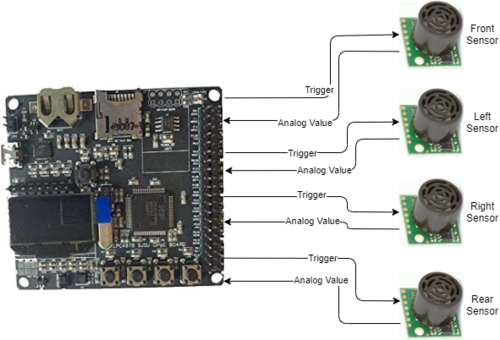
| − | + | The Following table indicate the pin connection of all Hardware . | |
| − | + | ||
| + | [[File:CAN_CLAN_Car_Pinout.png|1000px|middle]] | ||
| + | |||
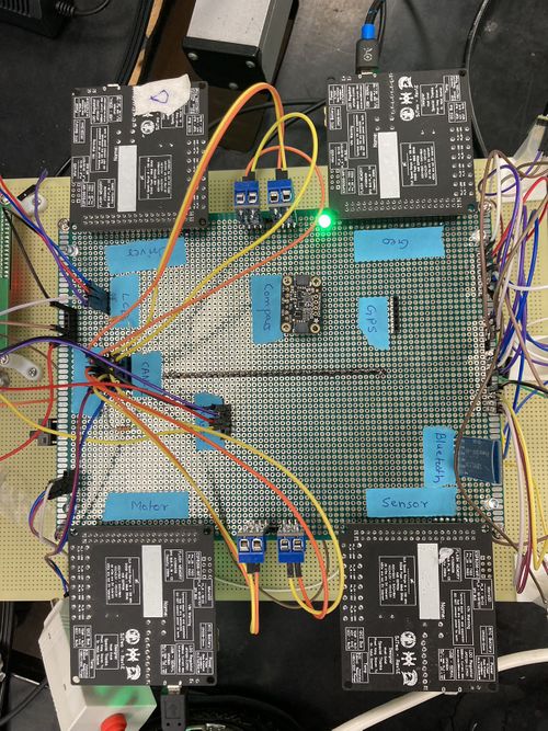
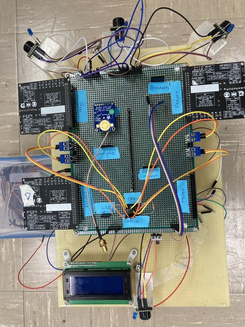
| + | This is the pictures show protoboard and the mount board. | ||
| + | |||
| + | [[File:Printed_Circuit_Board1.jpg|500px|Image: 250 pixels]][[File:Printed_Circuit_Board2.jpg|500px|Image: 250 pixels]] | ||
<HR> | <HR> | ||
<BR/> | <BR/> | ||
| + | |||
== CAN Communication == | == CAN Communication == | ||
<Talk about your message IDs or communication strategy, such as periodic transmission, MIA management etc.> | <Talk about your message IDs or communication strategy, such as periodic transmission, MIA management etc.> | ||
| − | + | We are using 100HZ for CAN bus communication, 50HZ for sensors, 10HZ for calculation, 1HZ for printing. The following table shows the Message ID. | |
| + | {| class="wikitable" | ||
| + | |- | ||
| + | ! scope="col"| | ||
| + | ! scope="col"| Node | ||
| + | ! scope="col"| Message ID | ||
| + | |- | ||
| + | ! scope="row"| 1 | ||
| + | | ULTRASONIC_TO_DRIVER | ||
| + | | 100 | ||
| + | |- | ||
| + | ! scope="row"| 2 | ||
| + | | GPS_DESTINATION | ||
| + | | 300 | ||
| + | |- | ||
| + | ! scope="row"| 3 | ||
| + | | DRIVE_STATUS_CMD | ||
| + | | 50 | ||
| + | |- | ||
| + | ! scope="row"| 4 | ||
| + | | SELF_TEST_CMD | ||
| + | | 600 | ||
| + | |- | ||
| + | ! scope="row"| 5 | ||
| + | | DRIVER_TO_MOTOR | ||
| + | | 200 | ||
| + | |- | ||
| + | ! scope="row"| 6 | ||
| + | | DRIVER_SELF_TEST_RESULT | ||
| + | | 610 | ||
| + | |- | ||
| + | ! scope="row"| 7 | ||
| + | | GEO_STATUS | ||
| + | | 400 | ||
| + | |- | ||
| + | ! scope="row"| 8 | ||
| + | | GEO_SELF_TEST_RESULT | ||
| + | | 620 | ||
| + | |- | ||
| + | ! scope="row"| 9 | ||
| + | | GEO_CURRENT_COORDS | ||
| + | | 650 | ||
| + | |- | ||
| + | ! scope="row"| 10 | ||
| + | | MOTOR_TO_APP_DBG | ||
| + | | 500 | ||
| + | |- | ||
| + | |} | ||
=== Hardware Design === | === Hardware Design === | ||
<Show your CAN bus hardware design> | <Show your CAN bus hardware design> | ||
| + | |||
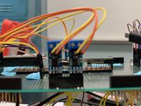
| + | [[File:CAN_Transiver0.png|200px]][[File:CAN_Transiver1.jpg|200px]] | ||
| + | |||
| + | |||
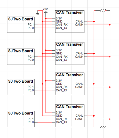
| + | *The following is the CAN Transceiver Design logicwork. | ||
| + | [[File:CAN_Transiver_Design.png|400px]] | ||
=== DBC File === | === DBC File === | ||
| Line 311: | Line 448: | ||
<You can optionally use an inline image> | <You can optionally use an inline image> | ||
| + | <pre> | ||
| + | VERSION "" | ||
| + | |||
| + | NS_ : | ||
| + | BA_ | ||
| + | BA_DEF_ | ||
| + | BA_DEF_DEF_ | ||
| + | BA_DEF_DEF_REL_ | ||
| + | BA_DEF_REL_ | ||
| + | BA_DEF_SGTYPE_ | ||
| + | BA_REL_ | ||
| + | BA_SGTYPE_ | ||
| + | BO_TX_BU_ | ||
| + | BU_BO_REL_ | ||
| + | BU_EV_REL_ | ||
| + | BU_SG_REL_ | ||
| + | CAT_ | ||
| + | CAT_DEF_ | ||
| + | CM_ | ||
| + | ENVVAR_DATA_ | ||
| + | EV_DATA_ | ||
| + | FILTER | ||
| + | NS_DESC_ | ||
| + | SGTYPE_ | ||
| + | SGTYPE_VAL_ | ||
| + | SG_MUL_VAL_ | ||
| + | SIGTYPE_VALTYPE_ | ||
| + | SIG_GROUP_ | ||
| + | SIG_TYPE_REF_ | ||
| + | SIG_VALTYPE_ | ||
| + | VAL_ | ||
| + | VAL_TABLE_ | ||
| + | |||
| + | BS_: | ||
| + | |||
| + | BU_: DBG DRIVER GEO MOTOR SENSOR_BRIDGE | ||
| + | |||
| + | |||
| + | BO_ 100 ULTRASONIC_TO_DRIVER: 5 SENSOR_BRIDGE | ||
| + | SG_ ULTRASONIC_TO_DRIVER_left : 0|10@1+ (1,0) [0|511] "cm" DRIVER | ||
| + | SG_ ULTRASONIC_TO_DRIVER_right : 10|10@1+ (1,0) [0|511] "cm" DRIVER | ||
| + | SG_ ULTRASONIC_TO_DRIVER_front : 20|10@1+ (1,0) [0|511] "cm" DRIVER | ||
| + | SG_ ULTRASONIC_TO_DRIVER_back : 30|10@1+ (1,0) [0|511] "cm" DRIVER | ||
| + | |||
| + | BO_ 300 GPS_DESTINATION: 8 SENSOR_BRIDGE | ||
| + | SG_ GPS_DEST_LATITUDE_SCALED_100000 : 0|32@1- (1,0) [0|0] "Degrees" GEO | ||
| + | SG_ GPS_DEST_LONGITUDE_SCALED_100000 : 32|32@1- (1,0) [0|0] "Degrees" GEO | ||
| + | |||
| + | BO_ 50 DRIVE_STATUS_CMD: 1 SENSOR_BRIDGE | ||
| + | SG_ DRIVE_STATUS_CMD_start : 0|1@1+ (1,0) [0|0] "" MOTOR | ||
| + | |||
| + | BO_ 600 SELF_TEST_CMD: 1 SENSOR_BRIDGE | ||
| + | SG_ SELF_TEST_CMD_start : 0|1@1+ (1,0) [0|0] "" MOTOR, GEO, DRIVER | ||
| + | |||
| + | |||
| + | BO_ 200 DRIVER_TO_MOTOR: 2 DRIVER | ||
| + | SG_ DRIVER_TO_MOTOR_steer : 0|8@1- (1,0) [0|0] "degrees" MOTOR, SENSOR_BRIDGE | ||
| + | SG_ DRIVER_TO_MOTOR_speed : 8|8@1- (1,0) [0|50] "mph" MOTOR, SENSOR_BRIDGE | ||
| + | |||
| + | BO_ 610 DRIVER_SELF_TEST_RESULT: 1 DRIVER | ||
| + | SG_ DRIVER_SELF_TEST_RESULT_status : 0|8@1+ (1,0) [0|0] "" SENSOR_BRIDGE | ||
| + | BO_ 400 GEO_STATUS: 8 GEO | ||
| + | SG_ GEO_STATUS_COMPASS_HEADING : 0|12@1+ (1,0) [0|359] "Degrees" DRIVER, SENSOR_BRIDGE | ||
| + | SG_ GEO_STATUS_COMPASS_BEARING : 12|12@1+ (1,0) [0|359] "Degrees" DRIVER, SENSOR_BRIDGE | ||
| + | SG_ GEO_STATUS_DISTANCE_TO_DESTINATION : 24|16@1+ (0.1,0) [0|0] "Meters" DRIVER, SENSOR_BRIDGE | ||
| + | SG_ GEO_STATUS_SATELLITE_LOCKED : 40|1@1+ (1,0) [0|0] "" DRIVER, SENSOR_BRIDGE | ||
| + | |||
| + | BO_ 620 GEO_SELF_TEST_RESULT: 1 GEO | ||
| + | SG_ GEO_SELF_TEST_RESULT_status : 0|8@1+ (1,0) [0|0] "" SENSOR_BRIDGE | ||
| + | |||
| + | BO_ 650 GEO_CURRENT_COORDS: 8 SENSOR_BRIDGE | ||
| + | SG_ CURR_LATITUDE_SCALED_100000 : 0|32@1- (1,0) [0|0] "Degrees" SENSOR_BRIDGE | ||
| + | SG_ CURR_LONGITUDE_SCALED_100000 : 32|32@1- (1,0) [0|0] "Degrees" SENSOR_BRIDGE | ||
| + | |||
| + | |||
| + | BO_ 500 MOTOR_TO_APP_DBG: 2 MOTOR | ||
| + | SG_ MOTOR_TO_APP_DBG_current_steer : 0|8@1- (1,0) [0|0] "degrees" SENSOR_BRIDGE | ||
| + | SG_ MOTOR_TO_APP_DBG_current_speed : 8|8@1- (1,0) [0|50] "mph" SENSOR_BRIDGE | ||
| + | |||
| + | BO_ 620 MOTOR_SELF_TEST_RESULT: 1 MOTOR | ||
| + | SG_ MOTOR_SELF_TEST_RESULT_status : 0|8@1+ (1,0) [0|0] "" SENSOR_BRIDGE | ||
| + | |||
| + | |||
| + | CM_ BU_ DRIVER "The LED display and driver controller driving the car"; | ||
| + | CM_ BU_ MOTOR "The RPM sensor, DC and servo motor controller of the car"; | ||
| + | CM_ BU_ SENSOR_BRIDGE "The Bluetooth and the sonar sensor controller of the car"; | ||
| + | CM_ BU_ GEO "The GPS and compass sensor controller of the car"; | ||
| + | |||
| + | BA_DEF_ "BusType" STRING ; | ||
| + | BA_DEF_ BO_ "GenMsgCycleTime" INT 0 0; | ||
| + | BA_DEF_ SG_ "FieldType" STRING ; | ||
| + | |||
| + | BA_DEF_DEF_ "BusType" "CAN"; | ||
| + | BA_DEF_DEF_ "FieldType" ""; | ||
| + | BA_DEF_DEF_ "GenMsgCycleTime" 0; | ||
| + | |||
| + | BA_ "GenMsgCycleTime" BO_ 100 1000; | ||
| + | BA_ "GenMsgCycleTime" BO_ 200 50; | ||
| + | |||
| + | </pre> | ||
<HR> | <HR> | ||
<BR/> | <BR/> | ||
| + | |||
== Sensor ECU == | == Sensor ECU == | ||
<Picture and link to Gitlab> | <Picture and link to Gitlab> | ||
| + | [https://gitlab.com/rashmi_sv/the_CAN_clan/-/tree/main/projects/lpc40xx_sensor/l5_application/ultrasonic Sensor Node GitLab] | ||
| + | |||
| + | [[File:Sensor00.png|200px]][[File:Sensor1.jpg|200px]] | ||
| + | |||
| + | <li style="display: inline-block;"> [[File:Sensor_Node.png|500px|thumb|centre|]] </li> | ||
| + | |||
| + | |||
=== Hardware Design === | === Hardware Design === | ||
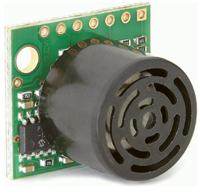
| + | '''LV-MaxSonar-EZ1 Ultrasonic Range Finder''' | ||
| + | |||
| + | *MaxSonar-EZ1 detects objects from 0" to 254". | ||
| + | *2.5-5.5V operation range. Low 2mA supply current. | ||
| + | *42kHz Ultrasonic sensor with 20Hz reading rate. | ||
| + | *Incredibly Small Package Sonar Range Finder. | ||
| + | *Serial Output, PWM output, Analog Output. | ||
| + | |||
| + | '''Sensor Design''' | ||
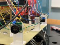
| + | *We used 4 sensors-LV-MaxSonar-EZ1 Ultrasonic Range Finder. These ultrasonic sensors are used by the RC car for the purpose of obstacle avoidance. Three sensors were placed on the front side of the RC car and one on the back. They use I2C communication to send distance data to the SJ2 microcontroller. On the SJ2 microcontroller, P0.10 was used for SDA, and P0.11 was used for SCL. It takes in +5V supply voltage. A LED is soldering on sensors to indicate if the sensor is working well. | ||
| + | |||
=== Software Design === | === Software Design === | ||
<List the code modules that are being called periodically.> | <List the code modules that are being called periodically.> | ||
| + | *Sensors are divided into two groups: | ||
| + | *1. Front-rear group | ||
| + | *2. Left-right group | ||
| + | Each group use 50HZ. The following code shows how it being called periodically. | ||
| + | <syntaxhighlight lang="cpp"> | ||
| + | void periodic_callbacks__100Hz(uint32_t callback_count) { | ||
| + | CAN_RX_MSGS_FOR_BRIDGE(); | ||
| + | Sensor_Controller__100hz_handler(callback_count); | ||
| + | can_ultrasonic_sensor_transmit_messages(); | ||
| + | } | ||
| + | </syntaxhighlight> | ||
| + | <br> | ||
| + | The following is the code for sensor controller. | ||
| + | <syntaxhighlight lang="cpp"> | ||
| + | #include "LV_sensor_controller.h" | ||
| + | #include "LV_sensor_pin_init.h" | ||
| + | |||
| + | static dbc_ULTRASONIC_TO_DRIVER_s ultra_sonic_data; | ||
| + | |||
| + | static gpio_s FRONT_OBSTACLE_LED; | ||
| + | static gpio_s LEFT_OBSTACLE_LED; | ||
| + | static gpio_s RIGHT_OBSTACLE_LED; | ||
| + | static gpio_s BACK_OBSTACLE_LED; | ||
| + | |||
| + | void Sensor_Controller_init(void) { | ||
| + | FRONT_OBSTACLE_LED = gpio__construct_as_output(GPIO__PORT_2, 2); | ||
| + | LEFT_OBSTACLE_LED = gpio__construct_as_output(GPIO__PORT_2, 0); | ||
| + | RIGHT_OBSTACLE_LED = gpio__construct_as_output(GPIO__PORT_2, 1); | ||
| + | BACK_OBSTACLE_LED = gpio__construct_as_output(GPIO__PORT_2, 4); | ||
| + | adc_init_for_LV_sensors(); | ||
| + | trigger_pins_for_LV_sensors(); | ||
| + | } | ||
| + | |||
| + | void Sensor_Controller__print_sensor_values() { | ||
| + | printf("L:%d F:%d R:%d B:%d\n", ultra_sonic_data.ULTRASONIC_TO_DRIVER_left, | ||
| + | ultra_sonic_data.ULTRASONIC_TO_DRIVER_front, ultra_sonic_data.ULTRASONIC_TO_DRIVER_right, | ||
| + | ultra_sonic_data.ULTRASONIC_TO_DRIVER_back); | ||
| + | } | ||
| + | |||
| + | static void update_obstacle_LED(int sensor_value, gpio_s obstacle_led) { | ||
| + | if (sensor_value > 100) { // no obstacle detected. Turn OFF LED | ||
| + | gpio__reset(obstacle_led); | ||
| + | } else { | ||
| + | gpio__set(obstacle_led); // obstacle detected. Turn ON LED | ||
| + | } | ||
| + | } | ||
| + | |||
| + | void Sensor_Controller__100hz_handler(uint32_t callback_count) { | ||
| + | if (callback_count % 2 == 0) { | ||
| + | collect_left_LV_sensor_values_buffer(); | ||
| + | ultra_sonic_data.ULTRASONIC_TO_DRIVER_left = sort_sensor_buffer_data_and_get_median(LEFT_ULTRA_SONIC); | ||
| + | update_obstacle_LED(ultra_sonic_data.ULTRASONIC_TO_DRIVER_left, LEFT_OBSTACLE_LED); | ||
| + | |||
| + | collect_right_LV_sensor_values_buffer(); | ||
| + | ultra_sonic_data.ULTRASONIC_TO_DRIVER_right = sort_sensor_buffer_data_and_get_median(RIGHT_ULTRA_SONIC); | ||
| + | update_obstacle_LED(ultra_sonic_data.ULTRASONIC_TO_DRIVER_right, RIGHT_OBSTACLE_LED); | ||
| + | } | ||
| + | |||
| + | else { | ||
| + | |||
| + | collect_back_LV_sensor_values_buffer(); | ||
| + | ultra_sonic_data.ULTRASONIC_TO_DRIVER_back = sort_sensor_buffer_data_and_get_median(BACK_ULTRA_SONIC); | ||
| + | update_obstacle_LED(ultra_sonic_data.ULTRASONIC_TO_DRIVER_back, BACK_OBSTACLE_LED); | ||
| + | |||
| + | collect_front_LV_sensor_values_buffer(); | ||
| + | ultra_sonic_data.ULTRASONIC_TO_DRIVER_front = sort_sensor_buffer_data_and_get_median(FRONT_ULTRA_SONIC); | ||
| + | update_obstacle_LED(ultra_sonic_data.ULTRASONIC_TO_DRIVER_front, FRONT_OBSTACLE_LED); | ||
| + | } | ||
| + | } | ||
| + | dbc_ULTRASONIC_TO_DRIVER_s get_ultra_sonic_data(void) { return ultra_sonic_data; } | ||
| + | |||
| + | |||
| + | </syntaxhighlight> | ||
| + | <br> | ||
=== Technical Challenges === | === Technical Challenges === | ||
< List of problems and their detailed resolutions> | < List of problems and their detailed resolutions> | ||
| + | *'''Issue:''' Sensors test well independently, but not sensitive when mount on RC car . | ||
| + | *'''Reason:''' Sensor do not have enough power supply. | ||
| + | *''' Solution:''' 1.check connecting and solder in protoboard. | ||
| + | * 2.Re-design the power supply plan. | ||
| + | |||
| + | |||
| + | |||
| + | *'''Issue:''' While using two brand sensors, Front sensor works well, but left/right sensor working randomly. For sensors couldn’t work well at the same time. | ||
| + | *'''Reason:''' We config the sensor in two groups, and it causes the sensors to crosstalk. | ||
| + | *''' Solution:''' 1. Only use one brand. | ||
| + | * 2.Turning on only two sensors at a time.(left + right then front +rear). | ||
| + | |||
| + | |||
| + | *'''Issue:''' Rear Sensor doesn't work well with bad mounting. | ||
| + | *'''Reason:''' the sensors are mounted heading to LCD. | ||
| + | *''' Solution:''' we use higher stand off of read sensor. | ||
<HR> | <HR> | ||
<BR/> | <BR/> | ||
| + | |||
== Motor ECU == | == Motor ECU == | ||
| − | + | [https://gitlab.com/rashmi_sv/the_CAN_clan/-/tree/dev/dbc_file/projects/lpc40xx_motor Motor Controller Link] | |
=== Hardware Design === | === Hardware Design === | ||
| + | [[File: RC Car1.jpg|500px|Image: 250 pixels]] | ||
| + | |||
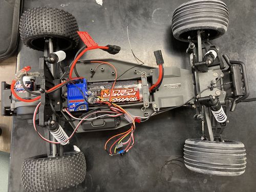
| + | On protoboard, a single SJ2-C board labeled motor was designed to control Traxxas car, in witch included DC motor for back-forward control, a servo motor for steering control, and a RPM sensor for speed control. | ||
| + | |||
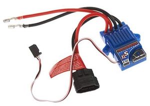
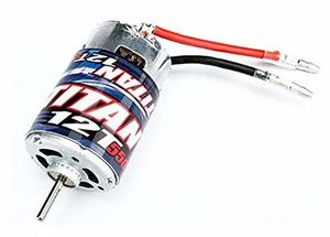
| + | Following are the key hardware component from the car. | ||
| + | <br/> | ||
| + | {| style="margin-left: auto; margin-right: auto; border: none;" | ||
| + | |[[File:ESC.jpg|center|300px|thumb|Traxxas ESC]] | ||
| + | | | ||
| + | |[[File:DCMotor.jpg|center|300px|thumb|Traxxas Brushless DC Motor]] | ||
| + | |} | ||
| + | |||
| + | ==== Servo Motor ==== | ||
| + | |||
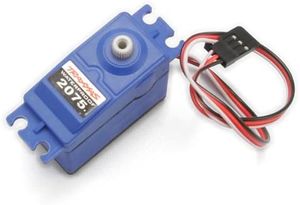
| + | We are using Traxxas 2075 for this project which came with the car and it is responsible for steering the car. It takes the 6V power directly from ESC. The servo motor is controlled directly from the SJ2 micro-controller board. The PWM signal is supplied at a frequency of 100 Hz. Based on the duty cycle of the signal sent to the servo, the direction of servo motor can be changed. | ||
| + | |||
| + | [[File:Servotrx.jpg|300px|Image: 250 pixels]] | ||
| + | |||
| + | ==== RPM Sensor ==== | ||
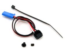
| + | The RPM sensor is used as an input to maintain a constant speed of the vehicle. The sensor we are using is Traxxas RPM sensor which using hall effect to detect the movement of the DC motor. | ||
| + | |||
| + | [[File: Rpm_sensor.jpg|300px|Image: 250 pixels]] | ||
| + | |||
| + | ==== Mounting ==== | ||
| + | [[File: RC Car2.jpg|500px|Image: 250 pixels]] | ||
=== Software Design === | === Software Design === | ||
<List the code modules that are being called periodically.> | <List the code modules that are being called periodically.> | ||
| + | |||
| + | motor.h | ||
| + | <syntaxhighlight lang="cpp"> | ||
| + | #pragma once | ||
| + | #include <stdint.h> | ||
| + | void motor__init(void); | ||
| + | // Apply brake by setting the ESC throttle to neutral | ||
| + | void brake(); | ||
| + | |||
| + | // Set the throttle to go forward | ||
| + | void go_forward(float dc_speed); | ||
| + | |||
| + | // Set the throttle to go in reverse | ||
| + | void go_reveser(); | ||
| + | |||
| + | // Set the servo motor to go straight | ||
| + | void go_straight(); | ||
| + | |||
| + | // Set the servo motor to turn left | ||
| + | void go_left(float servo_speed); | ||
| + | |||
| + | // Set the servo motor to turn right | ||
| + | void go_right(float servo_speed); | ||
| + | |||
| + | } | ||
| + | </syntaxhighlight> | ||
| + | <br> | ||
=== Technical Challenges === | === Technical Challenges === | ||
< List of problems and their detailed resolutions> | < List of problems and their detailed resolutions> | ||
| + | *'''Issue:''' RC-Car sometimes goes forward while the code commands it to backward, whereas sometimes goes backward when the code commands it to go forward. | ||
| + | *'''Reason:''' Do not initialize the RC car. | ||
| + | *''' Solution:''' Keep Neutral With remote more than 3 seconds. Otherwise, it may fail to receive the correct signals. | ||
| + | |||
| + | |||
| + | *'''Issue:''' Giving the command with sequence Forward-Neutral-backward. The car acts as Forward-stop-Forward. | ||
| + | *'''Reason:''' ignored the RC-Car protection mechanism. | ||
| + | *''' Solution:''' The command should be Forward-Neutral-Backward-Backward | ||
<HR> | <HR> | ||
<BR/> | <BR/> | ||
| + | |||
== Geographical Controller == | == Geographical Controller == | ||
| − | |||
<Picture and link to Gitlab> | <Picture and link to Gitlab> | ||
=== Hardware Design === | === Hardware Design === | ||
| + | [https://gitlab.com/rashmi_sv/the_CAN_clan/-/tree/main/projects/lpc40xx_geo/l5_application GPS Node GitLab] | ||
| + | |||
| + | *GPS | ||
| + | [[File:GPS1.jpg|150px]][[File:GPS2.jpg|150px]] | ||
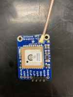
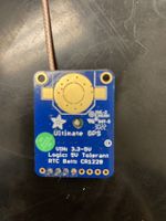
| + | *An Adafruit Ultimate GPS breakout module using the MTK3339 chipset is interfaced over UART to the Geographical controller to provide latitude and longitude updates. | ||
| + | |||
| + | *Compass | ||
| + | [[File:compass11.jpg|150px]] | ||
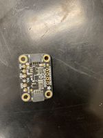
| + | *Triple-axis accelerometer/magnetometer compass module. Inside are two sensors, one is a classic 3-axis accelerometer, which can tell you which direction is down towards the Earth (by measuring gravity). The other is a magnetometer that can sense where the strongest magnetic force is coming from, generally used to detect magnetic north. | ||
=== Software Design === | === Software Design === | ||
<List the code modules that are being called periodically.> | <List the code modules that are being called periodically.> | ||
| + | The GEO controller consisted of 4 main parts which are: | ||
| + | |||
| + | *1. GPS | ||
| + | *2. Compass | ||
| + | *3. Waypoints | ||
| + | *4. Geo Algorithm | ||
| + | |||
| + | *1. GPS | ||
| + | gps.h | ||
| + | <syntaxhighlight lang="cpp"> | ||
| + | #pragma once | ||
| + | #include "stdbool.h" | ||
| + | // Note: | ||
| + | // South means negative latittude | ||
| + | // West means negative longitutde | ||
| + | typedef struct { | ||
| + | float latitude; | ||
| + | float longitude; | ||
| + | } gps_coordinates_t; | ||
| + | |||
| + | void gps__init(void); | ||
| + | void gps__get_gps_data_and_parse_coordinates(void); | ||
| + | |||
| + | gps_coordinates_t gps__get_coordinates(void); | ||
| + | bool gps__get_satellite_lock_status(void); | ||
| + | |||
| + | |||
| + | } | ||
| + | </syntaxhighlight> | ||
| + | <br> | ||
| + | |||
| + | *2. Compass | ||
| + | compass.h | ||
| + | <syntaxhighlight lang="cpp"> | ||
| + | #pragma once | ||
| + | |||
| + | #include "compass.h" | ||
| + | void compass__init(); | ||
| + | float compass__get_current_bearing(); | ||
| + | |||
| + | } | ||
| + | </syntaxhighlight> | ||
| + | <br> | ||
| + | |||
| + | *3. Waypoints | ||
| + | waypoint.h | ||
| + | <syntaxhighlight lang="cpp"> | ||
| + | #pragma once | ||
| + | |||
| + | #include "gps.h" | ||
| + | #include <stdint.h> | ||
| + | |||
| + | uint16_t waypoints__calculate_heading_to_next_point(gps_coordinates_t current_coords, gps_coordinates_t dest_coords); | ||
| + | int waypoints__calculate_distance_to_dest(gps_coordinates_t current_coords, gps_coordinates_t dest_coords); | ||
| + | |||
| + | |||
| + | } | ||
| + | </syntaxhighlight> | ||
| + | <br> | ||
| + | |||
| + | *4. Geo Algorithm | ||
| + | haversine.h | ||
| + | <syntaxhighlight lang="cpp"> | ||
| + | #pragma once | ||
| + | |||
| + | double calculate_heading(double lat1, double lon1, double lat2, double lon2); | ||
| + | double calculate_distance_in_meters(double lat1, double lon1, double lat2, double lon2); | ||
| + | |||
| + | } | ||
| + | </syntaxhighlight> | ||
| + | <br> | ||
| + | |||
| + | line-buffer.h | ||
| + | <syntaxhighlight lang="cpp"> | ||
| + | #pragma once | ||
| + | |||
| + | #include "app_queue.h" | ||
| + | #include <stdbool.h> | ||
| + | #include <stddef.h> | ||
| + | #include <stdint.h> | ||
| + | |||
| + | typedef queue_s line_buffer_s; | ||
| + | |||
| + | bool line_buffer__init(line_buffer_s *buffer, void *memory, size_t size); | ||
| + | |||
| + | bool line_buffer__add_byte(line_buffer_s *buffer, char byte); | ||
| + | |||
| + | bool line_buffer__remove_line(line_buffer_s *buffer, char *line, size_t line_max_size); | ||
| + | |||
| + | } | ||
| + | </syntaxhighlight> | ||
| + | <br> | ||
=== Technical Challenges === | === Technical Challenges === | ||
| Line 356: | Line 864: | ||
< List of problems and their detailed resolutions> | < List of problems and their detailed resolutions> | ||
| + | *'''Issue:''' Unable to get accurate coordinate from gps sensor. we will getting coordinate 30 kilometers away from correct location. | ||
| + | *'''Reason:''' Do not correct conversion in calculation. | ||
| + | *''' Solution:''' do conversion before calculation. | ||
| + | |||
| + | *'''Issue:''' In compass, we will getting values in the oppsite direction. | ||
| + | *'''Reason:''' This is the compass mechanism. | ||
| + | *''' Solution:''' subtract the compass from 360 degree | ||
<HR> | <HR> | ||
<BR/> | <BR/> | ||
| Line 361: | Line 876: | ||
<HR> | <HR> | ||
<BR/> | <BR/> | ||
| + | |||
== Communication Bridge Controller & LCD == | == Communication Bridge Controller & LCD == | ||
<Picture and link to Gitlab> | <Picture and link to Gitlab> | ||
=== Hardware Design === | === Hardware Design === | ||
| + | *LCD | ||
| + | [[File:LCD0.png|200px]][[File:LCD11.jpg|200px]] | ||
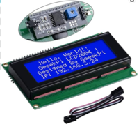
| + | *An Adafruit Ultimate GPS breakout module using the MTK3339 chipset is interfaced over UART to the Geographical controller to provide latitude and longitude updates. | ||
=== Software Design === | === Software Design === | ||
<List the code modules that are being called periodically.> | <List the code modules that are being called periodically.> | ||
| + | |||
| + | LCD_int.h | ||
| + | <syntaxhighlight lang="cpp"> | ||
| + | #pragma once | ||
| + | |||
| + | #include <stdint.h> | ||
| + | |||
| + | void init__LCD(void); | ||
| + | |||
| + | void reset__LCD(void); | ||
| + | |||
| + | void send_LCD_char(uint8_t character); | ||
| + | |||
| + | void send_LCD_string(char *input_string); | ||
| + | |||
| + | void send_LCD_command(uint8_t command); | ||
| + | |||
| + | void set_LCD_to_4_bit_mode(void); | ||
| + | |||
| + | |||
| + | } | ||
| + | </syntaxhighlight> | ||
| + | <br> | ||
| + | |||
| + | LCD_process.h | ||
| + | <syntaxhighlight lang="cpp"> | ||
| + | #pragma once | ||
| + | |||
| + | #include "project.h" | ||
| + | |||
| + | void update_sensor_for_LCD(dbc_ULTRASONIC_TO_DRIVER_s *sensor_data); | ||
| + | void update_compass_for_LCD(dbc_GEO_STATUS_s *compass_data); | ||
| + | void update_motor_for_LCD(dbc_DRIVER_TO_MOTOR_s *motor_data_s); | ||
| + | |||
| + | void LCD_display_1Hz(void); | ||
| + | // void LCD_status__display_handle_1hz(void); | ||
| + | |||
| + | } | ||
| + | </syntaxhighlight> | ||
| + | <br> | ||
=== Technical Challenges === | === Technical Challenges === | ||
| Line 373: | Line 932: | ||
< List of problems and their detailed resolutions> | < List of problems and their detailed resolutions> | ||
| + | *'''Issue:''' LCD sometime does work well. | ||
| + | *'''Reason:''' We do not provide good power supply plan. | ||
| + | *''' Solution:''' we bought another power bank and adjust the power supply plan. | ||
<HR> | <HR> | ||
<BR/> | <BR/> | ||
| + | |||
== Master Module == | == Master Module == | ||
| Line 380: | Line 943: | ||
=== Hardware Design === | === Hardware Design === | ||
| + | |||
| + | <li style="display: inline-block;">[[File:LCD12.jpg|400px|thumb|Right|LCD Display For Testing]] </li> | ||
| + | |||
| + | LCD is the most important hardware using to testing different design cases. | ||
=== Software Design === | === Software Design === | ||
| − | < | + | Streer_processor to control left, right turn function. |
| + | |||
| + | steer_processor.h | ||
| + | <syntaxhighlight lang="cpp"> | ||
| + | #pragma once | ||
| + | |||
| + | #include "project.h" | ||
| + | #include <stdint.h> | ||
| + | |||
| + | typedef enum speed_throttle_level { | ||
| + | THROTTLE_LEVEL_0 = 0, | ||
| + | THROTTLE_LEVEL_1 = 4, | ||
| + | THROTTLE_LEVEL_2 = 5, | ||
| + | THROTTLE_LEVEL_3 = 6, | ||
| + | THROTTLE_LEVEL_4 = 7, | ||
| + | } speed_throttle_level_t; | ||
| + | |||
| + | typedef enum steer_angle_level { | ||
| + | STEER_SHARP_RIGHT = -60, | ||
| + | STEER_MEDIUM_RIGHT = -50, | ||
| + | STEER_SOFT_RIGHT = -45, | ||
| + | STEER_STRAIGHT = 0, | ||
| + | STEER_SOFT_LEFT = 45, | ||
| + | STEER_MEDIUM_LEFT = 50, | ||
| + | STEER_SHARP_LEFT = 60, | ||
| + | } steer_angle_level_t; | ||
| + | |||
| + | typedef enum obstacle_threshold_level { | ||
| + | OBSTACLE_THRESHOLD_LEVEL_0 = 0, | ||
| + | OBSTACLE_THRESHOLD_LEVEL_1 = 50, // unit cm | ||
| + | OBSTACLE_THRESHOLD_LEVEL_2 = 75, // unit cm | ||
| + | OBSTACLE_THRESHOLD_LEVEL_3 = 100, // unit cm | ||
| + | NO_OBSTACLE = 150, // unit cm | ||
| + | } obstacle_threshold_level_t; | ||
| + | |||
| + | void steer_processor(dbc_DRIVER_TO_MOTOR_s *motor_val, dbc_ULTRASONIC_TO_DRIVER_s sensor_val, | ||
| + | dbc_GEO_STATUS_s geo_heading); | ||
| + | void steer_processor__obstacle_LEDs_init(); | ||
| + | |||
| + | |||
| + | |||
| + | } | ||
| + | </syntaxhighlight> | ||
| + | <br> | ||
| + | |||
| + | Controller received message then navigate to destination. | ||
| + | driver_controller.h | ||
| + | <syntaxhighlight lang="cpp"> | ||
| + | #pragma once | ||
| + | |||
| + | #include "stdbool.h" | ||
| + | |||
| + | void driver_controller__init(); | ||
| + | void driver_controller__read_all_can_messages(); | ||
| + | bool driver_controller__send_cmd_to_motor_over_can(); | ||
| + | void print_heading_and_motor_cmds(); | ||
| + | |||
| + | |||
| + | } | ||
| + | </syntaxhighlight> | ||
| + | <br> | ||
=== Technical Challenges === | === Technical Challenges === | ||
< List of problems and their detailed resolutions> | < List of problems and their detailed resolutions> | ||
| + | *'''Issue:''' difficulties with obstracl avoidance logic. | ||
| + | *'''Reason:''' complex logic to design. | ||
| + | *''' Solution:''' implementation different test cases and adjust the algorithm according to the results from actually test. | ||
<HR> | <HR> | ||
<BR/> | <BR/> | ||
| + | |||
== Mobile Application == | == Mobile Application == | ||
<Picture and link to Gitlab> | <Picture and link to Gitlab> | ||
| − | === | + | === APP Interface === |
| + | <li style="display: inline-block;">[[File:APP Interface1.jpg|200px|thumb|Right|App Interface]] </li> | ||
| + | <li style="display: inline-block;">[[File:APP Interface2.jpg|200px|thumb|Right|App Interface]] </li> | ||
| + | <li style="display: inline-block;">[[File:APP Interface3.jpg|200px|thumb|Right|App Interface]] </li> | ||
| + | <li style="display: inline-block;">[[File:APP Interface4.jpg|200px|thumb|Right|Parameter]] </li> | ||
| + | <li style="display: inline-block;">[[File:APP Interface5.jpg|200px|thumb|Right|App Interface]] </li> | ||
=== Software Design === | === Software Design === | ||
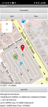
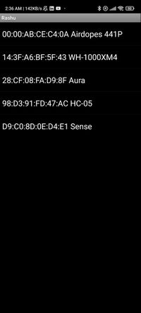
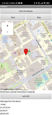
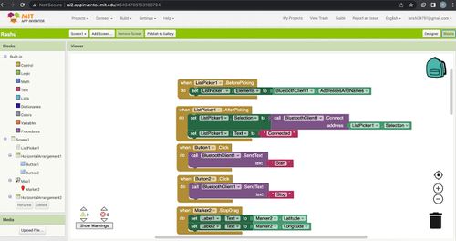
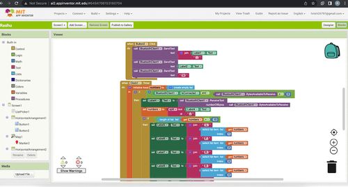
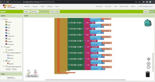
| − | + | The map block is used to create and display a 2D map of the world for location, navigation and other map functions. It uses an open-source map library which is very similar to Google Maps. The Map bloc has several functions including display, zoom, direction, distance, coordinate calculation. Fireblot uses this block to locate a destination location for the car and send the corresponding latitude and longitude values. This is made possible by the marker block. Markers can be placed on any location on the map and the pinpointed location coordinates can be received as floating point integers. These values are displayed on the app and also used to send as a bluetooth message to the HC-05 module when required. | |
| + | |||
| + | <li style="display: inline-block;">[[File:APP Programming1.jpg|500px|thumb|Right|App Programming1]] </li> | ||
| + | <li style="display: inline-block;">[[File:APP Programming2.jpg|500px|thumb|Right|App Programming2]] </li> | ||
| + | <li style="display: inline-block;">[[File:APP Programming3.jpg|500px|thumb|Right|App Programming3]] </li> | ||
=== Technical Challenges === | === Technical Challenges === | ||
< List of problems and their detailed resolutions> | < List of problems and their detailed resolutions> | ||
| + | |||
| + | *'''Issue:''' Don't know how to start. | ||
| + | *'''Reason:''' not familiar with mobile app | ||
| + | *''' Solution:''' learn from some video . | ||
| Line 407: | Line 1,051: | ||
<HR> | <HR> | ||
<BR/> | <BR/> | ||
| + | |||
== Conclusion == | == Conclusion == | ||
| − | + | Generally speaking ,this is a successful project for team CAN CLAN. We achieved all required functions, and bonus reverse function for the RC car. However, the process is not that easy. We were even still testing and debugging at the night before demo day. | |
<What did you learn?> | <What did you learn?> | ||
| + | |||
| + | There are many problems we faced and learn to solve through the project: | ||
| + | * Hardware solution | ||
| + | We need to find a clear and easy solution to mount all components on the car. We were considered to order PCB board online. However, none of us used the PCB designers' software before. Since time limited, we switch to plan b, to mount on protoboard. | ||
| + | To avoid connection fault, we need to draw the connection mechanism and soldering carefully. We also meet the wight balance issue, which makes RC car always go right. In order to solve that, we changed to use long stand off and put power bank in the mid. | ||
| + | |||
| + | * Test and debugging | ||
| + | we spend the most time on debugging. Tested each component again and again when is not working coordinately. To troubleshoot driving logic issue, we set many cases, test one by one, read the date from LCD, and adjust our code accordingly. | ||
=== Project Video === | === Project Video === | ||
| + | https://www.youtube.com/watch?v=kvuTwDW_AXE | ||
| + | |||
| + | https://youtube.com/shorts/Oli5RZc1EBU?feature=share | ||
=== Project Source Code === | === Project Source Code === | ||
| + | https://https://gitlab.com/rashmi_sv/the_CAN_clan | ||
=== Advise for Future Students === | === Advise for Future Students === | ||
| − | + | * Teamwork is the most important key skills in this project. | |
| + | ** Plan your teamwork well. Meet to discuss tasks for the week, working individually, meet own weekend and debugging together. | ||
| + | ** Assign task to suitable person. | ||
| + | * Read the wiki pages from previous groups as early as possible | ||
| + | ** It will give you the key idea of the what the project about | ||
| + | ** You are actually study how to code during the lab HW | ||
| + | ** You may meet the same challenge they are facing | ||
=== Acknowledgement === | === Acknowledgement === | ||
| + | Don't hesitate to communication, talk to Preet, talk to TA, talk to other team. It will help you more clear about your own ideas, and may open a new direction solving problems. | ||
=== References === | === References === | ||
| + | *[https://https://www.amazon.com/dp/B00A7YGVJI?psc=1&ref=ppx_pop_dt_b_product_details LV-MaxSonar-EZ1 Ultrasonic Range Finder ] | ||
| + | *[https://www.movable-type.co.uk/scripts/latlong.html Bearing and Distance computation formulas ] | ||
| + | *[https://learn.adafruit.com/introducing-the-adafruit-bluefruit-le-uart-friend Bluetooth Tutorial] | ||
| + | *[https://www.mouser.com/datasheet/2/389/lsm303agr-954987.pdf Compass datasheet] | ||
| + | *[https://learn.adafruit.com/adafruit-ultimate-gps/overview GPS tutorial] | ||
| + | *[https://www.youtube.com/watch?v=cGI8mrIanpk&ab_channel=DigiKey Compass calibration tutorial] | ||
| + | *[https://sites.google.com/view/sailboatinstruments1 Compass calibration tool] | ||
Latest revision as of 01:07, 2 June 2023
Contents
CAN CLAN
Picture of the RC Car
Abstract
Our goal for this project is to use knowledge we gathered from lectures to design, implement, and test a self-driving RC car using a Controller Area Network (CAN) bus for controller communication. The project involves FreeRTOS and utilizes periodic tasks (running at 1Hz, 10Hz, and 100Hz) to gather, process, and display data from various embedded modules.
Introduction
The project was divided into 5 modules:
- Sensor Information
- Motor Operation
- Geological Information
- Driver & LCD Manager
- Bridge & Android Application
Team Members & Responsibilities
Gitlab Project Link - https://gitlab.com/rashmi_sv/the_CAN_clan.git
- Driver Controller
- Motor Controller
- Geo Controller
- GPS Interfacing
- Mobile App
- Integration Testing
Zeel Jatinkumar Lia
- Sensor and Bridge Controller
- Ultrasonic sensors
- LCD interfacing
- Integration Testing
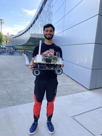
Priyam Hajisheth
- Hardware mounting
- Mobile App
- Integration Testing
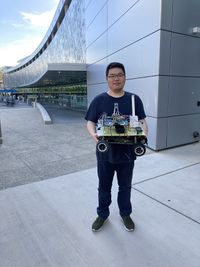
Xinyu He
- Hardware solution
- Wiki Page Update
- Integration Testing
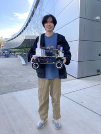
Hongjin Cheng
- Protoboard soldering and Hardware assembling
- Compass, RPM Sensor, DC and servo motor interfacing
- Integration Testing
Schedule
| Week# | Start Date | End Date | Task | Status |
|---|---|---|---|---|
| 1 | 03/01/2023 | 03/07/2023 |
|
|
| 2 | 03/08/2023 | 03/14/2023 |
|
|
| 3 | 03/15/2023 | 03/21/2023 |
|
|
| 4 | 03/22/2023 | 03/28/2023 |
|
|
| 5 | 03/29/2023 | 04/04/2023 |
|
|
| 6 | 04/05/2023 | 04/11/2023 |
|
|
| 7 | 04/12/2022 | 04/18/2022 |
|
|
| 8 | 04/19/2023 | 04/25/2023 |
|
|
| 9 | 04/26/2023 | 05/02/2023 |
|
|
| 10 | 05/03/2023 | 05/09/2023 |
|
|
| 11 | 05/10/2023 | 05/16/2023 |
|
|
| 11 | 05/23/2023 | 05/23/2023 |
|
|
Parts List & Cost
| Item# | Part Desciption | Vendor | Qty | Cost |
|---|---|---|---|---|
| 1 | RC Car | Traxxas [1] | 1 | $251.51 |
| 2 | CAN Transceivers | Amazon [2] | 4 | $43.72 |
| 3 | SJ-2 Board | 4 | $200.00 | |
| 4 | LV-MaxSonar-EZ1 Ultrasonic Range Finder | Amazon [3] | 4 | $131.20 |
| 5 | GPS | Amazon [4] | 1 | $10.99 |
| 6 | RPM Sensor | Amazon [5] | 1 | $16.76 |
| 7 | Buletooth | Amazon[6] | 1 | $15.99 |
| 8 | LCD Display | Amazon [7] | 1 | $10.99 |
| 9 | Battery/Charger | 1 | $62.95 | |
| 10 | Cable | Amazon [8] | 1 | $7.99 |
| 11 | LSM303AGR Compass | Adafruit [9] | 1 | $19.57 |
| 12 | Magnet holder | 1 | $8.09 | |
| 13 | 2*20 header | 1 | $7.59 | |
| 14 | RPM holder | 1 | $7.73 | |
| 15 | long stand off | 1 | $2.21 | |
| 16 | Mount board | 1 | None | |
| 17 | Protoboard | 1 | None | |
| 18 | Small stand off | None | ||
| 19 | Pin header | None | ||
| 20 | Switch for DC motor | 1 | None | |
| 21 | wire connectors | 1 | None |
Printed Circuit Board
The Following table indicate the pin connection of all Hardware .
This is the pictures show protoboard and the mount board.
CAN Communication
<Talk about your message IDs or communication strategy, such as periodic transmission, MIA management etc.> We are using 100HZ for CAN bus communication, 50HZ for sensors, 10HZ for calculation, 1HZ for printing. The following table shows the Message ID.
| Node | Message ID | |
|---|---|---|
| 1 | ULTRASONIC_TO_DRIVER | 100 |
| 2 | GPS_DESTINATION | 300 |
| 3 | DRIVE_STATUS_CMD | 50 |
| 4 | SELF_TEST_CMD | 600 |
| 5 | DRIVER_TO_MOTOR | 200 |
| 6 | DRIVER_SELF_TEST_RESULT | 610 |
| 7 | GEO_STATUS | 400 |
| 8 | GEO_SELF_TEST_RESULT | 620 |
| 9 | GEO_CURRENT_COORDS | 650 |
| 10 | MOTOR_TO_APP_DBG | 500 |
Hardware Design
<Show your CAN bus hardware design>
- The following is the CAN Transceiver Design logicwork.
DBC File
Gitlab link to our DBC file : https://gitlab.com/rashmi_sv/the_CAN_clan/-/blob/dev/dbc_file/dbc/project.dbc
<You can optionally use an inline image>
VERSION ""

NS_ :
        BA_
        BA_DEF_
        BA_DEF_DEF_
        BA_DEF_DEF_REL_
        BA_DEF_REL_
        BA_DEF_SGTYPE_
        BA_REL_
        BA_SGTYPE_
        BO_TX_BU_
        BU_BO_REL_
        BU_EV_REL_
        BU_SG_REL_
        CAT_
        CAT_DEF_
        CM_
        ENVVAR_DATA_
        EV_DATA_
        FILTER
        NS_DESC_
        SGTYPE_
        SGTYPE_VAL_
        SG_MUL_VAL_
        SIGTYPE_VALTYPE_
        SIG_GROUP_
        SIG_TYPE_REF_
        SIG_VALTYPE_
        VAL_
        VAL_TABLE_

BS_:

BU_: DBG DRIVER GEO MOTOR SENSOR_BRIDGE


BO_ 100 ULTRASONIC_TO_DRIVER: 5 SENSOR_BRIDGE
 SG_ ULTRASONIC_TO_DRIVER_left : 0|10@1+ (1,0) [0|511] "cm" DRIVER
 SG_ ULTRASONIC_TO_DRIVER_right : 10|10@1+ (1,0) [0|511] "cm" DRIVER
 SG_ ULTRASONIC_TO_DRIVER_front : 20|10@1+ (1,0) [0|511] "cm" DRIVER
 SG_ ULTRASONIC_TO_DRIVER_back : 30|10@1+ (1,0) [0|511] "cm" DRIVER

BO_ 300 GPS_DESTINATION: 8 SENSOR_BRIDGE
 SG_ GPS_DEST_LATITUDE_SCALED_100000 : 0|32@1- (1,0) [0|0] "Degrees" GEO
 SG_ GPS_DEST_LONGITUDE_SCALED_100000 : 32|32@1- (1,0) [0|0] "Degrees" GEO

BO_ 50 DRIVE_STATUS_CMD: 1 SENSOR_BRIDGE
 SG_ DRIVE_STATUS_CMD_start : 0|1@1+ (1,0) [0|0] "" MOTOR

BO_ 600 SELF_TEST_CMD: 1 SENSOR_BRIDGE
 SG_ SELF_TEST_CMD_start : 0|1@1+ (1,0) [0|0] "" MOTOR, GEO, DRIVER


BO_ 200 DRIVER_TO_MOTOR: 2 DRIVER
 SG_ DRIVER_TO_MOTOR_steer : 0|8@1- (1,0) [0|0] "degrees" MOTOR, SENSOR_BRIDGE
 SG_ DRIVER_TO_MOTOR_speed : 8|8@1- (1,0) [0|50] "mph" MOTOR, SENSOR_BRIDGE

BO_ 610 DRIVER_SELF_TEST_RESULT: 1 DRIVER
 SG_ DRIVER_SELF_TEST_RESULT_status : 0|8@1+ (1,0) [0|0] "" SENSOR_BRIDGE


BO_ 400 GEO_STATUS: 8 GEO
  SG_ GEO_STATUS_COMPASS_HEADING : 0|12@1+ (1,0) [0|359] "Degrees" DRIVER, SENSOR_BRIDGE
  SG_ GEO_STATUS_COMPASS_BEARING : 12|12@1+ (1,0) [0|359] "Degrees" DRIVER, SENSOR_BRIDGE
  SG_ GEO_STATUS_DISTANCE_TO_DESTINATION : 24|16@1+ (0.1,0) [0|0] "Meters" DRIVER, SENSOR_BRIDGE
  SG_ GEO_STATUS_SATELLITE_LOCKED : 40|1@1+ (1,0) [0|0] "" DRIVER, SENSOR_BRIDGE

BO_ 620 GEO_SELF_TEST_RESULT: 1 GEO
 SG_ GEO_SELF_TEST_RESULT_status : 0|8@1+ (1,0) [0|0] "" SENSOR_BRIDGE

BO_ 650 GEO_CURRENT_COORDS: 8 SENSOR_BRIDGE
 SG_ CURR_LATITUDE_SCALED_100000 : 0|32@1- (1,0) [0|0] "Degrees" SENSOR_BRIDGE
 SG_ CURR_LONGITUDE_SCALED_100000 : 32|32@1- (1,0) [0|0] "Degrees" SENSOR_BRIDGE


BO_ 500 MOTOR_TO_APP_DBG: 2 MOTOR
 SG_ MOTOR_TO_APP_DBG_current_steer : 0|8@1- (1,0) [0|0] "degrees" SENSOR_BRIDGE
 SG_ MOTOR_TO_APP_DBG_current_speed : 8|8@1- (1,0) [0|50] "mph" SENSOR_BRIDGE

BO_ 620 MOTOR_SELF_TEST_RESULT: 1 MOTOR
 SG_ MOTOR_SELF_TEST_RESULT_status : 0|8@1+ (1,0) [0|0] "" SENSOR_BRIDGE


CM_ BU_ DRIVER "The LED display and driver controller driving the car";
CM_ BU_ MOTOR "The RPM sensor, DC and servo motor controller of the car";
CM_ BU_ SENSOR_BRIDGE "The Bluetooth and the sonar sensor controller of the car";
CM_ BU_ GEO "The GPS and compass sensor controller of the car";

BA_DEF_ "BusType" STRING ;
BA_DEF_ BO_ "GenMsgCycleTime" INT 0 0;
BA_DEF_ SG_ "FieldType" STRING ;

BA_DEF_DEF_ "BusType" "CAN";
BA_DEF_DEF_ "FieldType" "";
BA_DEF_DEF_ "GenMsgCycleTime" 0;

BA_ "GenMsgCycleTime" BO_ 100 1000;
BA_ "GenMsgCycleTime" BO_ 200 50;
Sensor ECU
<Picture and link to Gitlab> Sensor Node GitLab
Hardware Design
LV-MaxSonar-EZ1 Ultrasonic Range Finder
- MaxSonar-EZ1 detects objects from 0" to 254".
- 2.5-5.5V operation range. Low 2mA supply current.
- 42kHz Ultrasonic sensor with 20Hz reading rate.
- Incredibly Small Package Sonar Range Finder.
- Serial Output, PWM output, Analog Output.
Sensor Design
- We used 4 sensors-LV-MaxSonar-EZ1 Ultrasonic Range Finder. These ultrasonic sensors are used by the RC car for the purpose of obstacle avoidance. Three sensors were placed on the front side of the RC car and one on the back. They use I2C communication to send distance data to the SJ2 microcontroller. On the SJ2 microcontroller, P0.10 was used for SDA, and P0.11 was used for SCL. It takes in +5V supply voltage. A LED is soldering on sensors to indicate if the sensor is working well.
Software Design
<List the code modules that are being called periodically.>
- Sensors are divided into two groups:
- 1. Front-rear group
- 2. Left-right group
Each group use 50HZ. The following code shows how it being called periodically.
void periodic_callbacks__100Hz(uint32_t callback_count) {
  CAN_RX_MSGS_FOR_BRIDGE();
  Sensor_Controller__100hz_handler(callback_count);
  can_ultrasonic_sensor_transmit_messages();
}
The following is the code for sensor controller.
#include "LV_sensor_controller.h"
#include "LV_sensor_pin_init.h"

static dbc_ULTRASONIC_TO_DRIVER_s ultra_sonic_data;

static gpio_s FRONT_OBSTACLE_LED;
static gpio_s LEFT_OBSTACLE_LED;
static gpio_s RIGHT_OBSTACLE_LED;
static gpio_s BACK_OBSTACLE_LED;

void Sensor_Controller_init(void) {
  FRONT_OBSTACLE_LED = gpio__construct_as_output(GPIO__PORT_2, 2);
  LEFT_OBSTACLE_LED = gpio__construct_as_output(GPIO__PORT_2, 0);
  RIGHT_OBSTACLE_LED = gpio__construct_as_output(GPIO__PORT_2, 1);
  BACK_OBSTACLE_LED = gpio__construct_as_output(GPIO__PORT_2, 4);
  adc_init_for_LV_sensors();
  trigger_pins_for_LV_sensors();
}

void Sensor_Controller__print_sensor_values() {
  printf("L:%d F:%d R:%d B:%d\n", ultra_sonic_data.ULTRASONIC_TO_DRIVER_left,
         ultra_sonic_data.ULTRASONIC_TO_DRIVER_front, ultra_sonic_data.ULTRASONIC_TO_DRIVER_right,
         ultra_sonic_data.ULTRASONIC_TO_DRIVER_back);
}

static void update_obstacle_LED(int sensor_value, gpio_s obstacle_led) {
  if (sensor_value > 100) { // no obstacle detected. Turn OFF LED
    gpio__reset(obstacle_led);
  } else {
    gpio__set(obstacle_led); // obstacle detected. Turn ON LED
  }
}

void Sensor_Controller__100hz_handler(uint32_t callback_count) {
  if (callback_count % 2 == 0) {
    collect_left_LV_sensor_values_buffer();
    ultra_sonic_data.ULTRASONIC_TO_DRIVER_left = sort_sensor_buffer_data_and_get_median(LEFT_ULTRA_SONIC);
    update_obstacle_LED(ultra_sonic_data.ULTRASONIC_TO_DRIVER_left, LEFT_OBSTACLE_LED);

    collect_right_LV_sensor_values_buffer();
    ultra_sonic_data.ULTRASONIC_TO_DRIVER_right = sort_sensor_buffer_data_and_get_median(RIGHT_ULTRA_SONIC);
    update_obstacle_LED(ultra_sonic_data.ULTRASONIC_TO_DRIVER_right, RIGHT_OBSTACLE_LED);
  }

  else {

    collect_back_LV_sensor_values_buffer();
    ultra_sonic_data.ULTRASONIC_TO_DRIVER_back = sort_sensor_buffer_data_and_get_median(BACK_ULTRA_SONIC);
    update_obstacle_LED(ultra_sonic_data.ULTRASONIC_TO_DRIVER_back, BACK_OBSTACLE_LED);

    collect_front_LV_sensor_values_buffer();
    ultra_sonic_data.ULTRASONIC_TO_DRIVER_front = sort_sensor_buffer_data_and_get_median(FRONT_ULTRA_SONIC);
    update_obstacle_LED(ultra_sonic_data.ULTRASONIC_TO_DRIVER_front, FRONT_OBSTACLE_LED);
  }
}
dbc_ULTRASONIC_TO_DRIVER_s get_ultra_sonic_data(void) { return ultra_sonic_data; }
Technical Challenges
< List of problems and their detailed resolutions>
- Issue: Sensors test well independently, but not sensitive when mount on RC car .
- Reason: Sensor do not have enough power supply.
- Solution: 1.check connecting and solder in protoboard.
- 2.Re-design the power supply plan.
- Issue: While using two brand sensors, Front sensor works well, but left/right sensor working randomly. For sensors couldn’t work well at the same time.
- Reason: We config the sensor in two groups, and it causes the sensors to crosstalk.
- Solution: 1. Only use one brand.
- 2.Turning on only two sensors at a time.(left + right then front +rear).
- Issue: Rear Sensor doesn't work well with bad mounting.
- Reason: the sensors are mounted heading to LCD.
- Solution: we use higher stand off of read sensor.
Motor ECU
Hardware Design
On protoboard, a single SJ2-C board labeled motor was designed to control Traxxas car, in witch included DC motor for back-forward control, a servo motor for steering control, and a RPM sensor for speed control.
Following are the key hardware component from the car.
Servo Motor
We are using Traxxas 2075 for this project which came with the car and it is responsible for steering the car. It takes the 6V power directly from ESC. The servo motor is controlled directly from the SJ2 micro-controller board. The PWM signal is supplied at a frequency of 100 Hz. Based on the duty cycle of the signal sent to the servo, the direction of servo motor can be changed.
RPM Sensor
The RPM sensor is used as an input to maintain a constant speed of the vehicle. The sensor we are using is Traxxas RPM sensor which using hall effect to detect the movement of the DC motor.
Mounting
Software Design
<List the code modules that are being called periodically.>
motor.h
#pragma once
#include <stdint.h>
void motor__init(void);
// Apply brake by setting the ESC throttle to neutral
void brake();

// Set the throttle to go forward
void go_forward(float dc_speed);

// Set the throttle to go in reverse
void go_reveser();

// Set the servo motor to go straight
void go_straight();

// Set the servo motor to turn left
void go_left(float servo_speed);

// Set the servo motor to turn right
void go_right(float servo_speed);

}
Technical Challenges
< List of problems and their detailed resolutions>
- Issue: RC-Car sometimes goes forward while the code commands it to backward, whereas sometimes goes backward when the code commands it to go forward.
- Reason: Do not initialize the RC car.
- Solution: Keep Neutral With remote more than 3 seconds. Otherwise, it may fail to receive the correct signals.
- Issue: Giving the command with sequence Forward-Neutral-backward. The car acts as Forward-stop-Forward.
- Reason: ignored the RC-Car protection mechanism.
- Solution: The command should be Forward-Neutral-Backward-Backward
Geographical Controller
<Picture and link to Gitlab>
Hardware Design
- GPS
- An Adafruit Ultimate GPS breakout module using the MTK3339 chipset is interfaced over UART to the Geographical controller to provide latitude and longitude updates.
- Compass
- Triple-axis accelerometer/magnetometer compass module. Inside are two sensors, one is a classic 3-axis accelerometer, which can tell you which direction is down towards the Earth (by measuring gravity). The other is a magnetometer that can sense where the strongest magnetic force is coming from, generally used to detect magnetic north.
Software Design
<List the code modules that are being called periodically.> The GEO controller consisted of 4 main parts which are:
- 1. GPS
- 2. Compass
- 3. Waypoints
- 4. Geo Algorithm
- 1. GPS
gps.h
#pragma once
#include "stdbool.h"
// Note:
// South means negative latittude
// West means negative longitutde
typedef struct {
  float latitude;
  float longitude;
} gps_coordinates_t;

void gps__init(void);
void gps__get_gps_data_and_parse_coordinates(void);

gps_coordinates_t gps__get_coordinates(void);
bool gps__get_satellite_lock_status(void);


}
- 2. Compass
compass.h
#pragma once

#include "compass.h"
void compass__init();
float compass__get_current_bearing();

}
- 3. Waypoints
waypoint.h
#pragma once

#include "gps.h"
#include <stdint.h>

uint16_t waypoints__calculate_heading_to_next_point(gps_coordinates_t current_coords, gps_coordinates_t dest_coords);
int waypoints__calculate_distance_to_dest(gps_coordinates_t current_coords, gps_coordinates_t dest_coords);


}
- 4. Geo Algorithm
haversine.h
#pragma once

double calculate_heading(double lat1, double lon1, double lat2, double lon2);
double calculate_distance_in_meters(double lat1, double lon1, double lat2, double lon2);

}
line-buffer.h
#pragma once

#include "app_queue.h"
#include <stdbool.h>
#include <stddef.h>
#include <stdint.h>

typedef queue_s line_buffer_s;

bool line_buffer__init(line_buffer_s *buffer, void *memory, size_t size);

bool line_buffer__add_byte(line_buffer_s *buffer, char byte);

bool line_buffer__remove_line(line_buffer_s *buffer, char *line, size_t line_max_size);

}
Technical Challenges
< List of problems and their detailed resolutions>
- Issue: Unable to get accurate coordinate from gps sensor. we will getting coordinate 30 kilometers away from correct location.
- Reason: Do not correct conversion in calculation.
- Solution: do conversion before calculation.
- Issue: In compass, we will getting values in the oppsite direction.
- Reason: This is the compass mechanism.
- Solution: subtract the compass from 360 degree
Communication Bridge Controller & LCD
<Picture and link to Gitlab>
Hardware Design
- LCD
- An Adafruit Ultimate GPS breakout module using the MTK3339 chipset is interfaced over UART to the Geographical controller to provide latitude and longitude updates.
Software Design
<List the code modules that are being called periodically.>
LCD_int.h
#pragma once

#include <stdint.h>

void init__LCD(void);

void reset__LCD(void);

void send_LCD_char(uint8_t character);

void send_LCD_string(char *input_string);

void send_LCD_command(uint8_t command);

void set_LCD_to_4_bit_mode(void);


}
LCD_process.h
#pragma once

#include "project.h"

void update_sensor_for_LCD(dbc_ULTRASONIC_TO_DRIVER_s *sensor_data);
void update_compass_for_LCD(dbc_GEO_STATUS_s *compass_data);
void update_motor_for_LCD(dbc_DRIVER_TO_MOTOR_s *motor_data_s);

void LCD_display_1Hz(void);
// void LCD_status__display_handle_1hz(void);

}
Technical Challenges
< List of problems and their detailed resolutions>
- Issue: LCD sometime does work well.
- Reason: We do not provide good power supply plan.
- Solution: we bought another power bank and adjust the power supply plan.
Master Module
<Picture and link to Gitlab>
Hardware Design
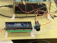
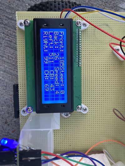
LCD is the most important hardware using to testing different design cases.
Software Design
Streer_processor to control left, right turn function.
steer_processor.h
#pragma once

#include "project.h"
#include <stdint.h>

typedef enum speed_throttle_level {
  THROTTLE_LEVEL_0 = 0,
  THROTTLE_LEVEL_1 = 4,
  THROTTLE_LEVEL_2 = 5,
  THROTTLE_LEVEL_3 = 6,
  THROTTLE_LEVEL_4 = 7,
} speed_throttle_level_t;

typedef enum steer_angle_level {
  STEER_SHARP_RIGHT = -60,
  STEER_MEDIUM_RIGHT = -50,
  STEER_SOFT_RIGHT = -45,
  STEER_STRAIGHT = 0,
  STEER_SOFT_LEFT = 45,
  STEER_MEDIUM_LEFT = 50,
  STEER_SHARP_LEFT = 60,
} steer_angle_level_t;

typedef enum obstacle_threshold_level {
  OBSTACLE_THRESHOLD_LEVEL_0 = 0,
  OBSTACLE_THRESHOLD_LEVEL_1 = 50,  // unit cm
  OBSTACLE_THRESHOLD_LEVEL_2 = 75,  // unit cm
  OBSTACLE_THRESHOLD_LEVEL_3 = 100, // unit cm
  NO_OBSTACLE = 150,                // unit cm
} obstacle_threshold_level_t;

void steer_processor(dbc_DRIVER_TO_MOTOR_s *motor_val, dbc_ULTRASONIC_TO_DRIVER_s sensor_val,
                     dbc_GEO_STATUS_s geo_heading);
void steer_processor__obstacle_LEDs_init();


}
Controller received message then navigate to destination. driver_controller.h
#pragma once

#include "stdbool.h"

void driver_controller__init();
void driver_controller__read_all_can_messages();
bool driver_controller__send_cmd_to_motor_over_can();
void print_heading_and_motor_cmds();


}
Technical Challenges
< List of problems and their detailed resolutions>
- Issue: difficulties with obstracl avoidance logic.
- Reason: complex logic to design.
- Solution: implementation different test cases and adjust the algorithm according to the results from actually test.
Mobile Application
<Picture and link to Gitlab>
APP Interface
Software Design
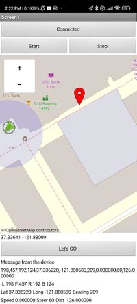
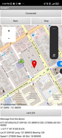
The map block is used to create and display a 2D map of the world for location, navigation and other map functions. It uses an open-source map library which is very similar to Google Maps. The Map bloc has several functions including display, zoom, direction, distance, coordinate calculation. Fireblot uses this block to locate a destination location for the car and send the corresponding latitude and longitude values. This is made possible by the marker block. Markers can be placed on any location on the map and the pinpointed location coordinates can be received as floating point integers. These values are displayed on the app and also used to send as a bluetooth message to the HC-05 module when required.
Technical Challenges
< List of problems and their detailed resolutions>
- Issue: Don't know how to start.
- Reason: not familiar with mobile app
- Solution: learn from some video .
Conclusion
Generally speaking ,this is a successful project for team CAN CLAN. We achieved all required functions, and bonus reverse function for the RC car. However, the process is not that easy. We were even still testing and debugging at the night before demo day.
<What did you learn?>
There are many problems we faced and learn to solve through the project:
- Hardware solution
We need to find a clear and easy solution to mount all components on the car. We were considered to order PCB board online. However, none of us used the PCB designers' software before. Since time limited, we switch to plan b, to mount on protoboard. To avoid connection fault, we need to draw the connection mechanism and soldering carefully. We also meet the wight balance issue, which makes RC car always go right. In order to solve that, we changed to use long stand off and put power bank in the mid.
- Test and debugging
we spend the most time on debugging. Tested each component again and again when is not working coordinately. To troubleshoot driving logic issue, we set many cases, test one by one, read the date from LCD, and adjust our code accordingly.
Project Video
https://www.youtube.com/watch?v=kvuTwDW_AXE
https://youtube.com/shorts/Oli5RZc1EBU?feature=share
Project Source Code
https://https://gitlab.com/rashmi_sv/the_CAN_clan
Advise for Future Students
- Teamwork is the most important key skills in this project.
- Plan your teamwork well. Meet to discuss tasks for the week, working individually, meet own weekend and debugging together.
- Assign task to suitable person.
- Read the wiki pages from previous groups as early as possible
- It will give you the key idea of the what the project about
- You are actually study how to code during the lab HW
- You may meet the same challenge they are facing
Acknowledgement
Don't hesitate to communication, talk to Preet, talk to TA, talk to other team. It will help you more clear about your own ideas, and may open a new direction solving problems.
References
- LV-MaxSonar-EZ1 Ultrasonic Range Finder
- Bearing and Distance computation formulas
- Bluetooth Tutorial
- Compass datasheet
- GPS tutorial
- Compass calibration tutorial
- Compass calibration tool
