Difference between revisions of "F22: Thunder Flash"
(→Game Logic) |
(→Team Members & Technical Responsibilities) |
||
| (49 intermediate revisions by the same user not shown) | |||
| Line 1: | Line 1: | ||
| − | + | [[File:Top image.png|right|500px|thumb|Traditional Bow and Arrow Game on Windows]] | |
| − | + | ||
| − | |||
| − | |||
| − | |||
| − | |||
| − | |||
| − | |||
| − | |||
| − | |||
| − | |||
== '''Bow and Arrow''' == | == '''Bow and Arrow''' == | ||
| + | |||
| + | [[File:Bow&Arrow Game.png|center|800px|thumb|]] | ||
== '''Abstract''' == | == '''Abstract''' == | ||
| − | Bow and arrow is a fun, aiming archery game. | + | Bow and arrow is a fun, aiming archery game. Our goal was to create a similar version to the 1992 arcade game 'Bow and Arrow,' in which the player takes on the role of a skilled bowman on a quest to fight the dreaded Black Archer. There are two levels in our game. The challenges increase as the level advances. The player shoots the arrow at the balloons with a joystick. Before the arrows run out, the player must acquire a WIN SCORE. There are also rocks and three lives on the second level. When the player hits the rock, he loses one life. An LED matrix displays the entire game. In addition to visuals, the game has sound effects achieved using MP3. There is no timer in this score-based game. |
| + | '''Enjoy the Game!''' | ||
== '''Objectives & Introduction''' == | == '''Objectives & Introduction''' == | ||
| Line 21: | Line 15: | ||
Other objectives are the following: | Other objectives are the following: | ||
| − | |||
* Use the FreeRTOS Real-Time Operating System on both SJ2 boards. | * Use the FreeRTOS Real-Time Operating System on both SJ2 boards. | ||
* Establish UART communications through Xbee between the two SJ-Two Microcontrollers. | * Establish UART communications through Xbee between the two SJ-Two Microcontrollers. | ||
* Create simple coding logic for displaying required characters and game objects. | * Create simple coding logic for displaying required characters and game objects. | ||
* Add background music to the game to enhance the gameplay experience. | * Add background music to the game to enhance the gameplay experience. | ||
| + | * Design custom PCBs for both the gamepad and matrix controller SJ2 boards. | ||
| + | |||
| + | |||
| + | |||
| + | '''HOW TO PLAY BOW AND ARROW:''' | ||
| + | |||
| + | The main aim of the game is to burst all the balloons and advance to the next level. | ||
| + | |||
| + | * Using the joystick on the game controller, move the bow up or down. | ||
| + | * Shoot arrows by pressing the joystick to burst the balloons. | ||
| + | |||
| + | '''''Level 1''''' | ||
| + | * Achieve a target score of 45 with the 10 provided arrows. | ||
| + | * If not game is over and the player can restart the level. | ||
| + | * If the level is won, press o start level 2. | ||
| + | |||
| + | '''''Level 2''''' | ||
| + | * Avoid hitting the rocks to not lose your life. | ||
| + | * Achieve a target score of 45 with the 10 provided arrows. | ||
| + | * If not, the game is over and the player goes back to level1. | ||
== '''Team Members & Technical Responsibilities''' == | == '''Team Members & Technical Responsibilities''' == | ||
| − | + | [[File: CmpE244_F22_T6_Group_Pic.jpeg|right|400px|thumb|]] | |
*'''''[https://www.linkedin.com/in/-shreya-kulkarni/ Shreya Kulkarni]''''' | *'''''[https://www.linkedin.com/in/-shreya-kulkarni/ Shreya Kulkarni]''''' | ||
| − | ** <font color="BLACK"> | + | ** <font color="BLACK">Implementation and Integration of Graphics Driver</font> |
| − | ** <font color="BLACK">Game logic design</font> | + | ** <font color="BLACK">Game logic design and Implementation</font> |
| − | ** <font color="BLACK">Joystick | + | ** <font color="BLACK">Joystick Integration</font> |
*'''''[https://www.linkedin.com/in/pinky-mathew96/ Pinky Mathew]''''' | *'''''[https://www.linkedin.com/in/pinky-mathew96/ Pinky Mathew]''''' | ||
| Line 42: | Line 55: | ||
*'''''[https://www.linkedin.com/in/pushkar-deodhar/ Pushkar Deodhar]''''' | *'''''[https://www.linkedin.com/in/pushkar-deodhar/ Pushkar Deodhar]''''' | ||
| − | ** <font color="BLACK">Zigbee module</font> | + | ** <font color="BLACK">Zigbee module and Joystick Driver design</font> |
** <font color="BLACK">Integrating MP3 module with the Game</font> | ** <font color="BLACK">Integrating MP3 module with the Game</font> | ||
** <font color="BLACK">Hardware Designing & PCB Integration</font> | ** <font color="BLACK">Hardware Designing & PCB Integration</font> | ||
*'''''[https://www.linkedin.com/in/noelsmithd/ Noel Smith]''''' | *'''''[https://www.linkedin.com/in/noelsmithd/ Noel Smith]''''' | ||
| − | ** <font color="BLACK">MP3 Audio Encoder/Decoder</font> | + | ** <font color="BLACK">MP3 Audio Encoder/Decoder Driver design</font> |
** <font color="BLACK">Integrating MP3 player with the Game</font> | ** <font color="BLACK">Integrating MP3 player with the Game</font> | ||
** <font color="BLACK">Hardware Designing & PCB Integration</font> | ** <font color="BLACK">Hardware Designing & PCB Integration</font> | ||
| Line 188: | Line 201: | ||
* Update the wiki page. | * Update the wiki page. | ||
| | | | ||
| − | * <span style="color: | + | * <span style="color:green">Completed</span> |
| − | * <span style="color: | + | * <span style="color:green">Completed</span> |
| − | * <span style="color: | + | * <span style="color:green">Completed</span> |
|- | |- | ||
! scope="row"| 9 | ! scope="row"| 9 | ||
| Line 199: | Line 212: | ||
| | | | ||
* Address bugs found during system integration | * Address bugs found during system integration | ||
| − | |||
| | | | ||
| − | * <span style="color: | + | * <span style="color:green">Completed</span> |
| − | * <span style="color: | + | * <span style="color:green">Completed</span> |
| − | * <span style="color: | + | * <span style="color:green">Completed</span> |
|- | |- | ||
! scope="row"| 10 | ! scope="row"| 10 | ||
| Line 209: | Line 221: | ||
*12/14/2022 | *12/14/2022 | ||
| | | | ||
| − | *12/ | + | *12/14/2022 |
| | | | ||
| Line 217: | Line 229: | ||
*Update the wiki page | *Update the wiki page | ||
| | | | ||
| − | * <span style="color: | + | * <span style="color:green">Completed</span> |
| − | * <span style="color: | + | * <span style="color:green">Completed</span> |
| − | * <span style="color: | + | * <span style="color:green">Completed</span> |
| − | * <span style="color: | + | * <span style="color:green">Completed</span> |
|- | |- | ||
|} | |} | ||
| Line 250: | Line 262: | ||
|- | |- | ||
! scope="row"| 3 | ! scope="row"| 3 | ||
| − | |||
| − | |||
| − | |||
| − | |||
| − | |||
| − | |||
| Electronics Fun Kit & Power Supply Module | | Electronics Fun Kit & Power Supply Module | ||
| [https://www.amazon.com/ELEGOO-Electronics-Potentiometer-tie-Points-Breadboard/dp/B01ERPEMAC/ref=sr_1_1?keywords=electronics+fun+kit&qid=1638603001&sr=8-1 ELEGOO Upgraded Electronics Fun Kit] | | [https://www.amazon.com/ELEGOO-Electronics-Potentiometer-tie-Points-Breadboard/dp/B01ERPEMAC/ref=sr_1_1?keywords=electronics+fun+kit&qid=1638603001&sr=8-1 ELEGOO Upgraded Electronics Fun Kit] | ||
| Line 261: | Line 267: | ||
| $7.56 | | $7.56 | ||
|- | |- | ||
| − | ! scope="row"| | + | ! scope="row"| 4 |
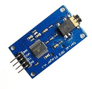
| MP3 Decoder | | MP3 Decoder | ||
| [https://www.amazon.com/HiLetgo-YX5300-Control-Serial-Arduino/dp/B0725RHR4D/ref=sr_1_6?crid=6LU06UQ364LS&keywords=hiletgo+mp3&qid=1638600984&sprefix=hiletgo+mp3%2Caps%2C220&sr=8-6 HiLetgo YX5300 UART Control Serial MP3 Music Player Module] | | [https://www.amazon.com/HiLetgo-YX5300-Control-Serial-Arduino/dp/B0725RHR4D/ref=sr_1_6?crid=6LU06UQ364LS&keywords=hiletgo+mp3&qid=1638600984&sprefix=hiletgo+mp3%2Caps%2C220&sr=8-6 HiLetgo YX5300 UART Control Serial MP3 Music Player Module] | ||
| Line 267: | Line 273: | ||
| $6.99 | | $6.99 | ||
|- | |- | ||
| − | ! scope="row"| | + | ! scope="row"| 5 |
| Power Adapter for LED Matrix | | Power Adapter for LED Matrix | ||
| [https://www.amazon.com/Belker-Adjustable-Universal-Household-Electronics/dp/B08LKRYFT6/ref=sr_1_1_sspa?crid=38ELM8WZ2X8T&keywords=belker+universal+ac+adapter&qid=1638603156&sprefix=belker+universal+%2Caps%2C238&sr=8-1-spons&psc=1&spLa=ZW5jcnlwdGVkUXVhbGlmaWVyPUExVko5T0JZTE9BMzkzJmVuY3J5cHRlZElkPUEwMzU2ODc3M0hNRlMzV1EyTk5RMiZlbmNyeXB0ZWRBZElkPUEwMDY0OTIxMVY1TEYwMTBQSVhCTyZ3aWRnZXROYW1lPXNwX2F0ZiZhY3Rpb249Y2xpY2tSZWRpcmVjdCZkb05vdExvZ0NsaWNrPXRydWU= Belker 36W Adapter ] | | [https://www.amazon.com/Belker-Adjustable-Universal-Household-Electronics/dp/B08LKRYFT6/ref=sr_1_1_sspa?crid=38ELM8WZ2X8T&keywords=belker+universal+ac+adapter&qid=1638603156&sprefix=belker+universal+%2Caps%2C238&sr=8-1-spons&psc=1&spLa=ZW5jcnlwdGVkUXVhbGlmaWVyPUExVko5T0JZTE9BMzkzJmVuY3J5cHRlZElkPUEwMzU2ODc3M0hNRlMzV1EyTk5RMiZlbmNyeXB0ZWRBZElkPUEwMDY0OTIxMVY1TEYwMTBQSVhCTyZ3aWRnZXROYW1lPXNwX2F0ZiZhY3Rpb249Y2xpY2tSZWRpcmVjdCZkb05vdExvZ0NsaWNrPXRydWU= Belker 36W Adapter ] | ||
| Line 273: | Line 279: | ||
| $15.00 | | $15.00 | ||
|- | |- | ||
| − | ! scope="row"| | + | ! scope="row"| 6 |
| XBee Module | | XBee Module | ||
| [https://www.amazon.com/XBee-2mW-Wire-Antenna-ZigBee/dp/B007R9U1QA/ref=sr_1_5?keywords=s1+international+xbee&qid=1638603432&sr=8-5 XBee 2mW Wire Antenna - Series 2C (ZigBee Mesh)] | | [https://www.amazon.com/XBee-2mW-Wire-Antenna-ZigBee/dp/B007R9U1QA/ref=sr_1_5?keywords=s1+international+xbee&qid=1638603432&sr=8-5 XBee 2mW Wire Antenna - Series 2C (ZigBee Mesh)] | ||
| Line 279: | Line 285: | ||
| $62.00 | | $62.00 | ||
|- | |- | ||
| − | ! scope="row"| | + | ! scope="row"| 7 |
| Joystick | | Joystick | ||
| [https://www.amazon.com/gp/product/B00P7QBGD2/ref=ppx_yo_dt_b_asin_title_o01_s00?ie=UTF8&psc=1 HiLetgo Game Joystick Sensor Game Controller] | | [https://www.amazon.com/gp/product/B00P7QBGD2/ref=ppx_yo_dt_b_asin_title_o01_s00?ie=UTF8&psc=1 HiLetgo Game Joystick Sensor Game Controller] | ||
| Line 285: | Line 291: | ||
| $4.89 | | $4.89 | ||
|- | |- | ||
| − | ! scope="row"| | + | ! scope="row"| 8 |
| Push Button Switch | | Push Button Switch | ||
| [https://anchor-electronics.com/ Anchor Electronics] | | [https://anchor-electronics.com/ Anchor Electronics] | ||
| Line 291: | Line 297: | ||
| $1.00 | | $1.00 | ||
|- | |- | ||
| − | ! scope="row"| | + | ! scope="row"| 9 |
| Jumper Cables | | Jumper Cables | ||
| [https://anchor-electronics.com/ Anchor Electronics] | | [https://anchor-electronics.com/ Anchor Electronics] | ||
| Line 297: | Line 303: | ||
| $7.00 | | $7.00 | ||
|- | |- | ||
| − | ! scope="row"| | + | ! scope="row"| 10 |
| Female headers for SJ2-PCB Connection | | Female headers for SJ2-PCB Connection | ||
| [https://www.google.com/maps/dir/San+Jos%C3%A9+State+University,+Washington+Sq,+San+Jose,+CA/anchor+electronics/@37.354066,-121.9429301,13z/data=!3m2!4b1!5s0x808fca25bba0d49f:0x7bbecf700459b959!4m13!4m12!1m5!1m1!1s0x808fccb864de43d5:0x397ffe721937340e!2m2!1d-121.8810715!2d37.3351874!1m5!1m1!1s0x808fca25ba26dfd5:0xc0ca43e28395709a!2m2!1d-121.960719!2d37.369187 Anchor Electronics] | | [https://www.google.com/maps/dir/San+Jos%C3%A9+State+University,+Washington+Sq,+San+Jose,+CA/anchor+electronics/@37.354066,-121.9429301,13z/data=!3m2!4b1!5s0x808fca25bba0d49f:0x7bbecf700459b959!4m13!4m12!1m5!1m1!1s0x808fccb864de43d5:0x397ffe721937340e!2m2!1d-121.8810715!2d37.3351874!1m5!1m1!1s0x808fca25ba26dfd5:0xc0ca43e28395709a!2m2!1d-121.960719!2d37.369187 Anchor Electronics] | ||
| Line 303: | Line 309: | ||
| $2.50 | | $2.50 | ||
|- | |- | ||
| − | ! scope="row"| | + | ! scope="row"| 11 |
| Ribbon Cable Connector for LED Matrix-PCB Connection | | Ribbon Cable Connector for LED Matrix-PCB Connection | ||
| Anchor Electronics | | Anchor Electronics | ||
| Line 309: | Line 315: | ||
| $1.00 | | $1.00 | ||
|- | |- | ||
| − | ! scope="row"| | + | ! scope="row"| 12 |
| Soldering Wire & 18 Gauge Wire | | Soldering Wire & 18 Gauge Wire | ||
| Anchor Electronics | | Anchor Electronics | ||
| Line 315: | Line 321: | ||
| $3.00 | | $3.00 | ||
|- | |- | ||
| − | ! scope="row"| | + | ! scope="row"| 13 |
| Copper Board for Game Controller Connections | | Copper Board for Game Controller Connections | ||
| Anchor Electronics | | Anchor Electronics | ||
| Line 481: | Line 487: | ||
== '''RGB Led Matrix''' == | == '''RGB Led Matrix''' == | ||
| − | The display in this project is a 64x64 RGB LED matrix panel with a scan rate of 1:32. The 4096 RGB LEDs in the LED matrix panel can each be individually controlled and addressed. The SJ-two board does not have enough GPIOs to support 4069 LEDs, so this LED Matrix uses just 13 digital GPIOs to provide complete control of each individual LED. The LED matrix does this by using a decoder to pick the rows and a 64-bit shift register to enable the desired color on the selected column. Data is placed into the shift register to choose the columns when the row selection is low. In this 64x64 LED matrix, which has six 64-bit shift registers for R1, G1, B1, R2, G2, B2, each color of the LED is controlled by one bit of the shift register. The display can only display 8 colors because it uses daisy-chained shift registers, which prevents PWM from being used to individually control each LED. The 5:32 decoders are used to control the LED matrix's top (Rows 0-31) and bottom (Rows 32-63) halves, respectively, as shown in the diagram below. Each of the lines A, B, C, D, and E of these decoders, which are used for row selection, has a 5-bit input. | + | The display in this project is a 64x64 RGB LED matrix panel with a scan rate of 1:32. The 4096 RGB LEDs in the LED matrix panel can each be individually controlled and addressed. The SJ-two board does not have enough GPIOs to support 4069 LEDs, so this LED Matrix uses just 13 digital GPIOs to provide complete control of each individual LED. The LED matrix does this by using a decoder to pick the rows and a 64-bit shift register to enable the desired color on the selected column. Data is placed into the shift register to choose the columns when the row selection is low. In this 64x64 LED matrix, which has six 64-bit shift registers for R1, G1, B1, R2, G2, and B2, each color of the LED is controlled by one bit of the shift register. The display can only display 8 colors because it uses daisy-chained shift registers, which prevents PWM from being used to individually control each LED. The 5:32 decoders are used to control the LED matrix's top (Rows 0-31) and bottom (Rows 32-63) halves, respectively, as shown in the diagram below. Each of the lines A, B, C, D, and E of these decoders, which are used for row selection, has a 5-bit input. |
How to illuminate an LED in the matrix: | How to illuminate an LED in the matrix: | ||
| Line 497: | Line 503: | ||
We opt to use the Power supply Module that came with the ELEGOO Upgraded Electronics Fun Kit rather than independently powering the SJ-two board, led matrix, and MP3 decoder. This supply module takes input via a barrel jack from a battery, a 12V power source, or any other source, and outputs 5V to our circuit as needed. To power a solderless breadboard layout, this module offers a cheap and practical way to convert a 7-12V wall plug into 5V and 3.3V. 700mA is the maximum output current. One 5V connector will link to the SJ-two board's Vcc, and the 64x64 led matrix will be powered by 5V. | We opt to use the Power supply Module that came with the ELEGOO Upgraded Electronics Fun Kit rather than independently powering the SJ-two board, led matrix, and MP3 decoder. This supply module takes input via a barrel jack from a battery, a 12V power source, or any other source, and outputs 5V to our circuit as needed. To power a solderless breadboard layout, this module offers a cheap and practical way to convert a 7-12V wall plug into 5V and 3.3V. 700mA is the maximum output current. One 5V connector will link to the SJ-two board's Vcc, and the 64x64 led matrix will be powered by 5V. | ||
| − | [[File: | + | [[File:elgo power module.jpg|center|500px|thumb|Power Module]] |
== '''LED Matrix and Controller Board Enclosure''' == | == '''LED Matrix and Controller Board Enclosure''' == | ||
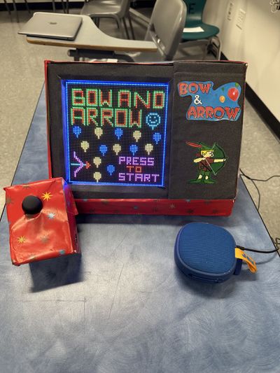
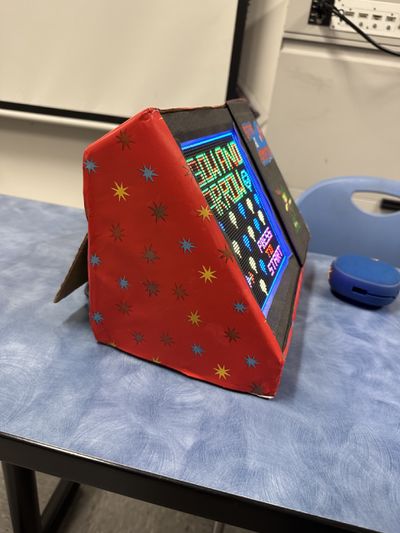
From the boxes we had on hand, we created the enclosures for our controller board and LED matrix. We positioned our matrix at an angle to provide the player with the best possible immersive experience. The controller board is not linked to the matrix enclosure, allowing the player to sit back, relax, and play the arcade game relatively comfortably. The controller board has its own enclosure, and the XBee module is used to communicate between the boards. | From the boxes we had on hand, we created the enclosures for our controller board and LED matrix. We positioned our matrix at an angle to provide the player with the best possible immersive experience. The controller board is not linked to the matrix enclosure, allowing the player to sit back, relax, and play the arcade game relatively comfortably. The controller board has its own enclosure, and the XBee module is used to communicate between the boards. | ||
| + | |||
| + | {| style="margin-left: auto; margin-right: auto; border: none;" | ||
| + | |[[File:Enclosure.jpeg|thumb|none|400px|Enclosure Front View]] | ||
| + | | | ||
| + | |[[File:Enclosure_2.jpeg|thumb|none|400px|Enclosure Side View]] | ||
| + | | | ||
| + | |} | ||
| + | |||
| + | |||
| Line 510: | Line 525: | ||
==== Hardware Design ==== | ==== Hardware Design ==== | ||
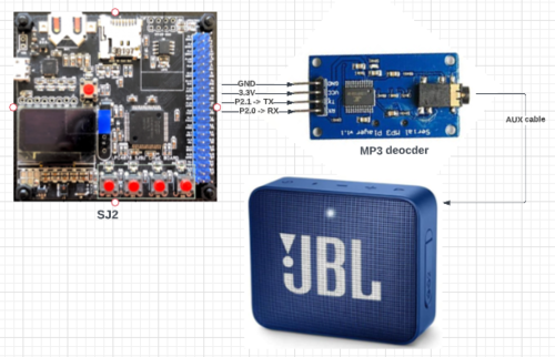
The UART Tx, UART Rx, VCC, and GND pins are the 4 pins that the MP3 decoder module needs. The SJ2 board provided the module with the 3.3V it needed to start up. On the SJ2 board, UART1 pins have been set up so that commands can be sent to the decoder. This UART communication's baud rate is set at 9600 bps. Additionally, this decoder has a speaker-connected 3.5mm audio jack. | The UART Tx, UART Rx, VCC, and GND pins are the 4 pins that the MP3 decoder module needs. The SJ2 board provided the module with the 3.3V it needed to start up. On the SJ2 board, UART1 pins have been set up so that commands can be sent to the decoder. This UART communication's baud rate is set at 9600 bps. Additionally, this decoder has a speaker-connected 3.5mm audio jack. | ||
| − | [[File: | + | |
| + | [[File:mp2 sj2 speaker.PNG|500px|thumb|center|Connection diagram of MP3 decoder to SJ2 board.]] | ||
==== Software Design ==== | ==== Software Design ==== | ||
| − | [[File: | + | [[File:mp3_software block diagram.PNG|thumb|center|MP3 Initialization]] |
| − | [[File: | + | [[File:mp3 music.PNG|center|600px|thumb|MP3 Music]] |
| Line 523: | Line 539: | ||
The Xbee module, button press, and joystick make up the controller board. A joystick is used to control character movement, while a button is used to activate the shoot arrow. Using ADC, the joystick reading is captured. We must enable burst mode on the ADC, which performs repeated conversion at 400 kHz, rather than reading a single value each time. Then, using Xbee, this information is transferred from the controller board to the mainboard (which houses the game logic and led drivers). Data is sent over UART after being received at the receiver end. The joystick ADC reading is represented by bits A0-A6 of the UART frame, whereas the button press data is represented by bit A7 of the frame. Blank data is sent if the button is not pressed. When an ISR is called after a UART interrupt, data is sent into the queue. The task that was dormant in the queue now awakens and, based on the data, moves the characters. | The Xbee module, button press, and joystick make up the controller board. A joystick is used to control character movement, while a button is used to activate the shoot arrow. Using ADC, the joystick reading is captured. We must enable burst mode on the ADC, which performs repeated conversion at 400 kHz, rather than reading a single value each time. Then, using Xbee, this information is transferred from the controller board to the mainboard (which houses the game logic and led drivers). Data is sent over UART after being received at the receiver end. The joystick ADC reading is represented by bits A0-A6 of the UART frame, whereas the button press data is represented by bit A7 of the frame. Blank data is sent if the button is not pressed. When an ISR is called after a UART interrupt, data is sent into the queue. The task that was dormant in the queue now awakens and, based on the data, moves the characters. | ||
| − | [[File: | + | [[File:BAR_block_diagram.PNG|center|800px|thumb|System Diagram]] |
| + | |||
Game Controller reading data from joystick and sending to UART logic | Game Controller reading data from joystick and sending to UART logic | ||
| Line 540: | Line 557: | ||
| − | == '' Configuring Xbee '' == | + | |
| + | == '''Configuring Xbee''' == | ||
| + | |||
You will most probably have to configure your XBee with XCTU software[https://www.digi.com/products/embedded-systems/digi-xbee/digi-xbee-tools/xctu link] and using the [https://www.amazon.com/waveshare-Adapter-Communication-Interface-Configure/dp/B07DMGF28S board link], before interfacing XBee with SJ2. Refer to this [https://www.youtube.com/watch?v=M-tTLYPumh8&ab_channel=MaheshPawaskar video link] to initially configure XBee. You will have to connect XBee with the board to your PC for configuration. | You will most probably have to configure your XBee with XCTU software[https://www.digi.com/products/embedded-systems/digi-xbee/digi-xbee-tools/xctu link] and using the [https://www.amazon.com/waveshare-Adapter-Communication-Interface-Configure/dp/B07DMGF28S board link], before interfacing XBee with SJ2. Refer to this [https://www.youtube.com/watch?v=M-tTLYPumh8&ab_channel=MaheshPawaskar video link] to initially configure XBee. You will have to connect XBee with the board to your PC for configuration. | ||
== '''Game Logic''' == | == '''Game Logic''' == | ||
| − | |||
| − | |||
| − | |||
| − | The game | + | The game starts at level one. The balloon creation task in level one produces repeated sets of four balloons until the player earns WIN SCORE (45 points) or runs out of arrows. Initially, there will be 10 arrows displayed in the upper right corner, and the count decreases with each arrow shot. The collision function, which is invoked by the shoot arrow task, checks to see if the arrowhead coordinates intersect with the balloon. If collided, the balloons turned black. For a full set to display again, one must shoot all four balloons. The player can advance to level 2 after scoring 45 points in 10 arrows. |
| − | The game's complexity | + | |
| + | The game's complexity is increased in level 2. In addition to randomizing balloon placement, we've also introduced rock-shaped impediments as a further challenge. There will be three lives available. If the player strikes the rock, the life count drops. Additionally, a player's score rises as they hit the balloons. The level is won if the player achieves a WIN SCORE (45 points) with fewer than or equal to ten arrows and fewer than or equal to three lives. To make the game more pleasant, we've limited the number of arrows to ten. | ||
| + | |||
| + | |||
[[File:Game flow.jpeg|center|800px|thumb|Game Logic]] | [[File:Game flow.jpeg|center|800px|thumb|Game Logic]] | ||
| + | |||
| + | |||
| + | We have implemented the collision logic for the balloon by the condition i.e. (if the arrows head coordinates are lesser than equal to than balloon's start row plus the balloon's height and arrowhead coordinates are lesser than equal to the balloon start column plus the balloon width), balloon collision is detected and player's score is increased by 5 points per each balloon. | ||
| + | So if the balloon_is_collided condition is true then the balloon disappear function gets called making the balloon color black. Concurrently game score task is called and the score gets increased by 5 points. The same logic is followed in level 1 and level 2. | ||
| + | |||
| + | |||
| + | [[File:Collision logic balloon level 1 and level 2.jpeg|center|800px|thumb|Collision Logic of Ballon]] | ||
| + | |||
| + | For level 2 as we have added rocks, the rock hit logic is implemented such that if the rock start row is lesser than equal to the arrowhead coordinates which is also less than the rock start row plus rock height, and the rock start column is lesser than equal to arrowhead coordinates which is also lesser than rock start column plus rock width --> rock collided is detected and lives count is reduced by one out of three. | ||
| + | If the rock collision is detected, the rock disappears function is called and as the live count is reduced, the make life disappears function will also get executed. | ||
| Line 557: | Line 586: | ||
| − | |||
| − | |||
| Line 564: | Line 591: | ||
== '''Scoring''' == | == '''Scoring''' == | ||
| + | |||
| + | {| style="margin-left: auto; margin-right: auto; border: none;" | ||
| + | |[[File:level score.PNG|none|700px|thumb|LEVEL 1 score logic]] | ||
| + | | | ||
| + | |[[File:level 2 score.PNG|right|700px|thumb|LEVEL 2 score logic]] | ||
| + | | | ||
| + | |} | ||
| + | |||
| + | == '''Game Tasks''' == | ||
| + | The figure below shows the FreeRTOS tasks that have been used in the Bow & Arrow game. | ||
| + | [[File:Bow&ArrowTask.png|center|800px|thumb|]] | ||
== '''Testing & Technical Challenges''' == | == '''Testing & Technical Challenges''' == | ||
| − | |||
| − | |||
| − | + | '''1.''' Along with the LED matrix and MP3 decoder, we have also wired the Xbee receiver directly to SJ2 using a pin-to-pin connection. The LED matrix screen would occasionally not turn on, but if we detached and reconnected the GND wire of the Xbee receiver, it would. | |
| − | + | '''2.''' The 33rd row of the LED matrix was shown on the first row, which was a problem we ran into early on in the project. This problem arose because we failed to reset the LED Matrix's Output Enable pin before clocking in the subsequent row of data. After carefully reading the Sparkfun article on RGB Matrix Panels, we were able to address this problem. | |
| − | + | ||
| + | '''3.''' Since our game has a lot of graphics, making a colorful, enjoyable screen was challenging and time-consuming. We discovered open-source software that, when receiving the photos as input, outputs a string of 1s and 0s. The gaming screens in our game are 2D matrices. The string of 64x64 characters required the painstaking addition of commas and braces to convert to matrices. Therefore, we created an automation script that, when the string is entered, outputs the final 64x64 matrix. | ||
| + | |||
| + | '''4.''' Rocks and balloons appear at random at stage 2, and overlapping was a significant problem. We created rows and columns (x and y coordinates) of balloons and rocks as members of structure object info. If the random number generator simultaneously produces pebbles and balloons, a new site must be selected. | ||
| + | |||
| + | '''5.'''Sounds get jumbled when a single file is edited individually. As sounds are referenced by folder and their index, the order gets ignored when sounds are saved individually. Rather, all the sounds need to be placed in SD card at the same instance. Else, they don't follow the order. The latest edited one precedes the older files. | ||
== '''Conclusion''' == | == '''Conclusion''' == | ||
This project was a huge success and a valuable teaching tool. Every module used for the project was effectively integrated, and we were able to reproduce our original game concept. The LED matrix was able to play the noises for each of the game components while loading our character moving, jumping, and separating balls. We also demonstrated our life and score tracking logic during the event. We encountered a number of challenges while working on the project, including issues starting the LED matrix driver, figuring out how to incorporate ballon and arrow collision detection, creating multiple ballons and creating randomly positioned balloons in level 2, designing and maintaining our complex game logic state machine, and much more. We were able to understand the real-world use of FreeRTOS while working on our project. We came to the conclusion that defining weekly goals and exceeding them could assist compartmentalize the project and eventually meet the desired outcome. This project improved our proficiency with embedded software and consolidated our command of it. | This project was a huge success and a valuable teaching tool. Every module used for the project was effectively integrated, and we were able to reproduce our original game concept. The LED matrix was able to play the noises for each of the game components while loading our character moving, jumping, and separating balls. We also demonstrated our life and score tracking logic during the event. We encountered a number of challenges while working on the project, including issues starting the LED matrix driver, figuring out how to incorporate ballon and arrow collision detection, creating multiple ballons and creating randomly positioned balloons in level 2, designing and maintaining our complex game logic state machine, and much more. We were able to understand the real-world use of FreeRTOS while working on our project. We came to the conclusion that defining weekly goals and exceeding them could assist compartmentalize the project and eventually meet the desired outcome. This project improved our proficiency with embedded software and consolidated our command of it. | ||
| + | ===''' Appendix''' === | ||
=== Project Video === | === Project Video === | ||
| − | + | ||
| + | * [https://www.youtube.com/watch?v=YMxCrv65DfI Demo Video Link] | ||
=== Project Source Code === | === Project Source Code === | ||
| − | * | + | |
| + | * [https://gitlab.com/thunderflash1/bow-and-arrow Project Source Code] | ||
=== Acknowledgement === | === Acknowledgement === | ||
| Line 591: | Line 635: | ||
# [https://www.riyas.org/2013/12/online-led-matrix-font-generator-with.html Binary code pattern generator for LED Matrix] | # [https://www.riyas.org/2013/12/online-led-matrix-font-generator-with.html Binary code pattern generator for LED Matrix] | ||
# [https://www.sparkfun.com/news/2650 Everything You Didn't Want to Know About RGB Matrix Panels] | # [https://www.sparkfun.com/news/2650 Everything You Didn't Want to Know About RGB Matrix Panels] | ||
| − | |||
| − | |||
| − | |||
| − | |||
| − | |||
| − | |||
Latest revision as of 03:56, 15 December 2022
Contents
- 1 Bow and Arrow
- 2 Abstract
- 3 Objectives & Introduction
- 4 Team Members & Technical Responsibilities
- 5 Administrative Responsibilities
- 6 Schedule
- 7 Bill Of Materials
- 8 Design & Implementation
- 8.1 PIN CONFIGURATION
- 8.2 RGB Led Matrix
- 8.3 Elegoo Power Supply Module
- 8.4 LED Matrix and Controller Board Enclosure
- 8.5 MP3 Decoder
- 8.6 Controller Board and Main Board Communication
- 8.7 Configuring Xbee
- 8.8 Game Logic
- 8.9 Scoring
- 8.10 Game Tasks
- 8.11 Testing & Technical Challenges
- 8.12 Conclusion
- 8.13 References Used
Bow and Arrow
Abstract
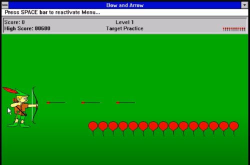
Bow and arrow is a fun, aiming archery game. Our goal was to create a similar version to the 1992 arcade game 'Bow and Arrow,' in which the player takes on the role of a skilled bowman on a quest to fight the dreaded Black Archer. There are two levels in our game. The challenges increase as the level advances. The player shoots the arrow at the balloons with a joystick. Before the arrows run out, the player must acquire a WIN SCORE. There are also rocks and three lives on the second level. When the player hits the rock, he loses one life. An LED matrix displays the entire game. In addition to visuals, the game has sound effects achieved using MP3. There is no timer in this score-based game. Enjoy the Game!
Objectives & Introduction
The main objective of this project was to create the “Bow and Arrow” video game displayed on a 64X64 RGB LED matrix, with one SJ2 board as a graphics processor/matrix controller, and another SJ2 board as a controller. Other objectives are the following:
- Use the FreeRTOS Real-Time Operating System on both SJ2 boards.
- Establish UART communications through Xbee between the two SJ-Two Microcontrollers.
- Create simple coding logic for displaying required characters and game objects.
- Add background music to the game to enhance the gameplay experience.
- Design custom PCBs for both the gamepad and matrix controller SJ2 boards.
HOW TO PLAY BOW AND ARROW:
The main aim of the game is to burst all the balloons and advance to the next level.
- Using the joystick on the game controller, move the bow up or down.
- Shoot arrows by pressing the joystick to burst the balloons.
Level 1
- Achieve a target score of 45 with the 10 provided arrows.
- If not game is over and the player can restart the level.
- If the level is won, press o start level 2.
Level 2
- Avoid hitting the rocks to not lose your life.
- Achieve a target score of 45 with the 10 provided arrows.
- If not, the game is over and the player goes back to level1.
Team Members & Technical Responsibilities
- Shreya Kulkarni
- Implementation and Integration of Graphics Driver
- Game logic design and Implementation
- Joystick Integration
- Pinky Mathew
- Interfacing of LED Matrix and driver design
- Game logic design and implementation
- Graphics driver design and implementation
- Joystick Integration
- Pushkar Deodhar
- Zigbee module and Joystick Driver design
- Integrating MP3 module with the Game
- Hardware Designing & PCB Integration
- Noel Smith
- MP3 Audio Encoder/Decoder Driver design
- Integrating MP3 player with the Game
- Hardware Designing & PCB Integration
Administrative Responsibilities
| Administrative Roles | ||||
|---|---|---|---|---|
|
Noel Smith | |||
|
Pinky Mathew | |||
|
Shreya Kulkarni | |||
|
Pushkar Deodhar | |||
Schedule
| Week# | Start Date | End Date | Task | Status |
|---|---|---|---|---|
| 1 |
|
|
|
|
| 2 |
|
|
|
|
| 3 |
|
|
|
|
| 4 |
|
|
|
|
| 5 |
|
|
|
|
| 6 |
|
|
|
|
| 7 |
|
|
|
|
| 8 |
|
|
|
|
| 9 |
|
|
|
|
| 10 |
|
|
|
|
Bill Of Materials
| Item# | Part Description | Part Model & Vendor | Quantity | Cost |
|---|---|---|---|---|
| 1 | Microcontroller Boards | SJ2 Boards (Purchased from Preet Kang) | 2 | $100.00 |
| 2 | LED Matrix Display | Adafruit RGB LED Matrix Panel - 64x64 | 1 | $87.95 |
| 3 | Electronics Fun Kit & Power Supply Module | ELEGOO Upgraded Electronics Fun Kit | 2 | $7.56 |
| 4 | MP3 Decoder | HiLetgo YX5300 UART Control Serial MP3 Music Player Module | 1 | $6.99 |
| 5 | Power Adapter for LED Matrix | Belker 36W Adapter | 1 | $15.00 |
| 6 | XBee Module | XBee 2mW Wire Antenna - Series 2C (ZigBee Mesh) | 2 | $62.00 |
| 7 | Joystick | HiLetgo Game Joystick Sensor Game Controller | 1 | $4.89 |
| 8 | Push Button Switch | Anchor Electronics | 1 | $1.00 |
| 9 | Jumper Cables | Anchor Electronics | 1 | $7.00 |
| 10 | Female headers for SJ2-PCB Connection | Anchor Electronics | 1 | $2.50 |
| 11 | Ribbon Cable Connector for LED Matrix-PCB Connection | Anchor Electronics | 1 | $1.00 |
| 12 | Soldering Wire & 18 Gauge Wire | Anchor Electronics | 1 | $3.00 |
| 13 | Copper Board for Game Controller Connections | Anchor Electronics | 1 | $4.00 |
| Total Cost | 22 | $317.89 |
Design & Implementation
PIN CONFIGURATION
-
Pin# SJ2 Main Board - LED Matrix Pin Configuration SJ-2 PIN R1 PIN for Red terminal of RGB LED for the upper half of LED Matrix P0_0 G1 PIN for Green terminal of RGB LED for the upper half of LED Matrix P0_1 B1 PIN for Blue terminal of RGB LED for the upper half of LED Matrix P2_2 R2 PIN for Red terminal of RGB LED for the lower half of LED Matrix P2_4 G2 PIN for Green terminal of RGB LED for the lower half of LED Matrix P2_5 B2 PIN for Blue terminal of RGB LED for the lower half of LED Matrix P2_6 A Mux pin for row selection P2_7 B Mux pin for row selection P2_8 C Mux pin for row selection P2_9 D Mux pin for row selection P0_16 E Mux pin for row selection P0_15 OE Output Enable P1_28 LATCH Data Latch P1_29 CLK Clock Signal P0_17 MP3 Decoder RX UART Receive From MP3 Decoder P2_1 TX UART Send Command from SJ-2 Main Board P2_0 XBEE Module Receiver RX UART Receive From Game Controller P0_11 VCC VCC Supply VCC 3.3 -
Pin# Controller Board Pin Configuration uC PIN XBEE Module Transmitter TX UART Transmit to Main Board P0_10 VCC VCC Supply VCC 3.3 Joystick VCC VCC 3.3V GND GND GND Vx X-axis ADC Reading for character movement P0_25 Push Button I/0 Pin Arrow Shooting P1_29
RGB Led Matrix
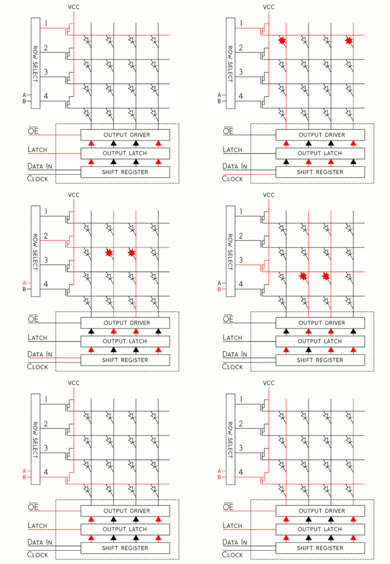
The display in this project is a 64x64 RGB LED matrix panel with a scan rate of 1:32. The 4096 RGB LEDs in the LED matrix panel can each be individually controlled and addressed. The SJ-two board does not have enough GPIOs to support 4069 LEDs, so this LED Matrix uses just 13 digital GPIOs to provide complete control of each individual LED. The LED matrix does this by using a decoder to pick the rows and a 64-bit shift register to enable the desired color on the selected column. Data is placed into the shift register to choose the columns when the row selection is low. In this 64x64 LED matrix, which has six 64-bit shift registers for R1, G1, B1, R2, G2, and B2, each color of the LED is controlled by one bit of the shift register. The display can only display 8 colors because it uses daisy-chained shift registers, which prevents PWM from being used to individually control each LED. The 5:32 decoders are used to control the LED matrix's top (Rows 0-31) and bottom (Rows 32-63) halves, respectively, as shown in the diagram below. Each of the lines A, B, C, D, and E of these decoders, which are used for row selection, has a 5-bit input.
How to illuminate an LED in the matrix:
- Represent the color you want to appear on the board using three bits.
- Choose whether you want to light an LED that is on the board's UPPER or LOWER side, and then adjust RGB1 or RGB2 pins accordingly.
- To set the bits and clock them in with the other LEDs, toggle the CLK (You can set the other LEDs to be off by clocking in zero)
- Once a full row has been entered, disable Output and set Latch High.
- Using the A, B, C, D, and E pins, indicate which row your target LED is on.
- Reactivate the Output and lower the Latch's value.
Elegoo Power Supply Module
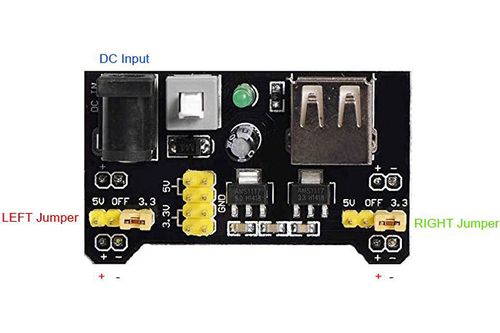
We opt to use the Power supply Module that came with the ELEGOO Upgraded Electronics Fun Kit rather than independently powering the SJ-two board, led matrix, and MP3 decoder. This supply module takes input via a barrel jack from a battery, a 12V power source, or any other source, and outputs 5V to our circuit as needed. To power a solderless breadboard layout, this module offers a cheap and practical way to convert a 7-12V wall plug into 5V and 3.3V. 700mA is the maximum output current. One 5V connector will link to the SJ-two board's Vcc, and the 64x64 led matrix will be powered by 5V.
LED Matrix and Controller Board Enclosure
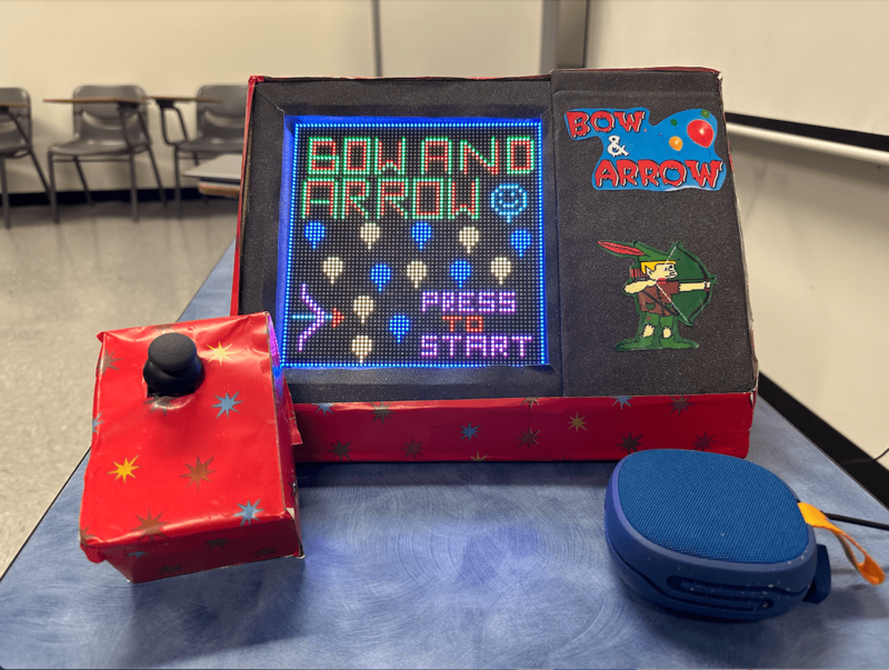
From the boxes we had on hand, we created the enclosures for our controller board and LED matrix. We positioned our matrix at an angle to provide the player with the best possible immersive experience. The controller board is not linked to the matrix enclosure, allowing the player to sit back, relax, and play the arcade game relatively comfortably. The controller board has its own enclosure, and the XBee module is used to communicate between the boards.
MP3 Decoder
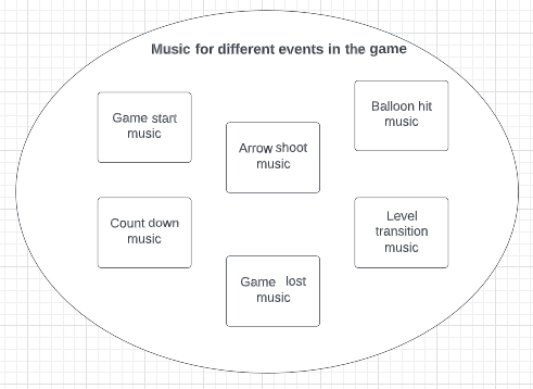
This module is a straightforward MP3 player that runs on the YX5300 high-quality MP3 audio chip. MP3 and WAV file formats with sampling rates of 8 kHz to 48 kHz are supported. The micro SD card used to store the audio files can be inserted because there is a TF card socket on the board. By sending commands to the module via the UART interface, the MCU can control the MP3 playback state by altering the volume, switching tracks, etc.
Hardware Design
The UART Tx, UART Rx, VCC, and GND pins are the 4 pins that the MP3 decoder module needs. The SJ2 board provided the module with the 3.3V it needed to start up. On the SJ2 board, UART1 pins have been set up so that commands can be sent to the decoder. This UART communication's baud rate is set at 9600 bps. Additionally, this decoder has a speaker-connected 3.5mm audio jack.
Software Design
Controller Board and Main Board Communication
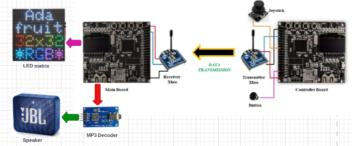
You may quickly configure XBees, test connections, and pass data between your computer and remote XBees by connecting an XBee Explorer between your computer and your XBee and using the X-CTU software. We utilize X-CTU, free software offered by Digi (the XBee maker), to set up, manage, and test XBee networks. An excellent step-by-step instruction for configuring the Xbees as a transmitter and receiver can be found on the SparkFun website at here. The Xbee module, button press, and joystick make up the controller board. A joystick is used to control character movement, while a button is used to activate the shoot arrow. Using ADC, the joystick reading is captured. We must enable burst mode on the ADC, which performs repeated conversion at 400 kHz, rather than reading a single value each time. Then, using Xbee, this information is transferred from the controller board to the mainboard (which houses the game logic and led drivers). Data is sent over UART after being received at the receiver end. The joystick ADC reading is represented by bits A0-A6 of the UART frame, whereas the button press data is represented by bit A7 of the frame. Blank data is sent if the button is not pressed. When an ISR is called after a UART interrupt, data is sent into the queue. The task that was dormant in the queue now awakens and, based on the data, moves the characters.
Game Controller reading data from joystick and sending to UART logic
void read_joystick_and_send(void *p) {
  while (1) {
    uint16_t joystick_reading = adc__get_channel_reading_with_burst_mode(ADC__CHANNEL_2);
    joystick_reading = (joystick_reading * 125) / 4095;
    if (!(LPC_GPIO1->PIN & (1 << 31)))
      joystick_reading |= 1 << 7;
    uart_lab__polled_put(2, joystick_reading);
    vTaskDelay(5);
  }
}
Configuring Xbee
You will most probably have to configure your XBee with XCTU softwarelink and using the board link, before interfacing XBee with SJ2. Refer to this video link to initially configure XBee. You will have to connect XBee with the board to your PC for configuration.
Game Logic
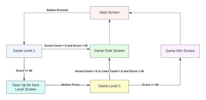
The game starts at level one. The balloon creation task in level one produces repeated sets of four balloons until the player earns WIN SCORE (45 points) or runs out of arrows. Initially, there will be 10 arrows displayed in the upper right corner, and the count decreases with each arrow shot. The collision function, which is invoked by the shoot arrow task, checks to see if the arrowhead coordinates intersect with the balloon. If collided, the balloons turned black. For a full set to display again, one must shoot all four balloons. The player can advance to level 2 after scoring 45 points in 10 arrows.
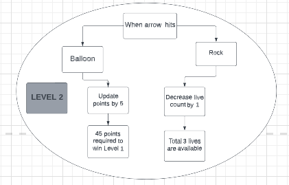
The game's complexity is increased in level 2. In addition to randomizing balloon placement, we've also introduced rock-shaped impediments as a further challenge. There will be three lives available. If the player strikes the rock, the life count drops. Additionally, a player's score rises as they hit the balloons. The level is won if the player achieves a WIN SCORE (45 points) with fewer than or equal to ten arrows and fewer than or equal to three lives. To make the game more pleasant, we've limited the number of arrows to ten.
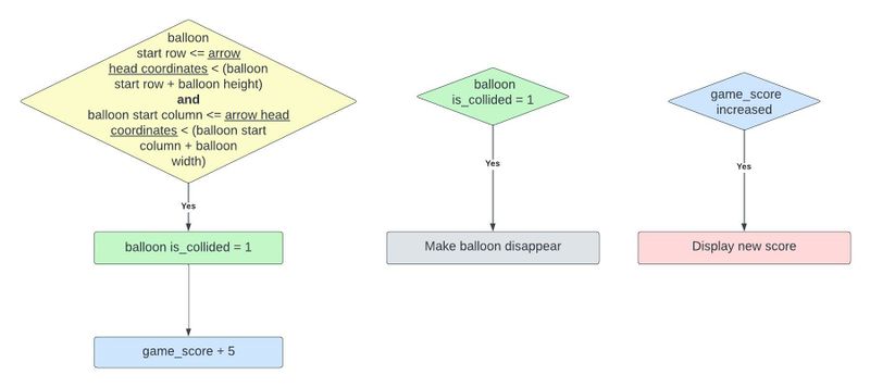
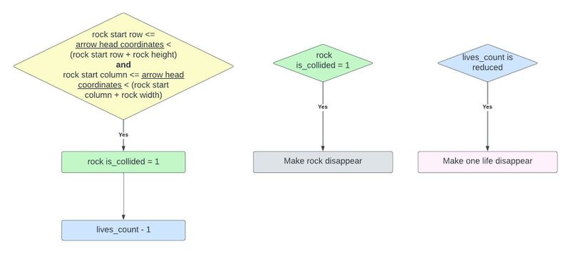
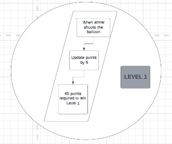
We have implemented the collision logic for the balloon by the condition i.e. (if the arrows head coordinates are lesser than equal to than balloon's start row plus the balloon's height and arrowhead coordinates are lesser than equal to the balloon start column plus the balloon width), balloon collision is detected and player's score is increased by 5 points per each balloon.
So if the balloon_is_collided condition is true then the balloon disappear function gets called making the balloon color black. Concurrently game score task is called and the score gets increased by 5 points. The same logic is followed in level 1 and level 2.
For level 2 as we have added rocks, the rock hit logic is implemented such that if the rock start row is lesser than equal to the arrowhead coordinates which is also less than the rock start row plus rock height, and the rock start column is lesser than equal to arrowhead coordinates which is also lesser than rock start column plus rock width --> rock collided is detected and lives count is reduced by one out of three. If the rock collision is detected, the rock disappears function is called and as the live count is reduced, the make life disappears function will also get executed.
In our Bow and Arrow project, the command we use to play the songs is by navigating to its index on the SD card. In our code, the function that sends this command is referred to as playing music at the index. We must first send the command [Select device] before we can send the instruction to play music at a specific index. The datasheet specifies that you should send "7E FF 06 09 00 00 02 EF" since Serial MP3 Player only accepts micro SD cards. Additionally, the function UART polled put on UART1 is being used to transmit the commands.
Scoring
Game Tasks
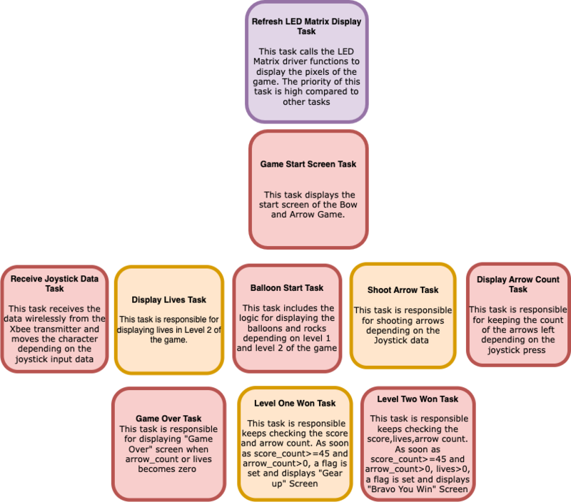
The figure below shows the FreeRTOS tasks that have been used in the Bow & Arrow game.
Testing & Technical Challenges
1. Along with the LED matrix and MP3 decoder, we have also wired the Xbee receiver directly to SJ2 using a pin-to-pin connection. The LED matrix screen would occasionally not turn on, but if we detached and reconnected the GND wire of the Xbee receiver, it would.
2. The 33rd row of the LED matrix was shown on the first row, which was a problem we ran into early on in the project. This problem arose because we failed to reset the LED Matrix's Output Enable pin before clocking in the subsequent row of data. After carefully reading the Sparkfun article on RGB Matrix Panels, we were able to address this problem.
3. Since our game has a lot of graphics, making a colorful, enjoyable screen was challenging and time-consuming. We discovered open-source software that, when receiving the photos as input, outputs a string of 1s and 0s. The gaming screens in our game are 2D matrices. The string of 64x64 characters required the painstaking addition of commas and braces to convert to matrices. Therefore, we created an automation script that, when the string is entered, outputs the final 64x64 matrix.
4. Rocks and balloons appear at random at stage 2, and overlapping was a significant problem. We created rows and columns (x and y coordinates) of balloons and rocks as members of structure object info. If the random number generator simultaneously produces pebbles and balloons, a new site must be selected.
5.Sounds get jumbled when a single file is edited individually. As sounds are referenced by folder and their index, the order gets ignored when sounds are saved individually. Rather, all the sounds need to be placed in SD card at the same instance. Else, they don't follow the order. The latest edited one precedes the older files.
Conclusion
This project was a huge success and a valuable teaching tool. Every module used for the project was effectively integrated, and we were able to reproduce our original game concept. The LED matrix was able to play the noises for each of the game components while loading our character moving, jumping, and separating balls. We also demonstrated our life and score tracking logic during the event. We encountered a number of challenges while working on the project, including issues starting the LED matrix driver, figuring out how to incorporate ballon and arrow collision detection, creating multiple ballons and creating randomly positioned balloons in level 2, designing and maintaining our complex game logic state machine, and much more. We were able to understand the real-world use of FreeRTOS while working on our project. We came to the conclusion that defining weekly goals and exceeding them could assist compartmentalize the project and eventually meet the desired outcome. This project improved our proficiency with embedded software and consolidated our command of it.
Appendix
Project Video
Project Source Code
Acknowledgement
We would like to thank Professor Preetpal Kang for sharing his knowledge and insights with us during the course of the project.
