Difference between revisions of "S22: TBD"
(→Drive Logic) |
(→LCD Implementation) |
||
| (4 intermediate revisions by the same user not shown) | |||
| Line 622: | Line 622: | ||
A simple algorithm was used to determine the PWM signal sent to the steering servos. We decide to have the driver node send a direction between the values of -180 to 179. After some quick testing with the values, we found the range to be much larger than then we required to get the steering to be a fluid motion. To solve this, we had our firmware treat any signal above 40 and below -40 to be max right and left respectively. We then had to scale the values within that range using the algorithm in the flow chart above. | A simple algorithm was used to determine the PWM signal sent to the steering servos. We decide to have the driver node send a direction between the values of -180 to 179. After some quick testing with the values, we found the range to be much larger than then we required to get the steering to be a fluid motion. To solve this, we had our firmware treat any signal above 40 and below -40 to be max right and left respectively. We then had to scale the values within that range using the algorithm in the flow chart above. | ||
| + | |||
| + | Steering Algorithm code snippet showing the scaling duty cycle outside of the +/- 40 range sent from driver. | ||
| + | |||
| + | <syntaxhighlight lang="cpp"> | ||
| + | void motor_controller__set_direction(int16_t direction) { | ||
| + | if (direction < -40) { | ||
| + | motor_controller__set_direction_pwm_cycle(11.96); // 6.66 | ||
| + | } else if (direction > 40) { | ||
| + | motor_controller__set_direction_pwm_cycle(6.66); | ||
| + | } else { | ||
| + | float duty_cycle = (9.31 - (direction / 40.0) * 2.65); | ||
| + | motor_controller__set_direction_pwm_cycle(duty_cycle); | ||
| + | } | ||
| + | } | ||
| + | </syntaxhighlight> | ||
'''Forward Backward Algorithm''' | '''Forward Backward Algorithm''' | ||
| Line 1,002: | Line 1,017: | ||
===LCD Implementation=== | ===LCD Implementation=== | ||
| − | The LCD needed to be set to 4-bit mode with specific delays, enables and functionality. The LCD data is set in two formats. One is for displaying characters on the screen using | + | The LCD needed to be set to 4-bit mode with specific delays, enables and functionality. The LCD data is set in two formats. One is for displaying characters on the screen using ASCII. The hex ASCII value is sent 4 times. Each time is sent, the first four bits are based on the ASCII hex value. For example, 'a' is 0x1C, therefore the first four bits for the first two writes will be 0x1 and the other two will be 0xC. The other four bits are for setting brightness, enable, r/w, and select. The other format is command send, which is for implementation purposes, or location setting. It follows the same methodology as sending characters, but the select is off for all four transmissions. To write to the display, we would need to send a command to set the location of the message. Then we need to send the actual data as a string. If it is a short string, the rest of the pixels need to be set to empty spaces. This is necessary to display values that are constantly being updated. If not set, the LCD would display old characters. This is call at 100Hz in periodic callbacks. |
| Line 1,037: | Line 1,052: | ||
[[File:Drive_logic.PNG|400px|Driver Algorithm]] | [[File:Drive_logic.PNG|400px|Driver Algorithm]] | ||
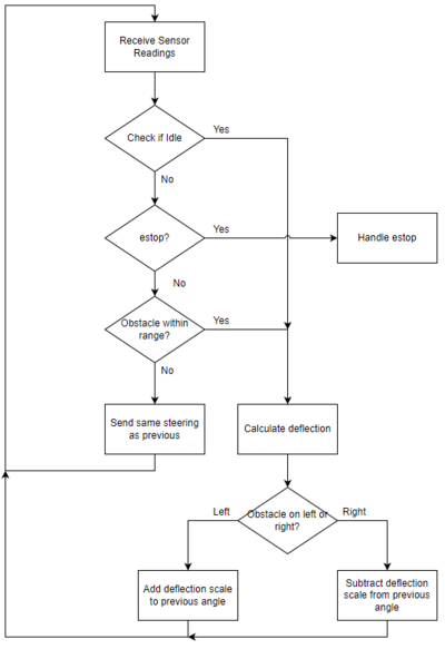
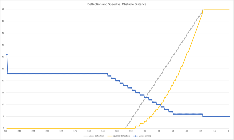
| − | The above flowchart shows the high level overview of our driver logic which begins with receiving sensor values from the sensor controller. The first check is to see if we are currently idle or not. This is the one check that will override all others, including emergency stop thresholds. We decided on this design since there are no real breaks for the car, we wanted to be able to steer as the car is coming to a stop. Emergency stop is handled in a different routine, thus we had to make this check first to obtain the desired functionality. If the car is not in the idle state, then we next check the sensor values to see if any are within the emergency stop threshold which we set to 30cm or 1 foot. If any of the readings indicated this, then we went to the emergency stop routine, described below. If the sensor readings all read above the emergency stop threshold, then we check to see if there is an obstacle within our next threshold. The threshold to detect an obstacle is 140cm. This value was chosen because of the sensor configuration giving most accurate values up to this distance. When an obstacle is detected, we perform a deflection calculation which would give us a linear mapping of how much to change the steering angle depending on how far away it was from the car. The closer the obstacle, the harsher the steering angle we would send. If no obstacle was in the threshold value, then we simply sent the same steering that was calculated according to our destination and current heading. | + | The above flowchart shows the high level overview of our driver logic which begins with receiving sensor values from the sensor controller. The first check is to see if we are currently idle or not. This is the one check that will override all others, including emergency stop thresholds. We decided on this design since there are no real breaks for the car, we wanted to be able to steer as the car is coming to a stop. Emergency stop is handled in a different routine, thus we had to make this check first to obtain the desired functionality. If the car is not in the idle state, then we next check the sensor values to see if any are within the emergency stop threshold which we set to 30cm or 1 foot. If any of the readings indicated this, then we went to the emergency stop routine, described below. If the sensor readings all read above the emergency stop threshold, then we check to see if there is an obstacle within our next threshold. The threshold to detect an obstacle is 140cm. This value was chosen because of the sensor configuration giving most accurate values up to this distance. When an obstacle is detected, we perform a deflection calculation which would give us a linear mapping of how much to change the steering angle depending on how far away it was from the car. The closer the obstacle, the harsher the steering angle we would send. If no obstacle was in the threshold value, then we simply sent the same steering that was calculated according to our destination and current heading. The correlation between deflection/motor speed and obstacle distance is illustrated in the diagram below. |
| + | |||
| + | [[File:Obstacle_plot.png|800px]] | ||
'''Emergency Stop''' | '''Emergency Stop''' | ||
| Line 1,142: | Line 1,159: | ||
== Conclusion == | == Conclusion == | ||
| − | Overall this project taught us many industry relevant topics. We were able to utilize and understand the CAN Bus to create a realistic self-driving RC car which emulated how a real car would function. Different controllers were used for: | + | Overall this project taught us many industry relevant topics. We were able to utilize and understand the CAN Bus to create a realistic self-driving RC car which emulated how a real car would function. Different controllers were used for: obtaining geological and position related data, obtain RPM and distance data through various sensors, control steering servo and control forward/ reverse speed, and a singular driver controller to control logic. |
| + | |||
| + | Some of the key take-aways and learnings from this project: | ||
| + | * Working with a team is not always easy. Having defined goals for each person to complete is important. LIST THEM OUT, don't just say what each person will do. | ||
| + | * Testing location matters. The performance of our vehicle improved greatly once we moved outdoors. | ||
| + | * CAN Bus is robust, definitely more so than our software and hardware implementations. Never was the root cause of an issue CAN bus. It was always root caused as something we did or designed. | ||
| − | |||
=== Project Video === | === Project Video === | ||
| Line 1,166: | Line 1,187: | ||
* Once your car can move, test outside on the garage. | * Once your car can move, test outside on the garage. | ||
** Ultrasonic sensors give incorrect readings at steep angles, making testing in the hallway somewhat difficult. | ** Ultrasonic sensors give incorrect readings at steep angles, making testing in the hallway somewhat difficult. | ||
| − | ** Compass readings are also more accurate outside the building where there is less | + | ** Compass readings are also more accurate outside the building where there is less interference. |
| + | * Lastly and most importantly, trust yourselves. This project is daunting, but Preet has laid it out in a way that gives you little milestones that come together to a complete project. | ||
=== Acknowledgement === | === Acknowledgement === | ||
| − | We would like to acknowledge our instructor, Preet, for encouraging us to gather knowledge and to tackle difficult problems. | + | We would like to acknowledge our instructor, Preet, for encouraging us to gather knowledge and to tackle difficult problems. We would also like to thank him for sharing his industry experience and providing us with a class and project that will be beneficial for us and our success in the industry going forward. |
=== References === | === References === | ||
Latest revision as of 06:43, 28 May 2022
Contents
Project Title
THE BEST DRIVER
Abstract
Our goal for this project is to use knowledge we gathered from lectures to design, implement, and test a self-driving RC car using a Controller Area Network (CAN) bus for controller communication. The project involves FreeRTOS and utilizes periodic tasks (running at 1Hz, 10Hz, and 100Hz) to gather, process, and display data from various embedded modules.
Introduction
The project was divided into 5 modules:
- Sensor/Bridge Controller
- Motor Controller
- Geo Controller
- Driver/LCD Controller
- Web Application
Team Members & Responsibilities
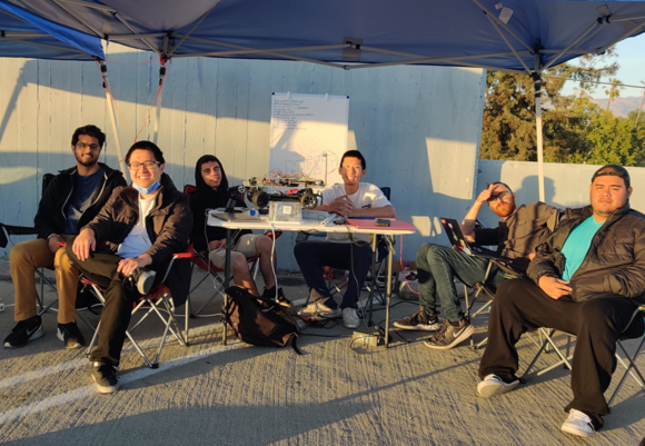
From Left to Right: Jasdip Sekhon, Brian Ho, Justin Stokes, Billy Lai, Isaac Wahhab, William Hernandez
- Sensor
- Jasdip Sekhon
- Brian Ho
- Justin Stokes
- Motor
- Justin Stokes
- Isaac Wahhab
- Geographical
- Brian Ho
- William Hernandez
- Jasdip Sekhon
- Driver Logic & LCD & LED Ring
- William Hernandez
- Billy Lai
- Isaac Wahhab
- Web Application & Communication Bridge Controller
- Isaac Wahhab
- Billy Lai
- Testing Team
- The Best Driver Team
Schedule
| Week# | Start Date | End Date | Task | Status |
|---|---|---|---|---|
| 1 | 02/15/2022 | 02/21/2022 |
|
Completed |
| 2 | 02/22/2022 | 02/28/2022 |
|
Completed |
| 3 | 03/01/2022 | 03/07/2022 |
|
Completed |
| 4 | 03/08/2022 | 03/14/2022 |
|
Completed |
| 5 | 03/15/2022 | 03/21/2022 |
|
Completed |
| 6 | 03/22/2022 | 03/28/2022 |
|
Completed |
| 7 | 03/29/2022 | 04/04/2022 |
|
Completed |
| 8 | 04/05/2022 | 04/11/2022 |
|
Completed |
| 9 | 04/12/2022 | 04/18/2022 |
|
Completed |
| 10 | 04/19/2022 | 04/25/2022 |
|
Completed |
| 11 | 04/26/2022 | 05/02/2022 |
|
Completed |
| 12 | 05/03/2022 | 05/09/2022 |
|
Completed |
| 13 | 05/10/2022 | 05/16/2022 |
|
Completed |
| 14 | 05/17/2022 | 05/25/2022 |
|
Completed |
Parts List & Cost
| Item# | Part Desciption | Vendor | Qty | Cost |
|---|---|---|---|---|
| 1 | RC Car | Redcat Racing | 1 | $139.00 |
| 2 | SJTwo Boards | SJTwo Boards On Amazon | 4 | $200.00 |
| 3 | CAN Transceivers (SN65HVD230) | Waveshare | 4 | $40.00 |
| 4 | LSM303 Triple-Axis Accelerometer and Magnetometer | Adafruit | 1 | $15.00 |
| 5 | Venus GPS with SMA Connector | SparkFun | 1 | |
| 6 | URM09 Ultrasonic Sensors | DFRobot Gravity | 4 | $52.00 |
| 7 | PCB | JLCPCB | 1 | $5.00 |
| 8 | Plexiglass | TAP Plastics | 1 | $15.00 |
| 9 | LCD Display | SunFounder LCD Display | 1 | $12.99 |
| 10 | APA102 Ring LED | Sparkfun | 1 | $11.50 |
| 11 | LEDs for obstacle detection, GPS lock status, and web app lock status | 6 | ||
| 12 | Rotary Encoder & Wheel Set | Tinkersphere | 2 | $10.99 |
| 13 | Set of Headlights and taillights | eBay | 1 | $3.99 |
| 14 | Logic Level Converters | Sparkfun | 1 | $3.50 |
| 15 | Buck Converters | 1 | ||
| 16 | Standoffs for mounting SJTwo boards, PCB, and raising compass | 40 |
Printed Circuit Board
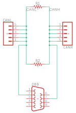
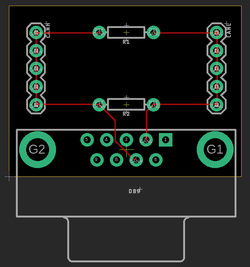
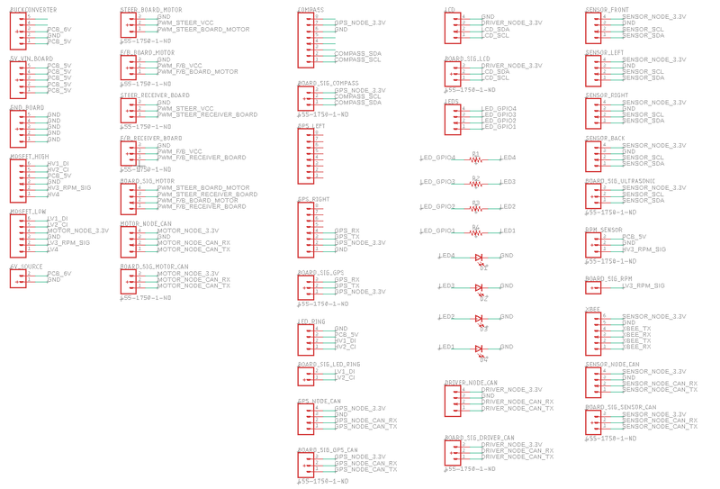
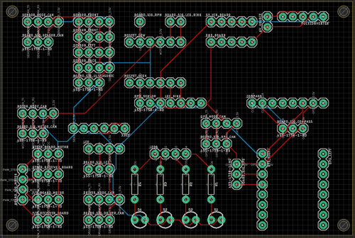
We designed and implemented two PCBs: CAN Bus PCB and RC Car PCB.
CAN Bus PCB Schematic
CAN Bus PCB Board
RC Car PCB Schematic
RC Car PCB Board
CAN Communication
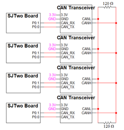
Our message IDs are arranged with priority given to the nodes in the following order: DRIVER, SENSOR, GEO, MOTOR. The following critical messages are transmitted at 100Hz:
- SENSOR_TO_DRIVER_SONARS
- GPS_DESTINATION_LOCATION
- SENSOR_TO_DRIVER_WHEEL_ENCODER_MSG
- GEO_STATUS
- DRIVER_TO_MOTOR_CMD
The remaining debug messages are transmitted at 10Hz or 1Hz.
We decided to give 32 message IDs to each node and to separate the nodes' message IDs accordingly.
| Node | Message ID Range | |
|---|---|---|
| 1 | DRIVER | 32 - 63 |
| 2 | SENSOR | 63 - 95 |
| 3 | GEO | 96 - 127 |
| 4 | MOTOR | 128 - 159 |
Hardware Design
DBC File
Gitlab link to our master branch's DBC file
Our DBC file includes the SENSOR, DRIVER, MOTOR, and GEO nodes.
Below are the messages defined in the file:
BO_ 32 DRIVER_TO_MOTOR_CMD: 3 DRIVER
 SG_ DRIVER_TO_MOTOR_steer : 0|9@1+ (1,-180) [-180|179] "" MOTOR
 SG_ DRIVER_TO_MOTOR_speed : 9|5@1+ (1,0) [0|31] "RPM" MOTOR
 SG_ DRIVER_TO_MOTOR_current_rpm : 14|10@1+ (1,0) [0|1023] "RPM" MOTOR
BO_ 33 DRIVER_DEBUG_MSG: 1 DRIVER
 SG_ DRIVER_DEBUG_MSG_sensor_mia : 0|1@1+ (1,0) [0|0] "" DBG
 SG_ DRIVER_DEBUG_MSG_geo_mia : 1|1@1+ (1,0) [0|0] "" DBG
BO_ 64 SENSOR_TO_DRIVER_SONARS: 4 SENSOR
 SG_ SENSOR_TO_DRIVER_SONARS_front_left : 0|8@1+ (1,0) [0|0] "" DRIVER
 SG_ SENSOR_TO_DRIVER_SONARS_front_middle : 8|8@1+ (1,0) [0|0] "" DRIVER
 SG_ SENSOR_TO_DRIVER_SONARS_front_right : 16|8@1+ (1,0) [0|0] "" DRIVER
 SG_ SENSOR_TO_DRIVER_SONARS_back : 24|8@1+ (1,0) [0|0] "" DRIVER
BO_ 65 GPS_DESTINATION_LOCATION: 7 SENSOR
 SG_ GPS_DESTINATION_LOCATION_latitude : 0|28@1+ (0.000001,-134.217727) [-134.217727|134.217728] "" GEO,DRIVER
 SG_ GPS_DESTINATION_LOCATION_longitude : 28|28@1+ (0.000001,-134.217727) [-134.217728|134.217728] "" GEO,DRIVER
BO_ 66 SENSOR_TO_DRIVER_WHEEL_ENCODER_MSG: 2 SENSOR
 SG_ SENSOR_TO_DRIVER_WHEEL_ENCODER_MSG_rpm : 0|10@1+ (1,0) [0|0] "RPM" DRIVER,DBG
BO_ 67 SENSOR_TO_DRIVER_APP_CONNECTION_MSG: 1 SENSOR
 SG_ SENSOR_TO_DRIVER_APP_CONNECTION_MSG_app_connected : 0|1@1+ (1,0) [0|0] "" DRIVER
BO_ 96 GEO_STATUS: 5 GEO
  SG_ GEO_STATUS_compass_heading : 0|9@1+ (1,0) [0|359] "Degrees" SENSOR,DRIVER
  SG_ GEO_STATUS_destination_heading : 9|9@1+ (1,0) [0|359] "Degrees" SENSOR,DRIVER
  SG_ GEO_STATUS_distance_to_destination : 18|16@1+ (0.1,0) [0|0] "Meters" SENSOR,DRIVER
BO_ 97 GEO_DEBUG_MSG: 1 GEO
  SG_ GEO_DEBUG_MSG_lock_status : 0|1@1+ (1,0) [0|0] "" DRIVER,DBG
  SG_ GEO_DEBUG_MSG_num_satellites : 1|4@1+ (1,0) [0|15] "" DRIVER,DBG
BO_ 98 GEO_CURRENT_LOCATION_DEBUG: 7 GEO
  SG_ GEO_CURRENT_LOCATION_DEBUG_latitude : 0|28@1+ (0.000001,-134.217727) [-134.217727|134.217728] "" DRIVER,DBG
  SG_ GEO_CURRENT_LOCATION_DEBUG_longitude : 28|28@1+ (0.000001,-134.217727) [-134.217728|134.217728] "" DRIVER,DBG
BO_ 99 GEO_CURRENT_DESTINATION_LOCATION_DEBUG: 7 GEO
  SG_ GEO_CURRENT_DESTINATION_LOCATION_DEBUG_latitude : 0|28@1+ (0.000001,-134.217727) [-134.217727|134.217728] "" SENSOR,DBG
  SG_ GEO_CURRENT_DESTINATION_LOCATION_DEBUG_longitude : 28|28@1+ (0.000001,-134.217727) [-134.217728|134.217728] "" SENSOR,DBG
BO_ 128 MOTOR_DEBUG_MSG: 3 MOTOR
 SG_ MOTOR_DEBUG_MSG_echo_steer : 0|3@1+ (1,-2) [-2|2] "" DBG
 SG_ MOTOR_DEBUG_MSG_echo_speed : 3|5@1+ (1,0) [0|31] "RPM" DBG
 SG_ MOTOR_DEBUG_MSG_echo_rpm : 8|10@1+ (1,0) [0|1023] "RPM" DBG
MIA Management
Since the DRIVER node is our main controller, we conducted MIA management in the driver_logic code module.
Our MIA management is serviced at 10Hz and ensures that the expected messages are received within a time limit set by threshold values.
If a message goes "missing" past set threshold times, a default replacement value is used.
The MIA threshold values and replacement structures are found in the can_mia_configurations.c file.
SENSOR_TO_DRIVER_SONARS
- Default value in the DRIVER node is to set the sensor values to 0. This will result in the driver_logic simulating obstacles detected at 0cm in the front and back, and the car will not move.
GPS_DESTINATION_LOCATION
- Default value in the GEO node is to set the current coordinates and destination coordinates to 0. This will result in a 0 distance_to_destination calculation, and the DRIVER node will subsequently send an IDLE speed to the MOTOR node.
GEO_STATUS
- Default value in the DRIVER node is to set compass heading, destination heading, and distance to destination to 0. This will result in the ring LED not lighting up (to show an invalid state) and the DRIVER will send an IDLE speed to the MOTOR node.
DRIVER_TO_MOTOR_CMD
- Default value in the MOTOR node is to set the motor speed and steering to IDLE and 0, respectively. Without updated driver to motor commands, the RC car should not move.
Sensor Controller
Hardware Design
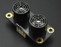
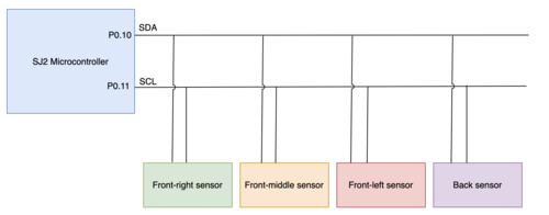
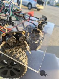
We used 4 Gravity DFRobot URM09 ultrasonic sensors. These ultrasonic sensors are used by the RC car for the purpose of obstacle avoidance. Three sensors were placed on the front side of the RC car and one on the back. They use I2C communication to send distance data to the SJ2 microcontroller. On the SJ2 microcontroller, P0.10 was used for SDA, and P0.11 was used for SCL. The measurement range is 300cm. It takes in 3.3V supply voltage. Using the I2C driver, the registers on the ultrasonic sensors were configured and the distance was read from the specified registers in the datasheet.
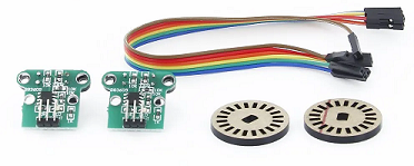
The wheel encoder is interfaced using 3 pins: VCC, GND, and OUT. The voltage input requires 4.5-5.5V and the data pin outputs 5V. The 5V output is converted to 3.3V using a level converter, and then used as a GPIO input to P0.22 on the SENSOR node.
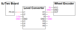
The rotary wheel has 20 slits spaced evenly. An infrared beam and sensor is used to detect when the beam is blocked. When the beam is blocked, the data OUT pin outputs 0V. When the beam is unblocked, the data OUT pin outputs 5V.
Software Design
The ultrasonic sensors use the I2C driver available in the project. The implementation is done in the 100Hz periodic callback function. After writing to the control register address of the ultrasonic sensors, the distance values are read from another register which provided the distance in a single byte. To prevent signal interference, only one sensor sends pulses for each iteration of the periodic_callback. After the distance values were read, they were sent to the driver for obstacle avoidance. The following are the functions used to configure the ultrasonic sensor by writing to the register and then reading from the register specified in the sensor datasheet over I2C:
static const uint8_t distance_low_bits_register = 0x04;
void ultrasonic__passive_measurement_mode(uint8_t slave_address) {
  const uint8_t passive_measurement_mode = 0x00;
  const uint8_t control_register = 0x07;
  i2c__write_single(I2C__2, slave_address, control_register, passive_measurement_mode);
}

uint8_t ultrasonic__single_sensor_read(uint8_t slave_address) {
  return i2c__read_single(I2C__2, slave_address, distance_low_bits_register);
}
Wheel Encoder
The wheel encoder uses a GPIO pin (P0.22). To measure the speed of rotation, we enabled GPIO interrupts by adding a gpio_isr module to dispatch GPIO interrupts to associated handler methods. On rising edges, a GPIO interrupt service routine (ISR) increments a wheel encoder rising edge counter. In the 100Hz periodic callback, the wheel encoder counter is used to calculate the measured rotations per minute (RPM). This RPM value is sent from the SENSOR node and is relayed through the DRIVER node to the MOTOR node. After sending out the RPM value, the wheel encoder rising edge counter is reset.
Technical Challenges
1. Ultrasonic sensor interference
- Since we had 3 ultrasonic sensors on the front side sending sound waves, there was interference between them. As a result, the values being read from the sensors were incorrect. The solution to this was to only read one sensor per periodic callback. In doing so we were able to obtain accurate sensor readings, but they were slower than what we needed for our obstacle avoidance logic. to counteract the slower measurements, we ended up moving the signal readings to the 100Hz callback instead, still reading one sensor per callback.
2. Ultrasonic sensor wiring not secure
- One of the issues we faced was that the sensors would not be connected properly because the RC car was constantly being moved around. A solution was to clean up the wiring and use a PCB. Also, we would use CAN Busmaster to check which sensors were not connected.
3. Wheel Encoder Debouncing
- When we hooked up the wheel encoder we didn't think about debouncing. Since the values were coming in fast enough, the motor logic hid the fact that sometimes we were getting spikes in the rising edge counter which made moving the car at slower speeds much more difficult. If we had noticed this sooner, we would have used a hardware solution and create a deboucing circuit on the PCB. Since we didn't have time to design and order another PCB, we went with a software debouce instead.
Motor Controller
Hardware Design
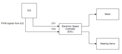
The hardware design for the motor controller was determined by the hardware of the car. We knew that the cars motors were controller through an electronic speed controller(ESC) and just had to interface the SJ2 with this. The top of the receiver revealed 12 pins, in 4 rows of 3. Each row had the following according the the sticker: GND, VCC, and signal. The signal pin would be hooked up to the pins which are firmware configured to output PWM.
Software Design
Controlling the motors was done through firmware generating PWM signals. We decided to begin by hooking up the car's receiver to a Saleae Logic Analyzer to see the waveforms generated when using the remote control that came with the car. This was helpful in many ways. First, we were able to see which channel was used for the steering servo, and which was used for the actual motor. Second, we were able to see the maximum, minimum, and neutral PWM duty cycles required and the period period of the waveform. Lastly, we were able to visually see the different sequences necessary to run the motors.
Steering Algorithm
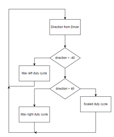
A simple algorithm was used to determine the PWM signal sent to the steering servos. We decide to have the driver node send a direction between the values of -180 to 179. After some quick testing with the values, we found the range to be much larger than then we required to get the steering to be a fluid motion. To solve this, we had our firmware treat any signal above 40 and below -40 to be max right and left respectively. We then had to scale the values within that range using the algorithm in the flow chart above.
Steering Algorithm code snippet showing the scaling duty cycle outside of the +/- 40 range sent from driver.
void motor_controller__set_direction(int16_t direction) {
  if (direction < -40) {
    motor_controller__set_direction_pwm_cycle(11.96); // 6.66
  } else if (direction > 40) {
    motor_controller__set_direction_pwm_cycle(6.66);
  } else {
    float duty_cycle = (9.31 - (direction / 40.0) * 2.65);
    motor_controller__set_direction_pwm_cycle(duty_cycle);
  }
}
Forward Backward Algorithm
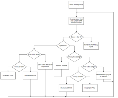
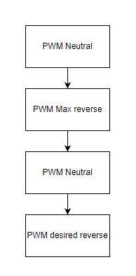
The motor speed control algorithm was more complicated due to the ESC having built in firmware to prevent the user from repeated sending forward and reverse signals and frying the motor. A specific routine was needed to allow the motor to correctly receive a reverse signal. This routine is depicted in the flow chart below. Other than that we used a fairly straight forward algorithm based on the neutral, max forward, and max reverse duty cycles read from the Saleae analyzer mentioned earlier. The driver would send a drive_speed from 0 - 31 and a current_rpm based on sensor readings. The 0 - 31 values were broken down as such:
- 0 and 5 were mapped to 'neutral' or 'idle' pwm cycles.
- 1 - 4 were varying speeds of reverse with 1 being fastest, and 4 being slowest reverse speed.
- 6 - 31 were varying speeds of forward with 6 being slowest, 31 being fastest.
The current_rpm was used to decided whether or not the car was moving at an expected speed based on a mapping which we allocated statically. From there the algorithm designed was pretty straight forward. Based on the speed and current rpm received from driver, we followed the above flow chart incrementing or decrementing the previously set PWM duty cycle as necessary. This algorithm could definitely have been improved using some basic control theory such as a PID controller, but we found that we were able to get a consistent and smooth ride speed without one.
Lookup table containing the targetted RPM for each speed sent by the driver.
static uint16_t rpm_table[] = {
    [0] = 0,    [1] = 300,  [2] = 250,  [3] = 200,  [4] = 175,  [5] = 0,    [6] = 175,  [7] = 200,
    [8] = 225,  [9] = 250,  [10] = 275, [11] = 300, [12] = 325, [13] = 350, [14] = 375, [15] = 400,
    [16] = 425, [17] = 450, [18] = 475, [19] = 500, [20] = 525, [21] = 550, [22] = 575, [23] = 600,
    [24] = 625, [25] = 650, [26] = 675, [27] = 700, [28] = 725, [29] = 750, [30] = 775, [31] = 800,
};
Flow chart explaining the reverse routine followed to enter a reverse state.
Technical Challenges
- Initial run through of the algorithm to control speed ended up 'sling-shotting' the car. This due to the PWM duty cycles being set would over shoot the desired RPM values by a large margin. To solve this, we changed the the value we scale up or down the PWM to 0.005f. Since our motor commands were being processed so quickly, a small value was needed to prevent the car from the 'sling-shotting' behavior of ramping up and down the motor to quickly.
- The reverse routine and start up routines of the motor may vary depending on the firmware that comes along with the ESC. For Traxxas, a specific routine was needed to start and reverse the motors. Without a logic analyzer or oscilloscope to visualize the routine, deciphering it would have been near impossible.
- Start off slow and then ramp up after. It really does not take much higher than the neutral duty cycle to make the cars move at a decent pace. Early on, we capped our speed to 300rpm and this would have been plenty fast enough to even get through the demo.
Geographical Controller
Code for GEO Node
Code for LSM303 Compass
GPS module
Compass and Accelerometer
Hardware Design
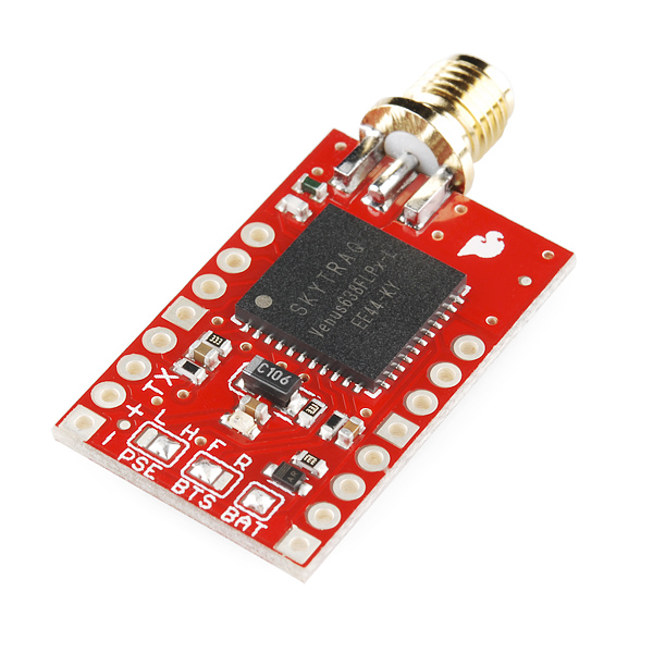
SparkFun Venus GPS with SMA Connector
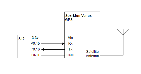
For the GPS location, we used the SparkFun Venus GPS. The GPS module was interfaced using UART protocol with a baud rate of 9600 bps. The module was interfaced with an NMEA command to output GPGGA messages to the autonomous car.
LSM303DLHC Magnetometer
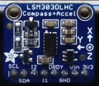
For the compass heading we used the lsm303DLHC compass + accelerometer from Adafruit. The compass was interfaced using I2C with a speed of 100KHz. The data output rate was set to 220HZ. The gain was left as the default +-1.3 gauss. The operation mode was switch to continuous conversion mode. The compass was placed at a safe distance above all of the other hardware components to minimize the magnetic disturbance.
Software Design
GPS Coordinate Message Parsing
The GPS module will output several UART messages containing geological location information. We set the message type to GPGGA format using the NMEA command provided by the documentation of the GPS module. The message string was parsed using the "strtok" function and hashed using the "atof" function to turn each part of the string into float values that the care can use.
Setting the NMEA command was done using the following function:
void gps_config__init_nmea_gpgga(void) {
  uint8_t message_data[100] = {0xA0, 0xA1, 0};
  uint8_t cs = 8;
  uint16_t length = 9;
  message_data[5] = 1;
  message_data[6] = 0;
  message_data[7] = 0;
  message_data[8] = 0;
  message_data[9] = 0;
  message_data[10] = 0;
  message_data[11] = 0;
  message_data[12] = 0;
  for (int index = 5; index < length + 4; index++) {
    cs = cs ^ message_data[index];
  }
  message_data[2] = length / 256;
  message_data[3] = length % 256;
  message_data[4] = 8;
  message_data[4 + length] = cs;
  message_data[5 + length] = 0x0D;
  message_data[6 + length] = 0x0A;

  for (int i = 0; i < 7 + length; i++) {
    uart__polled_put(UART__1, message_data[i]);
  }
}
An example of parsing and hashing the string:
static char *token;
const char *delim = ",";

token = strtok(gps_final_string, delim);
// get time
token = strtok(NULL, delim);
if (token != NULL)
  time = atof(token);
A GPGGA message appears as follows:
Message Format:
$GPGGA,HHMMSS.SS,DDMM.MMMMM,K,DDDMM.MMMMM,L,N,QQ,PP.P,AAAA.AA,M,±XX.XX,M, SSS,RRRR*CC<CR><LF>
| Message Component | Description |
|---|---|
| $GPGGA | Message type indicator |
| HHMMSS.SS | UTC time in hours, minutes, and seconds of the position |
| DDMM.MMMMM | Latitude in degrees, minutes, and decimal minutes |
| K | Latitude indicator; value is N (North latitude) or S (South latitude) |
| DDDMM.MMMMM | Longitude in degrees, minutes, and decimal minutes |
| L | Longitude indicator; value is E (East longitude) or W (West longitude) |
| N | Quality indicator (indicates positional lock) |
| Number of satellites used in position solution | |
| PP | Horizontal dilution of precision (HDOP) |
| A.A | Antenna altitude, in meters, re: mean-sea-level (geoid) |
| M | Units of antenna altitude (M = meters) |
| G.G | Geoidal separation (in meters) |
| M | Units of geoidal separation (M = meters) |
| SSS | Age of differential corrections, in seconds |
| RRRR | Differential reference station ID |
| *CC | Checksum |
| <CR> | Checksum |
| <LF> | Carriage return |
Compass Implementation and Calibration
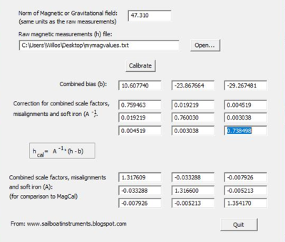
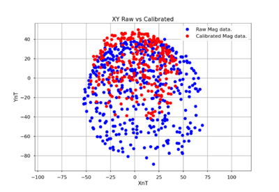
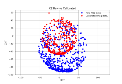
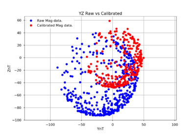
Once the required registers have been initialized, the compass will return uncalibrated x, y, and z values. For its calibration we used the software Magneto v1.2. Magneto requires a txt file of raw magnetometer values and our locations magnetic field. Magneto will then provide the bias and scaling factor matrix needed for calibration. Those values are then plug into the equation in the code below, where gain is 1100 gauss for the x and y values and 980 gauss for the z value. Those calibrated x and y values are used to find the radians of the compass heading. The radians are then converted and returned as degrees. By flipping the compass upside down, the compass was able to reduced tilt factor to provide accurate readings.
double calibrated_vales(lsm303_compass__data_s compass_data) {

  float X_offset, Y_offset, Z_offset;

 /**calibration data for 36.6777° N, 121.6555° W**/
  X_offset = (compass_data.x / 1100.00 * 100) - 10.607740; // axis raw value divided by gauss value - bias
  Y_offset = (compass_data.y / 1100.00 * 100) + 23.867664; //
  Z_offset = (compass_data.z / 980.0 * 100) + 29.267481;   // Z-axis has a different gauss value

  X_offset = 0.759463 * X_offset + 0.019219 * Y_offset + 0.004519 * Z_offset; // value of 3x3 matrix from magneto
  Y_offset = 0.019219 * X_offset + 0.760030 * Y_offset + 0.003038 * Z_offset; //
  Z_offset = 0.004519 * X_offset + 0.003038 * Y_offset + 0.738498 * Z_offset; //


  return atan2(X_offset, Y_offset) * 180 / M_PI;
}
Magneto1.2v Calibration
Coordinate Calculations
Distances between two locations is calculated using two coordinate locations. This is used to give the Driver node distance to destination. This is also used for the Geo node to calculate if it has arrived at its current destination node.
sqrt[(latitude 2 - latitude 1)^2 + (longitude 2 - longitude 1)^2]
Angular Heading with respect to north is calculated using two coordinate locations. This is used to get the destination heading angle from the car's current location to the current destination.
arctan[(latitude 2 - latitude 1) / (longitude 2 - longitude 1)] * (180/pi)
Some adjustments had to be made to the value to stay within the 0-360 degree range we wanted.
// adjust for negative longitude
 if (long_difference < 0) {
   heading += 180.0;
 }
 // adjust for negative angle
 if (heading < 0) {
   heading += 360.0;
 }
Waypoints Algorithm
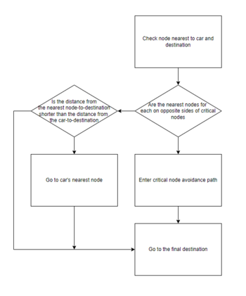
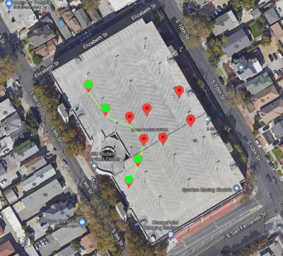
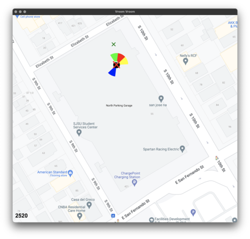
The waypoints algorithm was made to avoid the large roundabout on the center-right of the parking garage. This is because the car cannot use object avoidance to sense and avoid the down and up ramps of the roundabout. When traveling around the parking garage, if the distance from the car's closest waypoint to the final destination is less than the distance from the car's location to the final destination; the car will set the waypoint as its current destination. This behavior simplifies to going to the waypoint if it is in between the car and final destination. There is extra logic included to avoid the roundabout that we labeled as critical nodes and critical paths. The critical nodes are indicated with the green mark. The critical path is indicated with the yellow lines. If the car's current closest node is a critical node and the final destination's closest node is a critical node on the opposite side of the roundabout, the car will travel the critical path. This allows the car to avoid that large obstacle.
Traversing the critical path was done with the following formula:
current_critical_node = current_location_closest_waypoint_index;
final_critical_node = final_destination_closest_waypoint_index;

if (critical_path_flag) {
  // have not arrived at next critical node
  if (!coordinate_calculation__arrived(current_location.latitude, current_location.longitude,
                                       waypoints[current_critical_node].latitude,
                                       waypoints[current_critical_node].longitude)) {
    return waypoints[current_critical_node];
  }
  // have arrived at critical node, return next node
  else {
    if (current_critical_node > final_critical_node) {
      current_critical_node--;
      return waypoints[current_critical_node];
    } else if (current_critical_node < final_critical_node) {
      current_critical_node++;
      return waypoints[current_critical_node];
    }
    // arrived at last critical node, continue to final destination
    else {
      critical_path_flag = false;
      return final_destination;
    }
  }
}
Haversine Formula for Distance
To calculate the distance between the current latitude and longitude of the RC car and the destination latitude and longitude the haversine formula was used rather than the pythagorean theorem to calculate the shortest distance in meters. The latitude and longitude had to be converted from degrees to radians and the haversine distance was calculated by finding the difference between them and then performing trigonometric operations to find the haversine angle. From this the distance is calculated and returned to the driver node.
static float calculate_distance_in_meters(void) {
  const float radius_of_earth_km = 6378.137;
  float destination_latitude_radians = convert_degrees_to_radians(geo_current_destination.latitude);
  float current_latitude_radians = convert_degrees_to_radians(curr_latitude);
  float latitude_difference = destination_latitude_radians - current_latitude_radians;

  float longitude_difference = (geo_current_destination.longitude - curr_longitude) * (M_PI / 180);

  float haversine_angle = pow(sinf(latitude_difference / 2), 2) + cosf(current_latitude_radians) *
                                                                      cosf(destination_latitude_radians) *
                                                                      pow(sinf(longitude_difference / 2), 2);
  float distance = 2 * atan2f(sqrt(haversine_angle), sqrt(1 - haversine_angle));
  float distance_in_meters = radius_of_earth_km * distance * 1000;
  return distance_in_meters;
}
Technical Challenges
1. Compass calibration
We had to continuously calibrate the compass to get as accurate of a reading as we could get for our demos. If the compass was not properly calibrated, we would see "dead spots" in the compass heading where the degree angle would shift rapidly so as to give inaccurate readings.
To solve this, we:
- Use magnetic field of current position
- Use Magneto software
2. Reliable compass readings
Our compass was not 100% accurate and reliable so we had to adjust the environment to best suit the compass. This let us get very close to 100% accurate readings.
To solve this, we:
- Flip the compass upside down for more accurate tilt compensation readings
- Place compass at a high enough distance to reduce interference
3. Waypoints algorithms
We had to use waypoints to avoid the giant obstacle that obstacle avoidance could not handle. However, there were several different approaches we could have taken. The biggest consideration was that we wanted to have low computation time. This meant we could not use Dijkstra's shortest path algorithm to traverse nodes since that would take a lot of processing time. If we used a simple "always go to waypoint" formula, that would look silly as well.
To solve this, we:
- Created a distance based algorithm so the car will travel to "convenient" nodes
- Forced a critical path whenever the car needed to avoid the large obstacle
Driver Controller
Code for Driver Logic Debug Menu State Machine for Menu Navigation
Code for LCD I2C Initialization and Configuration
Code for LED Ring Implementation

Hardware Design
LED Ring
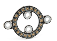
The LED ring we are using is a LuMini LED ring from Sparkfun. It is composed of 20 LEDs and requires a voltage input of 5 volts, a clock signal, and data signal. For communicating with the SJ2, we used the SPI protocol. The led ring works like an array with the first led position at 0 and the last at position 19. The communication protocol requires 32 bits, all set to 0 as the starting frame. Once the starting frame has been set, all the 20 LEDs need to be set to either on or off. Each LED follows the same 32-bit communication format. The first 8 bits are the starting bits plus the brightness. The next 24 bits determine the colors of the LEDs using the RGB color scale. Finally, there is an ending frame of all 32 bits set to 1.
LCD Hardware
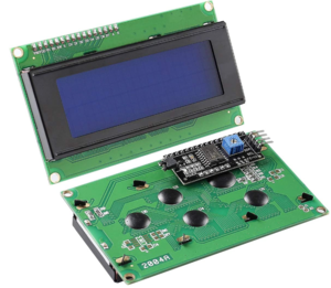
For the LCD we are using a 20x4 I2C LCD2004. The LCD uses a separated I2C interface board composed of an 8 bit I/O expander for I2C bus. It required a voltage input of 5v and an I2C slave address 0x4E. The clock speed was set to 100kHZ. The i2c data transferred was different from the usual. There was no sub addressed or registers, instead normal communication will behave as following: slave address, data 1, and data2.
Software Design
Inside periodic_callbacks_DRIVER.c, driver_logic__manage_debug_menu_10hz is periodically called at 10Hz rate. The definition for this method is shown below:
 void driver_logic__manage_debug_menu_10hz(uint32_t callback_count) {
   display_debug_menu_on_lcd(callback_count);
   handle_debug_menu_navigation();
 }
This snippet of code is responsible for maintaining the LCD debug menu state machine. It periodically updates the LCD to display menu navigation screens or debug information.
LED Ring State Machine
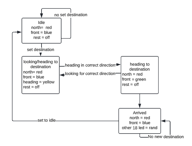
The LED ring was set for debugging and presentation purposes. At all times it will display the direction of the compass in blue and true north with red. Once a location has been set, a yellow LED will appear to indicate where the car should head. If the car is heading in the correct direction the yellow LED and blue LED will then turn green. Finally, when the car arrives at the set destination or at a waypoint, the led ring will make every light blink with different colors. All major indicators will be on at the same time, even when the car has arrived at its destination. Even when all LEDs are blinking at a final destination, north and front will not change colors and their brightness will increase for better visibility.
The following are code snippets for the data frames sent to the LED ring. The data frame consists of starting and ending frames and a data frame for setting the color and its intesity:
// starting frame all 32 bits 0
void led_ring_starting_frame(void) {
  ssp2__exchange_byte(0x00);
  ssp2__exchange_byte(0x00);
  ssp2__exchange_byte(0x00);
  ssp2__exchange_byte(0x00);
}
// ending frame first 10 bits 0 the rest
void led_ring_ending_frame(void) {
  ssp2__exchange_byte(0xFF);
  ssp2__exchange_byte(0xFF);
  ssp2__exchange_byte(0xFF);
  ssp2__exchange_byte(0xFF);
}
void led_ring_all_on(uint8_t brightness, uint8_t blue, uint8_t green, uint8_t red) {
  for (int f = 0; f < 20; f++) {
    ssp2__exchange_byte(brightness);
    ssp2__exchange_byte(blue);
    ssp2__exchange_byte(green);
    ssp2__exchange_byte(red);
    delay__us(10);
  }
}
LCD Implementation
The LCD needed to be set to 4-bit mode with specific delays, enables and functionality. The LCD data is set in two formats. One is for displaying characters on the screen using ASCII. The hex ASCII value is sent 4 times. Each time is sent, the first four bits are based on the ASCII hex value. For example, 'a' is 0x1C, therefore the first four bits for the first two writes will be 0x1 and the other two will be 0xC. The other four bits are for setting brightness, enable, r/w, and select. The other format is command send, which is for implementation purposes, or location setting. It follows the same methodology as sending characters, but the select is off for all four transmissions. To write to the display, we would need to send a command to set the location of the message. Then we need to send the actual data as a string. If it is a short string, the rest of the pixels need to be set to empty spaces. This is necessary to display values that are constantly being updated. If not set, the LCD would display old characters. This is call at 100Hz in periodic callbacks.
void i2c_lcd__send_command(char command) {

  uint8_t cmd_w[4];
  cmd_w[0] = (command & 0xf0) | 0x0C;
  cmd_w[1] = (command & 0xf0) | 0x08;
  cmd_w[2] = ((command << 4) & 0xf0) | 0x0C;
  cmd_w[3] = ((command << 4) & 0xf0) | 0x08;
  i2c__write_single(i2c_lcd__sensor_bus, i2c_lcd__address, cmd_w[0], cmd_w[1]);
  i2c__write_single(i2c_lcd__sensor_bus, i2c_lcd__address, cmd_w[2], cmd_w[3]);
}

void i2c_lcd__send_data(char data) {

  uint8_t data_w[4];
  data_w[0] = (data & 0xf0) | 0x0D;
  data_w[1] = (data & 0xf0) | 0x09;
  data_w[2] = ((data << 4) & 0xf0) | 0x0D;
  data_w[3] = ((data << 4) & 0xf0) | 0x09;

  i2c__write_single(i2c_lcd__sensor_bus, i2c_lcd__address, data_w[0], data_w[1]);
  i2c__write_single(i2c_lcd__sensor_bus, i2c_lcd__address, data_w[2], data_w[3]);
}
Drive Logic
Overall Design
The above flowchart shows the high level overview of our driver logic which begins with receiving sensor values from the sensor controller. The first check is to see if we are currently idle or not. This is the one check that will override all others, including emergency stop thresholds. We decided on this design since there are no real breaks for the car, we wanted to be able to steer as the car is coming to a stop. Emergency stop is handled in a different routine, thus we had to make this check first to obtain the desired functionality. If the car is not in the idle state, then we next check the sensor values to see if any are within the emergency stop threshold which we set to 30cm or 1 foot. If any of the readings indicated this, then we went to the emergency stop routine, described below. If the sensor readings all read above the emergency stop threshold, then we check to see if there is an obstacle within our next threshold. The threshold to detect an obstacle is 140cm. This value was chosen because of the sensor configuration giving most accurate values up to this distance. When an obstacle is detected, we perform a deflection calculation which would give us a linear mapping of how much to change the steering angle depending on how far away it was from the car. The closer the obstacle, the harsher the steering angle we would send. If no obstacle was in the threshold value, then we simply sent the same steering that was calculated according to our destination and current heading. The correlation between deflection/motor speed and obstacle distance is illustrated in the diagram below.
Emergency Stop
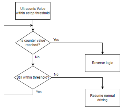
Emergency stop was handled as a special case of object detection. If an object entered the threshold for an emergency stop (30cm), then we send an idle speed to the motors and start a timer in which we monitor the sensor values. If at the end of the timer (timer is just a counter based on callback count) one or more of the ultra sonic sensors are still detecting an object within the emergency stop threshold, then we enter the reverse routine below.
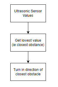
Reverse Logic
Reverse logic was needed in the case that the car stayed within the emergency stop threshold of an object for a preset amount of callbacks. If this was the case, we would reverse in the same direction of the sensor with the lowest distance reading. The logic behind this was that we wanted to head in a direction which way away from the object that got us stuck in the first place. IE if the right most sensor was within the emergency stop threshold, we would reverse back and to the right so that the car would face in a more leftward direction away from the obstacle.
static int16_t obstacle_avoid_direction_when_reversing(dbc_SENSOR_TO_DRIVER_SONARS_s *sense) {
  uint8_t lowest_value = lowest_sensor_reading(sense);
  if (lowest_value == sense->SENSOR_TO_DRIVER_SONARS_front_middle) {
    return 0;
  } else if (lowest_value == sense->SENSOR_TO_DRIVER_SONARS_front_right) {
    return 90;
  } else {
    return -90;
  }
}
Technical Challenges
1. LCD display is limited to 4 lines of 20 characters. Having this limit creates a challenge for efficiently using the screen for debugging.
- To resolve this issue, we designed and implemented a finite state machine to update the LCD display according to a debug menu state. This solution is beneficial for its scalability. New debug information can be easily included as additional options in the menu navigation.
2. I2C bus speed was configured too high
- We saw issues with the LCD screen resetting unexpectedly during testing. This was due to our I2C bus speed being configured to run at 400KHz. After reviewing the datasheet, we found that using 100KHz for the I2C bus speed is the correct configuration.
3. Compass heading does not display true north
- After comparing the compass heading with a premade compass, it showed the both compasses rotated in different directions. True north will only be real when compass heading was 0. For all other cases, true north needed to be set at the opposite direction. For example, if compass heading is showing 45 degrees, true north would be 270 degrees.
Remote Application
Hardware Design
The hardware used for the application implementation consisted of an SJTwo with an ESP8266, a laptop hosting a Python application, and a mobile hotspot acting as a WiFi hub. When the phone was configured as a mobile hotspot, both the the laptop and the SJTwo would connect with static IP addresses to begin communication.
Software Design
Both a UDP server and client were established on both the laptop (using a Python script for handling network sockets and data visualization) and on the SJTwo through C boilerplate code for the ESP8266. The app would send user-specified GPS coordinates by having the user click a location on the displayed map, and the SJTwo would send debug information from the vehicle.
Firmware Implementation
The ESP client and server on the SJTwo were serviced using a dedicated RTOS task. The task would periodically monitor for a continuously-transmitted GPS destination UDP message from the app, while a formatted string containing each individual data field to utilize in the app was repeatedly sent as a UDP message.
snprintf(buffer, sizeof(buffer), "%f,%f,%i,%i,%f,%i,%i,%i,%i,%i,%f,%f\r\n", loc.GEO_CURRENT_LOCATION_DEBUG_latitude,
         loc.GEO_CURRENT_LOCATION_DEBUG_longitude, rot.GEO_STATUS_compass_heading,
         rot.GEO_STATUS_destination_heading, rot.GEO_STATUS_distance_to_destination,
         rpm.SENSOR_TO_DRIVER_WHEEL_ENCODER_MSG_rpm, sensor_data.SENSOR_TO_DRIVER_SONARS_front_left,
         sensor_data.SENSOR_TO_DRIVER_SONARS_front_middle, sensor_data.SENSOR_TO_DRIVER_SONARS_front_right,
         sensor_data.SENSOR_TO_DRIVER_SONARS_back, dest.GEO_CURRENT_DESTINATION_LOCATION_DEBUG_latitude,
         dest.GEO_CURRENT_DESTINATION_LOCATION_DEBUG_longitude);
App Implementation
The laptop application was created using a Python script with the built-in sockets library for UDP server/client communication and the tkinter package for the UI.
Technical Challenges
A function for translating the received ASCII-encoded latitude and longitude values to floats (atof) was not producing valid results with the given compiler and build settings. Shallow research into the problem revealed that this may have been caused by the compiler flag "-mfloat-abi=hard" triggering inclusion of an invalid float conversion subroutine. To get around this problem, a custom string-to-float conversion function was written.
static float string_to_float(char *input_string) {
  bool negative = false;
  size_t end_of_integer = 0;
  int64_t running_integer = 0;
  size_t curr_char_index = 0;
  while (true) {
    char curr_char = input_string[curr_char_index];
    if (curr_char == '\0') {
      break;
    } else if (curr_char == '-') {
      negative = true;
    } else if (curr_char == '.') {
      end_of_integer = curr_char_index;
    } else {
      running_integer = (running_integer * 10) + (curr_char - '0');
    }
    curr_char_index++;
  }
  return (negative ? -1.0 : 1.0) * running_integer / (pow(10, (curr_char_index - end_of_integer - 1)));
}
Conclusion
Overall this project taught us many industry relevant topics. We were able to utilize and understand the CAN Bus to create a realistic self-driving RC car which emulated how a real car would function. Different controllers were used for: obtaining geological and position related data, obtain RPM and distance data through various sensors, control steering servo and control forward/ reverse speed, and a singular driver controller to control logic.
Some of the key take-aways and learnings from this project:
- Working with a team is not always easy. Having defined goals for each person to complete is important. LIST THEM OUT, don't just say what each person will do.
- Testing location matters. The performance of our vehicle improved greatly once we moved outdoors.
- CAN Bus is robust, definitely more so than our software and hardware implementations. Never was the root cause of an issue CAN bus. It was always root caused as something we did or designed.
Project Video
Youtube Link <-- temporary video, will be updated
Project Source Code
Advice for Future Students
- Add a mobile kill-switch to stop the car
- The car may drive at high speeds and not behave as expected. It is helpful to be able to wirelessly stop the car.
- Add plenty of LED indicators on the RC car
- GPS lock, app connection, obstacle detection, destination reached, etc
- Turn off on-board LEDs for each controller at the end of periodic_callbacks__initialize(). The current base code will light the on-board LEDs in peripherals_init(). By turning off the LEDs after initialization, it will be convenient to use the LEDs to indicate whether the board is resetting unexpectedly
- Stabilize your compass readings
- Calibrate your compass
- Verify tilting the car will not drastically affect magnetometer readings
- Mount the compass module away from metals and any hard/soft iron that may cause the readings to be inaccurate
- Unit test code modules to verify expected behavior
- Once your car can move, test outside on the garage.
- Ultrasonic sensors give incorrect readings at steep angles, making testing in the hallway somewhat difficult.
- Compass readings are also more accurate outside the building where there is less interference.
- Lastly and most importantly, trust yourselves. This project is daunting, but Preet has laid it out in a way that gives you little milestones that come together to a complete project.
Acknowledgement
We would like to acknowledge our instructor, Preet, for encouraging us to gather knowledge and to tackle difficult problems. We would also like to thank him for sharing his industry experience and providing us with a class and project that will be beneficial for us and our success in the industry going forward.
References
1. Ultrasonic Sensor Project Wiki
2. GPGGA Message Definition
3. LSM303DLHC Datasheet
4. Calibration Implementaion
5. Venus638FLPx GPS Receiver Datasheet
6. LCD Datasheet
7. LCD Display Initialization and Configuration Example Tutorial
8. LCD Display Implementation and Flowchart Tutorial
9. APA102 Ring LED Datasheet
10. Logic Level Converter Datasheet
