Difference between revisions of "S14: Asset Management and Location System"
Proj user7 (talk | contribs) (→Tile Device) |
(→GitLab) |
||
| (86 intermediate revisions by one other user not shown) | |||
| Line 1: | Line 1: | ||
| + | <!-- | ||
=== Grading Criteria === | === Grading Criteria === | ||
<font color="green"> | <font color="green"> | ||
| Line 10: | Line 11: | ||
** Quality of technical challenges and solutions adopted. | ** Quality of technical challenges and solutions adopted. | ||
</font> | </font> | ||
| + | --> | ||
== S14: Asset Management and Location System == | == S14: Asset Management and Location System == | ||
== Abstract == | == Abstract == | ||
| − | The ultimate vision of this project | + | The ultimate vision of this project was to develop an asset management and location system to |
| − | compete with [http://www.thetileapp.com/ The Tile App]. There | + | compete with [http://www.thetileapp.com/ The Tile App]. There were two major components to the Tile solution: the tile and |
| − | the application. The | + | the application. The tile was small low-power embedded system that could be attached to an object. The |
| − | application | + | application was primarily a user interface that provides visual feedback to guide a user to a specified tag. |
| + | |||
| + | For this project, the tile is simply a Bluetooth module powered by a coin cell battery. The management unit, on the other hand, consists of: | ||
| + | # SJ One development board | ||
| + | # LCD | ||
| + | # Bluetooth module | ||
| + | # GPS module | ||
| + | |||
| + | The system used the Bluetooth RSSI value to determine proximity of the application device to the tile device. SJ One board communicated proximity to the user via a histogram that was displayed on the LCD. If the tile device was within the expected proximity, the GPS coordinates of the tile device were written to a file on the SC card. A webpage was developed which would read this file and plot the tile location of know tiles on Google Maps. | ||
| + | |||
| + | Complete feature set of Asset Management and Location System enabled the following: | ||
| + | # Locating/tracking a tile | ||
| + | # Adding/registering a new tile | ||
| + | # Removing a tile | ||
| + | # Listing all the registered tiles | ||
| + | # Updating the RTC | ||
| + | # Displaying the last known location of tiles on Google Maps | ||
== Objectives & Introduction == | == Objectives & Introduction == | ||
| Line 28: | Line 46: | ||
* To add/register tiles to user | * To add/register tiles to user | ||
* To remove tiles from user tiles database | * To remove tiles from user tiles database | ||
| − | * | + | * To display a histogram of tile vicinity |
| − | * | + | * To display last known location on Google Maps |
=== Team Members & Responsibilities === | === Team Members & Responsibilities === | ||
| − | * Akash Ayare | + | * Akash Ayare - Feature development |
| − | * Pardeep Badhan | + | * Pardeep Badhan - Feature development |
| − | * Talha Ilyas | + | * Talha Ilyas - Packaging and feature unit testing |
== Schedule == | == Schedule == | ||
| Line 98: | Line 116: | ||
! scope="row"| 9 | ! scope="row"| 9 | ||
| 5/1 | | 5/1 | ||
| − | | Packaging, battery installation, and testing. Expansion of feature-set | + | | Packaging, battery installation, and testing. Expansion of feature-set. |
| Enhanced features: | | Enhanced features: | ||
# Added CharDev pointers in LCD and Bluetooth class instead of using the Uart2 and Uart3 directly. This allowed us to switch Uart ports with minimum code changes | # Added CharDev pointers in LCD and Bluetooth class instead of using the Uart2 and Uart3 directly. This allowed us to switch Uart ports with minimum code changes | ||
| Line 124: | Line 142: | ||
# trackTile... function has been refactored to maintain historical behavior, but now invokes inquirySingleBTDevice API. The inquiryAllBTDevices function signature was modified to include an optional argument to display the "Searching..." message. This message is not desirable when displaying a histogram in a loop. In any case, the inquiryAllBTDevices API remains backward compatible. Note: In testing, unexpected behavior was observed when a tile comes into or exits the field of vision while in trackingMode. | # trackTile... function has been refactored to maintain historical behavior, but now invokes inquirySingleBTDevice API. The inquiryAllBTDevices function signature was modified to include an optional argument to display the "Searching..." message. This message is not desirable when displaying a histogram in a loop. In any case, the inquiryAllBTDevices API remains backward compatible. Note: In testing, unexpected behavior was observed when a tile comes into or exits the field of vision while in trackingMode. | ||
|- | |- | ||
| − | ! scope="row" | | + | ! scope="row" | 11 |
| 5/15 | | 5/15 | ||
| − | | | + | | Final Exams, Additional week for bug fixing, testing, and packaging. |
| Fixed bugs: | | Fixed bugs: | ||
# Bluetooth inquiry wasn't terminating when no devices were found. The state machine was going into PENDING_DEVICES state. | # Bluetooth inquiry wasn't terminating when no devices were found. The state machine was going into PENDING_DEVICES state. | ||
| Line 137: | Line 155: | ||
# Adding "Time" menu. With this menu, the user can view and set the time. Time is displayed in the following format: MM/DD/YYYY HH:MM This menu operates in the following way: | # Adding "Time" menu. With this menu, the user can view and set the time. Time is displayed in the following format: MM/DD/YYYY HH:MM This menu operates in the following way: | ||
## After changing to Time menu, if the user clicks "Back", the main menu is displayed, and if the user clicks "Select", the user is allowed to change the time - the user is in "change time" state. | ## After changing to Time menu, if the user clicks "Back", the main menu is displayed, and if the user clicks "Select", the user is allowed to change the time - the user is in "change time" state. | ||
| − | ## If in "change time" state, the user can cycle back and forth between month, day, year, hour, and minute. If the user cycles through all of these, the time is updated. If the user cycles backwards, the time is not updated. Caret character (^) guides the user when in "change time" state. | + | ## If in "change time" state, the user can cycle back and forth between month, day, year, hour, and minute. If the user cycles through all of these, the time is updated. If the user cycles backwards, the time is not updated. Caret character (^) guides the user when in "change time" state. |
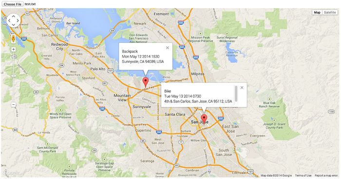
| + | # Added support for Google Maps. After opening the webpage, browse and select a file that contains information about the tile. The webpage will parse the file and display the location of each tile. Hovering over the marker will display the tile name, and clicking on the tile will display the 1) tile name, 2) time (last known instance), 3) last known location. | ||
|- | |- | ||
| − | ! scope="row" | | + | ! scope="row" | 12 |
| 5/22 | | 5/22 | ||
| − | | | + | |Demo and report submission. |
| More feature development: | | More feature development: | ||
# Enabled UART1 support | # Enabled UART1 support | ||
# Enabled GPS support. Fetched GPS data using UART2, parsed the fetched GPS data, and updated the global variable. | # Enabled GPS support. Fetched GPS data using UART2, parsed the fetched GPS data, and updated the global variable. | ||
| + | # Added a Map task which will periodically (every 30 seconds) generate the gpsmap.txt file, but only if there is a file in the gpsdb/ directory that has a timestamp which is greater than gpsmap.txt; otherwise, the map task simply returns with minimal execution. The only time files are added to the gpsdb/ directory is when an attempt to track a file is made and the tile is found within a close range. At that moment, by hitting the back switch GPS data for that tile will automatically be recorded. Currently, GPS records do not get deleted when a tile is deleted. | ||
|} | |} | ||
| Line 182: | Line 202: | ||
| $24.95 | | $24.95 | ||
| 1 | | 1 | ||
| − | + | | $299.80 | |
| + | |- | ||
| + | ! 5 | ||
| + | | [https://www.sparkfun.com/products/retired/9171 Venus GPS Logger with SMA Connector] | ||
| + | | $59.95 | ||
| + | | 1 | ||
| + | | $359.75 | ||
| + | |- | ||
| + | ! 6 | ||
| + | | [https://www.sparkfun.com/products/177 Antenna GPS Embedded SMA] | ||
| + | | $11.95 | ||
| + | | 1 | ||
| + | | $371.70 | ||
| + | |- | ||
| + | ! 7 | ||
| + | | [http://www.frys.com/product/7824419?site=sr:SEARCH:MAIN_RSLT_PG Philmore Micro Rocker Switch] | ||
| + | | $1.99 | ||
| + | | 1 | ||
| + | | $373.69 | ||
| + | |- | ||
| + | ! 8 | ||
| + | | [http://www.radioshack.com/product/index.jsp?productId=2062492 SPDT Sub-Mini Slide Switch 2-Pack] | ||
| + | | $3.99 | ||
| + | | 1 | ||
| + | | $377.68 | ||
| + | |- | ||
| + | ! 9 | ||
| + | | Tile Enclosure | ||
| + | | $0.98 | ||
| + | | 2 | ||
| + | | $379.64 | ||
| + | |- | ||
| + | ! 10 | ||
| + | | Tracker Enclosure | ||
| + | | $4.99 (+ $11.99 fabrication) | ||
| + | | 1 | ||
| + | | $396.62 | ||
| + | |- | ||
| + | ! 10 | ||
| + | | 9V Battery | ||
| + | | $4.99 | ||
| + | | 2 | ||
| + | | $406.60 | ||
| + | |- | ||
| + | ! 11 | ||
| + | | [http://www.frys.com/product/2966375?site=sr:SEARCH:MAIN_RSLT_PG Philmore 9V Snap-In Battery Holder] | ||
| + | | $0.89 | ||
| + | | 1 | ||
| + | | $407.49 | ||
| + | |- | ||
| + | ! 12 | ||
| + | | [https://www.sparkfun.com/products/12624 24.5mm Coin Cell Battery] | ||
| + | | $2.95 | ||
| + | | 2 | ||
| + | | $413.39 | ||
| + | |- | ||
| + | ! 13 | ||
| + | | 12mm Coin Cell Battery | ||
| + | | $1.99 | ||
| + | | 1 | ||
| + | | $415.38 | ||
| + | |- | ||
| + | ! 14 | ||
| + | | Fabricated Button Extensions | ||
| + | | $0.99 | ||
| + | | 1 | ||
| + | | $416.37 | ||
| + | |- | ||
| + | ! 15 | ||
| + | | Micro SD Card | ||
| + | | $9.99 | ||
| + | | 1 | ||
| + | ! $426.36 (tax + shipping not included) | ||
|} | |} | ||
== Design & Implementation == | == Design & Implementation == | ||
| − | The design section can go over your hardware and software design. Organize this section using sub-sections that go over your design and implementation. | + | <!--The design section can go over your hardware and software design. Organize this section using sub-sections that go over your design and implementation.--> |
| + | |||
| + | === Components === | ||
| + | =====LPC1758 SJSU One Development Board===== | ||
| + | |||
| + | The SJSU One Development Board serves as the management system behind the functionality of the Tracker device. The utilization of the hardware (primarily UART interfaces) along with the strengths of FreeRTOS for task scheduling capabilities provide for a solid foundation for the Tracker's proposed features. The SJSU One Board is intergrated with Bluetooth, LCD, and GPS peripheral devices. Power is supplied to the peripheral devices by the SJSU One Board. The Bluetooth module TX and RX are interfaced with the SJSU One Board's UART3 for command issuance/execution and data parsing capabilities. The LCD and GPS modules are interfaced with UART2 of the SJSU One Board in order for appropriate display output and Google Map functionality integration, respectively. | ||
| + | |||
| + | =====Power Supplies===== | ||
| + | |||
| + | The Tracker device is powered by a 9V battery circuit with a micro rocker switch, which in-turn indirectly power the Tracker's peripheral devices through the SJSU One Board. The Tile module is powered by a 3.6V 24.5mm coin cell battery inline with a slider switch (to maximize battery life during development and testing) which is connected to a Bluetooth module. | ||
| + | |||
| + | =====Bluetooth Mate/BlueSMiRF Gold===== | ||
| + | |||
| + | The Bluetooth module is interfaced to UART 3 for the Tracker system and provides for communications between the user and the Bluetooth module. In detail, it allows for the user commands to be input through the push-buttons and the corresponding software serially communicates the appropriate commands and actions to the Bluetooth module. The Bluetooth module within the Tile device is simply powered by a battery and only communicates to other devices (i.e. Tracker) through the Bluetooth protocol. The Bluetooth module in the Tracker utilizes Bluetooth to communicate with all potential Tiles and Bluetooth devices wirelessly through the Bluetooth protocol, but provides serial I/O to the SJSU One Board via UART. | ||
| + | |||
| + | =====Serial Enabled 16x2 LCD===== | ||
| + | |||
| + | The LCD module is interfaced to UART2 TX on the SJSU One Board in order to provide the user a menu-based interface to select certain actions for the Tracker to deploy and for feedback/stored information. The LCD in conjunction with the on-board push-buttons allow for the user to fully realize Tracker features (i.e. Add, Remove, Track, and List Tiles, among other functionality. | ||
| + | |||
| + | =====Venus GPS Logger with SMA Connector===== | ||
| + | |||
| + | The GPS module is interfaced with UART2 RX on the SJSU One Board in order to provide location based data information the the SJSU One Board whenever a signal is available (used in conjunction with the Antenna GPS Embedded SMA). The GPS contains data-logging capabilities and can store to the Micro SD Flash Memory Card whenever the (via application code) whenever signal is established. The data can then be used from the memory card to view locations in Google Maps. | ||
=== Hardware Design === | === Hardware Design === | ||
| − | Discuss your hardware design here. Show detailed schematics, and the interface here. | + | <!--Discuss your hardware design here. Show detailed schematics, and the interface here.--> |
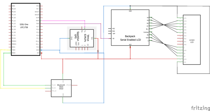
| + | The following diagram captures how all the modules of the application device were interfaced: | ||
| + | [[File:cmpe244_s14_am_hardware_schematic.png|700px|center|Schematic]] | ||
| + | |||
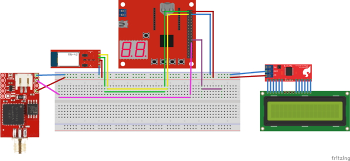
| + | The diagram below shows the breadboard prototype of the final product: | ||
| + | [[File:cmpe244_s14_am_breadboard_prototype.png|center|700px|Breadboard Prototype]] | ||
| + | |||
| + | As mentioned earlier, the tile device was simply a Bluetooth module connected to a coin cell battery. | ||
| + | |||
| + | === Hardware Implementation === | ||
| + | |||
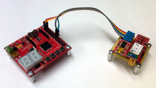
| + | Engineering Prototype - Implemented with a drop in replacement so the LCD output is adjusted for a console display over USB. Other than the LCD display being replaced by an FT232 device, this design is exactly the same as illustrated in the hardware design section. | ||
| + | |||
| + | [[File:cmpe244_s14_am_engineering_prototype.png|center|500px|Engineering Prototype]] | ||
| + | |||
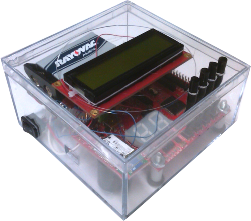
| + | Demonstration Prototype - To demonstrate the functionality of the system, a demonstration prototype was developed to present the system to an audience of engineers. All hardware is enclosed and runs on an independent power supply. | ||
| + | |||
| + | [[File:cmpe244_s14_am_demo_prototype.png|center|500px|Demonstration Prototype]] | ||
| + | |||
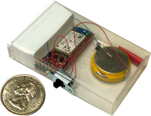
| + | Tile Prototype - The tile prototype is a Bluetooth Module connected to a battery source that can be independently operated. This prototype is also enclosed with the intention to be used for demonstration purposes. | ||
| + | |||
| + | [[File:cmpe244_s14_am_tile_prototype.png|center|300px|Tile Prototype]] | ||
=== Hardware Interface === | === Hardware Interface === | ||
| Line 196: | Line 330: | ||
--> | --> | ||
| − | SJSU One UART3 | + | SJSU One UART3 was interfaced with the Bluetooth module at 115200 bps with RX and TX queue depth of 1024 character elements, respectively using the supplied UART3 driver. Both LCD and GPS modules share UART2 at 9600 bps with RX and TX depth of 1024 character elements. The LCD module was interfaced with the TX of UART2 and the GPS module was interfaced with the RX of UART2. |
The following table depicts the connections: | The following table depicts the connections: | ||
{| class="wikitable" | {| class="wikitable" | ||
| Line 218: | Line 352: | ||
! rowspan = "2" | UART3 | ! rowspan = "2" | UART3 | ||
| TX | | TX | ||
| − | | RX - | + | | RX - I |
|- | |- | ||
| RX | | RX | ||
| Line 235: | Line 369: | ||
| TX | | TX | ||
| RX | | RX | ||
| + | |- | ||
| + | ! Power | ||
| + | | 3.3V | ||
| + | | 3.3V | ||
| + | ! rowspan = "3" | GPS | ||
| + | |- | ||
| + | ! Ground | ||
| + | | GND | ||
| + | | GND | ||
| + | |- | ||
| + | ! UART2 | ||
| + | | RX | ||
| + | | TX | ||
|} | |} | ||
| Line 240: | Line 387: | ||
<!--Show your software design. For example, if you are designing an MP3 Player, show the tasks that you are using, and what they are doing at a high level. Do not show the details of the code. For example, do not show exact code, but you may show psuedocode and fragments of code. Keep in mind that you are showing DESIGN of your software, not the inner workings of it.--> | <!--Show your software design. For example, if you are designing an MP3 Player, show the tasks that you are using, and what they are doing at a high level. Do not show the details of the code. For example, do not show exact code, but you may show psuedocode and fragments of code. Keep in mind that you are showing DESIGN of your software, not the inner workings of it.--> | ||
| − | Asset Management and Location System | + | Asset Management and Location System consisted of four tasks: |
| − | # Switch Task - | + | # Switch Task - Monitored the switches that allowed the user to navigate the user menu. When a switch was pressed, this task enqueued the switch ID to the Asset Management task. This task executed in low priority at 10ms interval. |
| − | # GPS Task - | + | # Asset Management Task - Controlled the LCD (user menu navigation) and Bluetooth module. This task received switch pressed notification from the Switch task. Upon receiving a switch pressed event, this task either updated the user display or initiated a Bluetooth inquiry. It also stored the GPS coordinates of each tile to a file on the flash memory. This task executed in low priority. If Bluetooth inquiry was in progress, this task operated at 1s interval otherwise it blocked on switch pressed event. |
| − | # Asset Management | + | # GPS Task - Fetched the current location from the GPS module and stored it in global variable. This task operated in low priority at 1s interval. |
| − | + | # Map Task - This task executed in low priority at 30s interval. Using the files generated by the Asset Management task, it composed a file that the webpage parsed to plot tile location on Google Maps. | |
The interface between these tasks is described in the figure below: | The interface between these tasks is described in the figure below: | ||
| − | [[File: | + | [[File:Cmpe244_s14_am_tasks.png|center|frame|Task Interaction]] |
| − | The Asset Management task | + | The Asset Management task managed the user menu based on events received from the Switch task. The user menu could be navigated in the following manner: |
| − | [[File: | + | [[File:Cmpe244_s14_am_usermenu.png|center|frame|User Menu]] |
=== Implementation === | === Implementation === | ||
<!--This section includes implementation, but again, not the details, just the high level. For example, you can list the steps it takes to communicate over a sensor, or the steps needed to write a page of memory onto SPI Flash. You can include sub-sections for each of your component implementation.--> | <!--This section includes implementation, but again, not the details, just the high level. For example, you can list the steps it takes to communicate over a sensor, or the steps needed to write a page of memory onto SPI Flash. You can include sub-sections for each of your component implementation.--> | ||
==== LCD ==== | ==== LCD ==== | ||
| − | + | The LCD class represented the LCD module. The main objective of this class was to determine what was displayed and format the data that was displayed on the LCD. Furthermore, it was capable of operating in two modes: | |
# Real Mode: In this mode, all the data was printed to the LCD. | # Real Mode: In this mode, all the data was printed to the LCD. | ||
# Emulation Mode: In this mode, all the data was printed to UART1. The feature allowed multiple members of the team to work on the project even though the team owned single LCD module. | # Emulation Mode: In this mode, all the data was printed to UART1. The feature allowed multiple members of the team to work on the project even though the team owned single LCD module. | ||
| Line 274: | Line 421: | ||
==== Tile Device ==== | ==== Tile Device ==== | ||
| − | The information of each device was stored in the following class. The stored information consisted of MAC address, tile name (identifier selected by the user), Bluetooth name, RSSI value, and class of service identifier. | + | The information of each device was stored in the following class. The stored information consisted of MAC address, tile name (identifier selected by the user), Bluetooth name, RSSI value, and Bluetooth class of service identifier. |
[[File:cmpe244_s14_am_tile_device_class_diagram.png|center|frame|Tile Information Storage]] | [[File:cmpe244_s14_am_tile_device_class_diagram.png|center|frame|Tile Information Storage]] | ||
==== Asset Management ==== | ==== Asset Management ==== | ||
| + | ===== Bluetooth Inquiry ===== | ||
| + | One of the most critical components of the project was Bluetooth inquiry. In hindsight, this functionality should have been implemented in Bluetooth software module. Doing so would change the interface, but the core functionality of the inquiry would remain the same. The Bluetooth inquiry can be best implemented with a state machine. The following diagram lists all the states and the transitions. To enable the user to cancel the inquiry at any time, the Bluetooth inquiry spanned multiple function calls. This required using local static variables to preserve the state. Of course, this means inquiry can't be launched from multiple threads. This was, however, the design that was chosen since Asset Management system has only one main thread. | ||
| + | |||
| + | [[File:cmpe244_s14_am_bt_inquiry.png|center|frame|Bluetooth Inquiry State Machine]] | ||
| + | |||
===== User Menu ===== | ===== User Menu ===== | ||
| − | The update of user menu was triggered by switch press or Bluetooth inquiry state change was made non-blocking operation. This allowed the user the ultimate control of the system behavior. For example, it allowed the user to cancel a Bluetooth inquiry and navigate to the previous menu while Bluetooth inquiry was under way. | + | The update of user menu which was triggered by switch press or Bluetooth inquiry state change was made non-blocking operation. This allowed the user the ultimate control of the system behavior. For example, it allowed the user to cancel a Bluetooth inquiry and navigate to the previous menu while Bluetooth inquiry was under way. In order to support this, however, each menu had to preserve it's state across multiple function calls. |
| − | * Main Menu: This menu just displays all the options that | + | * Main Menu: This menu just displays all the options that were available to the user. |
| − | * Add Tile Menu: This menu | + | * Add Tile Menu: The following flow chart illustrates the add tile operation. When a tile device was added, the tile information was stored in RAM and to a file on the flash memory. |
| + | [[File:cmpe244_s14_am_add_tile.png|center|frame|Add Tile Operation]] | ||
| + | * Remove Tile Menu: This operation was essentially the inverse to add tile operation. | ||
| + | * List Tiles: This menu listed information of all the registered devices to the LCD. The displayed information included: 1) User selected tile name, 2) Bluetooth name, 3) MAC address. | ||
| + | * Time: This menu allowed the user to set the system RTC. The following figure illustrate how the set time menu worked. The diagram ignores the Up and Down buttons because they just change the value. | ||
| + | [[File:cmpe244_s14_am_set_time.png|center|frame|Display/Set Time Operation]] | ||
| + | |||
| + | ==== File Storage ==== | ||
| + | |||
| + | There were 3 set of files that were written: | ||
| + | * This was a single file with name flash:tiles.txt. This file stored information of all the registered tiles and had the following structure: | ||
| + | [[File:cmpe244_s14_am_tile_file_struct.jpg|center|frame|tiles.txt File Structure|center]] | ||
| + | * These were set of files stored in directory flash:gpsdb. Each tile device had a dedicated file that contained the last known GPS data of the tile device. The filename was the MAC address of the tile device. For example, tile device with the MAC address of aa:bb:cc:dd:ee:ff would be stored with full path of flash:gpsdb/aabbccddeeff. This file has the following structure: | ||
| + | Tile Identifier, Bluetooth Name, MAC, Time, Latitude, Longitude | ||
| + | * This was a single file that was stored on the micro SD card. This file was parsed by the webpage to compose Google Maps. This file had the following structure: | ||
| + | <table><tr><td>Tile Identifier 1, Bluetooth Name 1, MAC 1, Time 1, Latitude 1, Longitude 1</td></tr> | ||
| + | <tr><td>Tile Identifier 2, Bluetooth Name 2, MAC 2, Time 2, Latitude 2, Longitude 2</td></tr> | ||
| + | <tr><td>...</td></tr> | ||
| + | <tr><td>Tile Identifier n, Bluetooth Name n, MAC n, Time n, Latitude n, Longitude n</td></tr><table> | ||
| + | |||
| + | The locations of the tiles were displayed on Google Maps as such: | ||
| + | [[File:cmpe244_s14_am_googlemaps.jpg|700px|center|Tile Location on Google Maps]] | ||
| + | |||
| + | ==== GPS ==== | ||
| + | GPS continuously sends a stream of GPS data. The only data that was of concern for this project was the following string: | ||
| + | $GPGGA,111636.932,2447.0949,N,12100.5223,E,1,11,0.8,118.2,M,,,,0000*02<CR><LF> | ||
| + | |||
| + | This string contains: | ||
| + | $GPGGA,UTC Time, Latitude, N/S Indicator, Longitude, E/W Indicator, GPS Quality Indicator, Satellites Used, HDOP, Altitude, DGPS Station ID, Checksum. | ||
| + | |||
| + | This data was only used if the GPS Quality Indictor was more than 1. | ||
== Testing & Technical Challenges == | == Testing & Technical Challenges == | ||
| − | + | The team faced few challenges in the development of Asset Management and Location System: | |
| − | + | === Challenge # 1 === | |
| + | As mentioned earlier in the report, the Bluetooth module had two modes to retrieve RSSI value - RSSI mode and inquiry mode. The RSSI mode provides a RSSI value at a rate of 5Hz. The team bought this module under the assumption that RSSI mode provided an accurate signal strength value. This, however, wasn't the case. To address this issue, inquiry mode was used to acquire the RSSI value. The inquiry mode was much slower however. | ||
| + | |||
| + | === Challenge # 2 === | ||
| + | Furthermore, the Bluetooth module didn't provide an indication of whether it was in command mode or data mode. This wasn't a significant challenge. To address this issue, before issuing a command, a known command with known response was sent. This extra logic could have been eliminated if the Bluetooth module provided a GPIO pin that could have been read to determine which mode the Bluetooth module was in. | ||
| + | |||
| + | === Challenge # 3 === | ||
| + | The Storage APIs are not thread safe. It took few hours for the team to determine this was case. Addressing of this issue was pretty simple. The Storage APIs were encapsulated in mutex lock and unlock. This issue should ultimately be solved in the Storage class. | ||
| − | + | === Challenge # 4 === | |
| + | Nobody in the team had significant experience in web development; therefore, Google Map integration took a while. | ||
| − | === | + | === Primary Test Cases === |
| − | + | {| class="wikitable" | |
| + | |- | ||
| + | ! scope="col"| Test Case # | ||
| + | ! scope="col"| Description | ||
| + | ! scope="col"| Expected Behavior | ||
| + | ! scope="col"| Result | ||
| + | |- | ||
| + | ! scope="row"| 1 | ||
| + | | Search for Tiles. | ||
| + | | Show list of discovered Tiles. | ||
| + | | Passed | ||
| + | |- | ||
| + | ! scope="row"| 2 | ||
| + | | Search for Tiles with none available in vicinity. | ||
| + | | Display message stating no Tiles found. | ||
| + | | Passed | ||
| + | |- | ||
| + | ! scope="row"| 3 | ||
| + | | Add a tile. | ||
| + | | Tile is successfully added. | ||
| + | | Passed | ||
| + | |- | ||
| + | ! scope="row"| 4 | ||
| + | | Add more than one tile. | ||
| + | | Multiple tiles added in succession. | ||
| + | | Passed | ||
| + | |- | ||
| + | ! scope="row"| 5 | ||
| + | | List added tiles. | ||
| + | | Display list of Tile assigned names, actual names, and MAC addresses. | ||
| + | | Passed | ||
| + | |- | ||
| + | ! scope="row"| 6 | ||
| + | | Track a tile. | ||
| + | | Initiate tracking sequence and display RSSI value with proximity gauge. | ||
| + | | Passed. | ||
| + | |- | ||
| + | ! scope="row"| 7 | ||
| + | | Select a second tile to track. | ||
| + | | Tracking should display information for different tile. | ||
| + | | Passed | ||
| + | |- | ||
| + | ! scope="row"| 8 | ||
| + | | Exit tracking state. | ||
| + | | Return to user menu interface, one level up. | ||
| + | | Passed | ||
| + | |- | ||
| + | ! scope="row"| 9 | ||
| + | | Exit Tile search state. | ||
| + | | Return back to user menu interface. | ||
| + | | Passed | ||
| + | |- | ||
| + | ! scope="row"| 10 | ||
| + | | Remove a Tile. | ||
| + | | Tile entry should be removed with success message, should not be shown in listed/track-able devices. | ||
| + | | Passed | ||
| + | |- | ||
| + | ! scope="row"| 11 | ||
| + | | Seamless navigation of user menu interface. | ||
| + | | User should be able to navigate menu without error. | ||
| + | | Passed | ||
| + | |- | ||
| + | ! scope="row"| 12 | ||
| + | | Clock and calendar set functionality. | ||
| + | | User should be able to set and save data and time on Tracker. | ||
| + | | Passed | ||
| + | |- | ||
| + | ! scope="row"| 13 | ||
| + | | GPS data-logging and display on Google Maps. | ||
| + | | GPS module should log location data and store to micro SD flash card in order to display locations in Google Maps. | ||
| + | | Passed | ||
| + | |} | ||
== Conclusion == | == Conclusion == | ||
| + | |||
| + | <!-- | ||
Conclude your project here. You can recap your testing and problems. You should address the "so what" part here to indicate what you ultimately learnt from this project. How has this project increased your knowledge? | Conclude your project here. You can recap your testing and problems. You should address the "so what" part here to indicate what you ultimately learnt from this project. How has this project increased your knowledge? | ||
| + | --> | ||
| + | |||
| + | Ultimately, we were able to successfully develop a functioning prototype that is comparable to competitive products available on the market today. There were many lessons learned over the course of the project. Some lessons were regarding infrastructure, others regarding operating system topics, and some in manufacturing techniques. Given an opportunity to do the project again, there are many things we would do differently regarding design and implementation. However, overall we are very happy with the results of our project as it is currently passing all test cases. | ||
=== Project Video === | === Project Video === | ||
| Line 299: | Line 565: | ||
=== Project Source Code === | === Project Source Code === | ||
| − | |||
== References == | == References == | ||
| + | |||
| + | === GitLab === | ||
| + | |||
| + | * [https://sourceforge.net/projects/sjsu/files/CmpE244_SJSU_S2014/ Sourceforge source code link] | ||
| + | |||
| + | This project was fully managed and maintained using GitLab. Unlike other Git repository hosting services, GitLab offers unlimited free private repositories that can shared between an unlimited number of users. Additionally, GitLab provides many project management features with a repository - features such as defect tracking, a wiki, chat and messaging systems, plus GitLab can be integrated with many third-party services. | ||
| + | |||
| + | The Git Network photo visually illustrates the develolpment process. The master branch was used as our weekly stable code base, the devel branch was used for all on-going development, and feature branches from devel were used to implement an experimental feature. | ||
| + | |||
| + | [[File:cmpe244_s14_am_git_network.png|700px|center|Git Network]] | ||
| + | |||
| + | By using Git to manage our project the team faced very few issues regarding project management and code sharing. Additionally, features provided by GitLab allowed us to privately document development workflows in the wiki and conduct code reviews between the team. This team highly recomends GitLab as a platform for students to work on team projects - it provides a complete project management solution with a clean and simple interface. | ||
| + | |||
=== Acknowledgement === | === Acknowledgement === | ||
Any acknowledgement that you may wish to provide can be included here. | Any acknowledgement that you may wish to provide can be included here. | ||
=== References Used === | === References Used === | ||
| + | |||
| + | <!-- | ||
List any references used in project. | List any references used in project. | ||
| + | --> | ||
| + | |||
| + | [http://inburst.io/bluetooth-rssi-to-actual-distance/ Bluetooth to RSSI Actual Distance] - One part of this project was to convert RSSI values into a histogram which accurately represented distance. There are many formulas to do so, but even with the additional computation the precision of the distance was low. This blog post demonstrated that RSSI values can be measured and can be converted to a rough estimate. After reading this blog post we conducted our own RSSI-to-Distance measurements using our own hardware; with that data we were able to generate a histogram with reduced computation and acceptable precision. | ||
| + | |||
| + | [http://www.thetileapp.com/ The Tile App] - This product was the inspiration of this project. We used all of the available online marketing material for Tile to research and reverse engineer parts of the existing product. Although we aimed to replicate many of the features available in the commercial product, this project was independently created. It is unlikely that the two solutions share any of the same parts, manufacturing process, or code. | ||
=== Appendix === | === Appendix === | ||
You can list the references you used. | You can list the references you used. | ||
Latest revision as of 23:41, 6 August 2014
Contents
- 1 S14: Asset Management and Location System
- 2 Abstract
- 3 Objectives & Introduction
- 4 Schedule
- 5 Parts List & Cost
- 6 Design & Implementation
- 7 Testing & Technical Challenges
- 8 Conclusion
- 9 References
S14: Asset Management and Location System
Abstract
The ultimate vision of this project was to develop an asset management and location system to compete with The Tile App. There were two major components to the Tile solution: the tile and the application. The tile was small low-power embedded system that could be attached to an object. The application was primarily a user interface that provides visual feedback to guide a user to a specified tag.
For this project, the tile is simply a Bluetooth module powered by a coin cell battery. The management unit, on the other hand, consists of:
- SJ One development board
- LCD
- Bluetooth module
- GPS module
The system used the Bluetooth RSSI value to determine proximity of the application device to the tile device. SJ One board communicated proximity to the user via a histogram that was displayed on the LCD. If the tile device was within the expected proximity, the GPS coordinates of the tile device were written to a file on the SC card. A webpage was developed which would read this file and plot the tile location of know tiles on Google Maps.
Complete feature set of Asset Management and Location System enabled the following:
- Locating/tracking a tile
- Adding/registering a new tile
- Removing a tile
- Listing all the registered tiles
- Updating the RTC
- Displaying the last known location of tiles on Google Maps
Objectives & Introduction
Objectives
- To track a tile location within 100 meters
- To add/register tiles to user
- To remove tiles from user tiles database
- To display a histogram of tile vicinity
- To display last known location on Google Maps
Team Members & Responsibilities
- Akash Ayare - Feature development
- Pardeep Badhan - Feature development
- Talha Ilyas - Packaging and feature unit testing
Schedule
Show a simple table or figures that show your scheduled as planned before you started working on the project. Then in another table column, write down the actual schedule so that readers can see the planned vs. actual goals. The point of the schedule is for readers to assess how to pace themselves if they are doing a similar project.
| Week | Date | Planned | Actual |
|---|---|---|---|
| 1 | 3/6 | Create Wiki page and add the schedule of the project. | Wiki page was created and preliminary scheduling was added. |
| 2 | 3/13 | Research on Bluetooth and Zigbee radio technologies. | Compared Bluetooth and Zigbee range and power consumption.
Although Zigbee has slightly better power consumption and better range, decision was made to use Bluetooth for the project to keep similarity with Tile project. |
| 3 | 3/20 | Order parts and research RSSI | Parts were not ordered mainly due to the number of options available; more research was still needed.
Instead, the team registered with GitLab. Project "lpc1758_freertos" was checked in as the base project. Furthermore, the team trained on Git workflow and branching methodology. |
| 4 | 3/27 | Interface Bluetooth Modules. | Ordered Class 1 Bluetooth version 2 modules. |
| 5 | 4/3 | Achieve basic Bluetooth communication. | Basic connectivity achieved.
Hercules Setup software was used to connect to the Bluetooth Serial port. |
| 6 | 4/10 | Fetch RSSI value from the Bluetooth module. | Discovered there are two ways to fetch the RSSI value. One mode worked better over the other, but it was slower. In a open room, with one of the modes, there wasn't significant change in RSSI value when proximity changed. The second mode provided better distance estimation, but it was slower to fetch RSSI value in this mode. |
| 7 | 4/17 | Experiment how this value changes with proximity. | Started interfacing with the Bluetooth module with SJ One Board instead of Hercules.
Also, added a task to receive Bluetooth data and display it on console. |
| 8 | 4/24 | Implement visual indicator (histogram) corresponding to RSSI values. | Interfaced LCD screen with SJ One Board.
Added tasks to control the user menu and monitor switches, and user menu infrastructure that:
|
| 9 | 5/1 | Packaging, battery installation, and testing. Expansion of feature-set. | Enhanced features:
|
| 10 | 5/8 | Demo | The demo was postponed to 05/22
Enhanced features:
|
| 11 | 5/15 | Final Exams, Additional week for bug fixing, testing, and packaging. | Fixed bugs:
Enhanced features:
|
| 12 | 5/22 | Demo and report submission. | More feature development:
|
Parts List & Cost
| Item | Part Name | Part Cost | Qty | Total Cost |
|---|---|---|---|---|
| 1 | LPC1758 SJSU One Board | $80 | 1 | $80 |
| 2 | SparkFun BlueSMiRF Gold] | $64.95 | 2 | $209.90 |
| 3 | SparkFun Bluetooh Mate Gold | $64.95 | 1 | $274.85 |
| 4 | Serial Enabled 16x2 LCD | $24.95 | 1 | $299.80 |
| 5 | Venus GPS Logger with SMA Connector | $59.95 | 1 | $359.75 |
| 6 | Antenna GPS Embedded SMA | $11.95 | 1 | $371.70 |
| 7 | Philmore Micro Rocker Switch | $1.99 | 1 | $373.69 |
| 8 | SPDT Sub-Mini Slide Switch 2-Pack | $3.99 | 1 | $377.68 |
| 9 | Tile Enclosure | $0.98 | 2 | $379.64 |
| 10 | Tracker Enclosure | $4.99 (+ $11.99 fabrication) | 1 | $396.62 |
| 10 | 9V Battery | $4.99 | 2 | $406.60 |
| 11 | Philmore 9V Snap-In Battery Holder | $0.89 | 1 | $407.49 |
| 12 | 24.5mm Coin Cell Battery | $2.95 | 2 | $413.39 |
| 13 | 12mm Coin Cell Battery | $1.99 | 1 | $415.38 |
| 14 | Fabricated Button Extensions | $0.99 | 1 | $416.37 |
| 15 | Micro SD Card | $9.99 | 1 | $426.36 (tax + shipping not included) |
Design & Implementation
Components
LPC1758 SJSU One Development Board
The SJSU One Development Board serves as the management system behind the functionality of the Tracker device. The utilization of the hardware (primarily UART interfaces) along with the strengths of FreeRTOS for task scheduling capabilities provide for a solid foundation for the Tracker's proposed features. The SJSU One Board is intergrated with Bluetooth, LCD, and GPS peripheral devices. Power is supplied to the peripheral devices by the SJSU One Board. The Bluetooth module TX and RX are interfaced with the SJSU One Board's UART3 for command issuance/execution and data parsing capabilities. The LCD and GPS modules are interfaced with UART2 of the SJSU One Board in order for appropriate display output and Google Map functionality integration, respectively.
Power Supplies
The Tracker device is powered by a 9V battery circuit with a micro rocker switch, which in-turn indirectly power the Tracker's peripheral devices through the SJSU One Board. The Tile module is powered by a 3.6V 24.5mm coin cell battery inline with a slider switch (to maximize battery life during development and testing) which is connected to a Bluetooth module.
Bluetooth Mate/BlueSMiRF Gold
The Bluetooth module is interfaced to UART 3 for the Tracker system and provides for communications between the user and the Bluetooth module. In detail, it allows for the user commands to be input through the push-buttons and the corresponding software serially communicates the appropriate commands and actions to the Bluetooth module. The Bluetooth module within the Tile device is simply powered by a battery and only communicates to other devices (i.e. Tracker) through the Bluetooth protocol. The Bluetooth module in the Tracker utilizes Bluetooth to communicate with all potential Tiles and Bluetooth devices wirelessly through the Bluetooth protocol, but provides serial I/O to the SJSU One Board via UART.
Serial Enabled 16x2 LCD
The LCD module is interfaced to UART2 TX on the SJSU One Board in order to provide the user a menu-based interface to select certain actions for the Tracker to deploy and for feedback/stored information. The LCD in conjunction with the on-board push-buttons allow for the user to fully realize Tracker features (i.e. Add, Remove, Track, and List Tiles, among other functionality.
Venus GPS Logger with SMA Connector
The GPS module is interfaced with UART2 RX on the SJSU One Board in order to provide location based data information the the SJSU One Board whenever a signal is available (used in conjunction with the Antenna GPS Embedded SMA). The GPS contains data-logging capabilities and can store to the Micro SD Flash Memory Card whenever the (via application code) whenever signal is established. The data can then be used from the memory card to view locations in Google Maps.
Hardware Design
The following diagram captures how all the modules of the application device were interfaced:
The diagram below shows the breadboard prototype of the final product:
As mentioned earlier, the tile device was simply a Bluetooth module connected to a coin cell battery.
Hardware Implementation
Engineering Prototype - Implemented with a drop in replacement so the LCD output is adjusted for a console display over USB. Other than the LCD display being replaced by an FT232 device, this design is exactly the same as illustrated in the hardware design section.
Demonstration Prototype - To demonstrate the functionality of the system, a demonstration prototype was developed to present the system to an audience of engineers. All hardware is enclosed and runs on an independent power supply.
Tile Prototype - The tile prototype is a Bluetooth Module connected to a battery source that can be independently operated. This prototype is also enclosed with the intention to be used for demonstration purposes.
Hardware Interface
SJSU One UART3 was interfaced with the Bluetooth module at 115200 bps with RX and TX queue depth of 1024 character elements, respectively using the supplied UART3 driver. Both LCD and GPS modules share UART2 at 9600 bps with RX and TX depth of 1024 character elements. The LCD module was interfaced with the TX of UART2 and the GPS module was interfaced with the RX of UART2. The following table depicts the connections:
| SJSU One | Peripheral | ||
|---|---|---|---|
| Power | 3.3V | VCC | Bluetooth |
| Ground | GND | GND | |
| N/A | CTS-I | RTS | |
| UART3 | TX | RX - I | |
| RX | TX - O | ||
| Power | 3.3V | VCC | LCD |
| Ground | GND | GND | |
| UART2 | TX | RX | |
| Power | 3.3V | 3.3V | GPS |
| Ground | GND | GND | |
| UART2 | RX | TX | |
Software Design
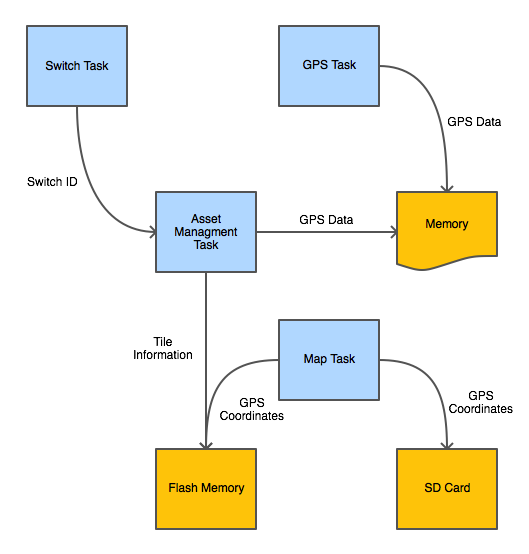
Asset Management and Location System consisted of four tasks:
- Switch Task - Monitored the switches that allowed the user to navigate the user menu. When a switch was pressed, this task enqueued the switch ID to the Asset Management task. This task executed in low priority at 10ms interval.
- Asset Management Task - Controlled the LCD (user menu navigation) and Bluetooth module. This task received switch pressed notification from the Switch task. Upon receiving a switch pressed event, this task either updated the user display or initiated a Bluetooth inquiry. It also stored the GPS coordinates of each tile to a file on the flash memory. This task executed in low priority. If Bluetooth inquiry was in progress, this task operated at 1s interval otherwise it blocked on switch pressed event.
- GPS Task - Fetched the current location from the GPS module and stored it in global variable. This task operated in low priority at 1s interval.
- Map Task - This task executed in low priority at 30s interval. Using the files generated by the Asset Management task, it composed a file that the webpage parsed to plot tile location on Google Maps.
The interface between these tasks is described in the figure below:
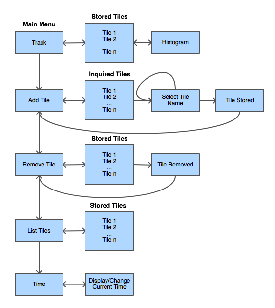
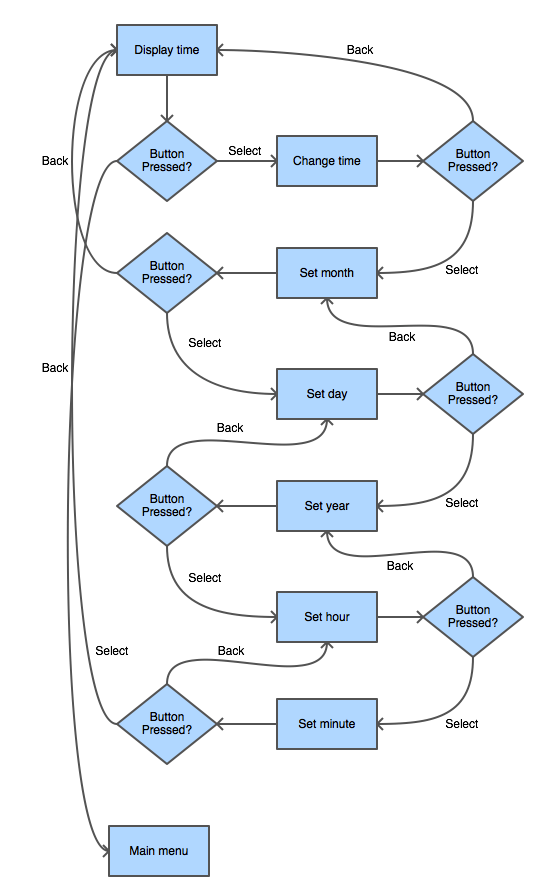
The Asset Management task managed the user menu based on events received from the Switch task. The user menu could be navigated in the following manner:
Implementation
LCD
The LCD class represented the LCD module. The main objective of this class was to determine what was displayed and format the data that was displayed on the LCD. Furthermore, it was capable of operating in two modes:
- Real Mode: In this mode, all the data was printed to the LCD.
- Emulation Mode: In this mode, all the data was printed to UART1. The feature allowed multiple members of the team to work on the project even though the team owned single LCD module.
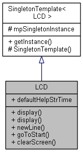
LCD module was represented by singleton design pattern:
Bluetooth
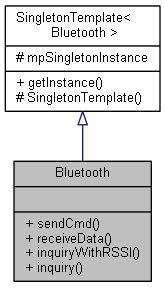
As the name implies, Bluetooth class enabled communication with the Bluetooth module. It provided the following functionality:
- Enter Command Mode: The Bluetooth module used for this project was capable of operating in two modes - 1) data mode and 2) command mode. In the data mode, the Bluetooth module worked as a data pipe and simply converted Bluetooth signals to UART and vice verse. In the command mode, however, the received data (either via Bluetooth or UART) instrumented the Bluetooth module to an operation such as change configuration ("set" commands, return current configuration ("get" commands), etc. The Bluetooth module doesn't have any physical indication of whether the module is in data mode or command mode. To address this issue, this feature issued a "get" command to retrieve the current firmware version of the module. If the expected firmware version was read, it was known that the module was in command mode. If not, an attempt was made to enter the command mode and read the firmware version number. This process repeated until either it eventually exceeded the number of expected tries or it command mode was entered.
- Enter Data Mode: This feature was not used for this project.
- Send Command: This was simply UART TX.
- Receive Data: This was simply UART RX.
The Bluetooth module was represented by singleton design pattern:
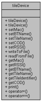
Tile Device
The information of each device was stored in the following class. The stored information consisted of MAC address, tile name (identifier selected by the user), Bluetooth name, RSSI value, and Bluetooth class of service identifier.
Asset Management
Bluetooth Inquiry
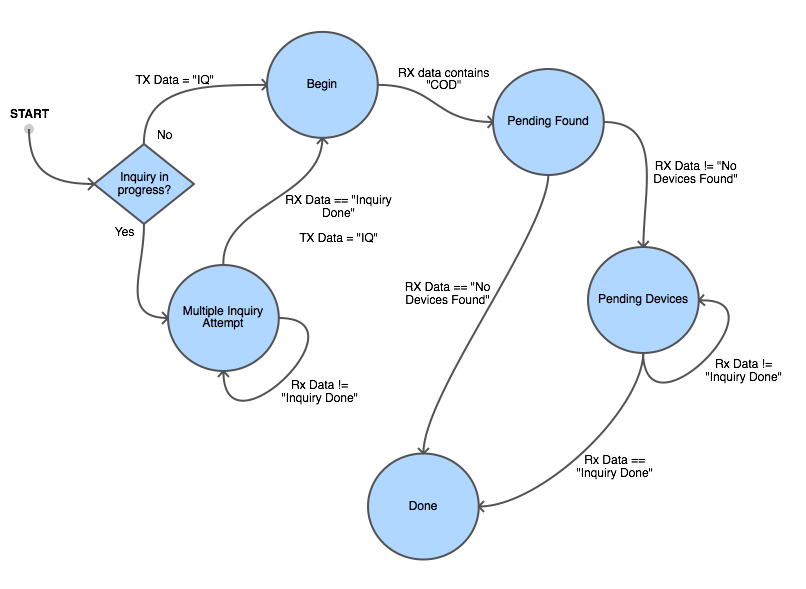
One of the most critical components of the project was Bluetooth inquiry. In hindsight, this functionality should have been implemented in Bluetooth software module. Doing so would change the interface, but the core functionality of the inquiry would remain the same. The Bluetooth inquiry can be best implemented with a state machine. The following diagram lists all the states and the transitions. To enable the user to cancel the inquiry at any time, the Bluetooth inquiry spanned multiple function calls. This required using local static variables to preserve the state. Of course, this means inquiry can't be launched from multiple threads. This was, however, the design that was chosen since Asset Management system has only one main thread.
User Menu
The update of user menu which was triggered by switch press or Bluetooth inquiry state change was made non-blocking operation. This allowed the user the ultimate control of the system behavior. For example, it allowed the user to cancel a Bluetooth inquiry and navigate to the previous menu while Bluetooth inquiry was under way. In order to support this, however, each menu had to preserve it's state across multiple function calls.
- Main Menu: This menu just displays all the options that were available to the user.
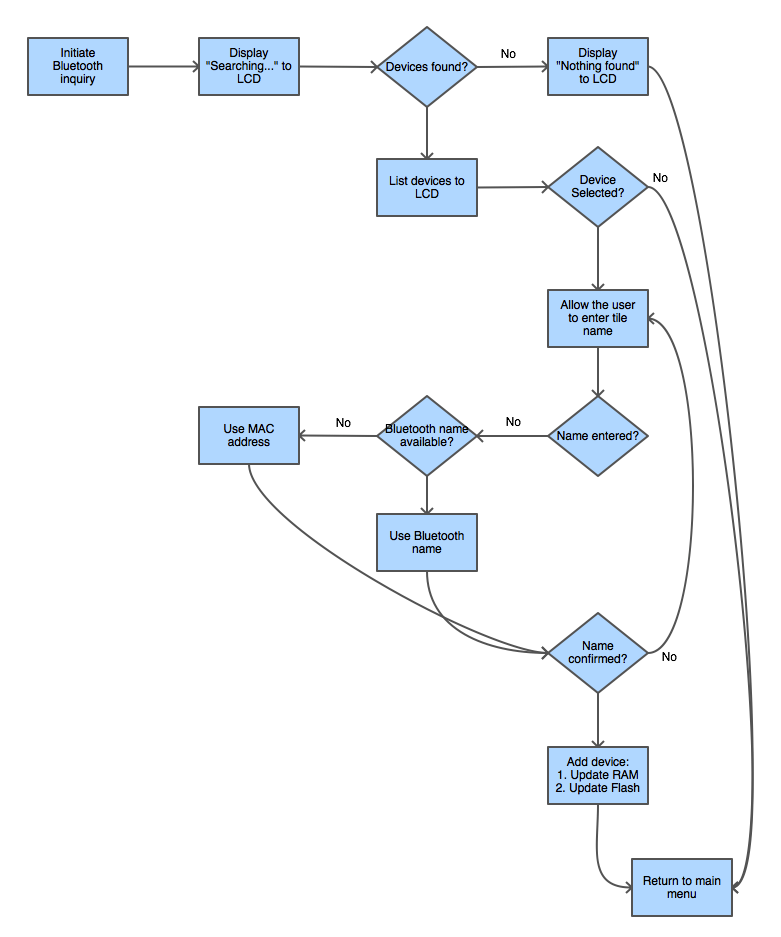
- Add Tile Menu: The following flow chart illustrates the add tile operation. When a tile device was added, the tile information was stored in RAM and to a file on the flash memory.
- Remove Tile Menu: This operation was essentially the inverse to add tile operation.
- List Tiles: This menu listed information of all the registered devices to the LCD. The displayed information included: 1) User selected tile name, 2) Bluetooth name, 3) MAC address.
- Time: This menu allowed the user to set the system RTC. The following figure illustrate how the set time menu worked. The diagram ignores the Up and Down buttons because they just change the value.
File Storage
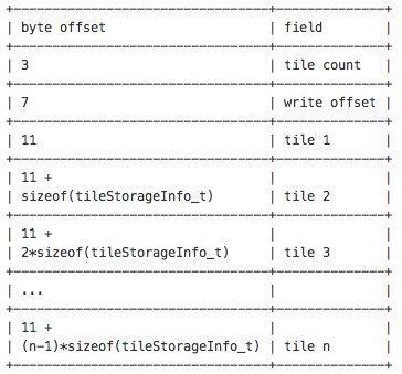
There were 3 set of files that were written:
- This was a single file with name flash:tiles.txt. This file stored information of all the registered tiles and had the following structure:
- These were set of files stored in directory flash:gpsdb. Each tile device had a dedicated file that contained the last known GPS data of the tile device. The filename was the MAC address of the tile device. For example, tile device with the MAC address of aa:bb:cc:dd:ee:ff would be stored with full path of flash:gpsdb/aabbccddeeff. This file has the following structure:
Tile Identifier, Bluetooth Name, MAC, Time, Latitude, Longitude
- This was a single file that was stored on the micro SD card. This file was parsed by the webpage to compose Google Maps. This file had the following structure:
| Tile Identifier 1, Bluetooth Name 1, MAC 1, Time 1, Latitude 1, Longitude 1 | |||
| Tile Identifier 2, Bluetooth Name 2, MAC 2, Time 2, Latitude 2, Longitude 2 | |||
| ... | |||
| Tile Identifier n, Bluetooth Name n, MAC n, Time n, Latitude n, Longitude n |
| Test Case # | Description | Expected Behavior | Result |
|---|---|---|---|
| 1 | Search for Tiles. | Show list of discovered Tiles. | Passed |
| 2 | Search for Tiles with none available in vicinity. | Display message stating no Tiles found. | Passed |
| 3 | Add a tile. | Tile is successfully added. | Passed |
| 4 | Add more than one tile. | Multiple tiles added in succession. | Passed |
| 5 | List added tiles. | Display list of Tile assigned names, actual names, and MAC addresses. | Passed |
| 6 | Track a tile. | Initiate tracking sequence and display RSSI value with proximity gauge. | Passed. |
| 7 | Select a second tile to track. | Tracking should display information for different tile. | Passed |
| 8 | Exit tracking state. | Return to user menu interface, one level up. | Passed |
| 9 | Exit Tile search state. | Return back to user menu interface. | Passed |
| 10 | Remove a Tile. | Tile entry should be removed with success message, should not be shown in listed/track-able devices. | Passed |
| 11 | Seamless navigation of user menu interface. | User should be able to navigate menu without error. | Passed |
| 12 | Clock and calendar set functionality. | User should be able to set and save data and time on Tracker. | Passed |
| 13 | GPS data-logging and display on Google Maps. | GPS module should log location data and store to micro SD flash card in order to display locations in Google Maps. | Passed |
Conclusion
Ultimately, we were able to successfully develop a functioning prototype that is comparable to competitive products available on the market today. There were many lessons learned over the course of the project. Some lessons were regarding infrastructure, others regarding operating system topics, and some in manufacturing techniques. Given an opportunity to do the project again, there are many things we would do differently regarding design and implementation. However, overall we are very happy with the results of our project as it is currently passing all test cases.
Project Video
Upload a video of your project and post the link here.
Project Source Code
References
GitLab
This project was fully managed and maintained using GitLab. Unlike other Git repository hosting services, GitLab offers unlimited free private repositories that can shared between an unlimited number of users. Additionally, GitLab provides many project management features with a repository - features such as defect tracking, a wiki, chat and messaging systems, plus GitLab can be integrated with many third-party services.
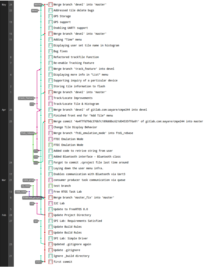
The Git Network photo visually illustrates the develolpment process. The master branch was used as our weekly stable code base, the devel branch was used for all on-going development, and feature branches from devel were used to implement an experimental feature.
By using Git to manage our project the team faced very few issues regarding project management and code sharing. Additionally, features provided by GitLab allowed us to privately document development workflows in the wiki and conduct code reviews between the team. This team highly recomends GitLab as a platform for students to work on team projects - it provides a complete project management solution with a clean and simple interface.
Acknowledgement
Any acknowledgement that you may wish to provide can be included here.
References Used
Bluetooth to RSSI Actual Distance - One part of this project was to convert RSSI values into a histogram which accurately represented distance. There are many formulas to do so, but even with the additional computation the precision of the distance was low. This blog post demonstrated that RSSI values can be measured and can be converted to a rough estimate. After reading this blog post we conducted our own RSSI-to-Distance measurements using our own hardware; with that data we were able to generate a histogram with reduced computation and acceptable precision.
The Tile App - This product was the inspiration of this project. We used all of the available online marketing material for Tile to research and reverse engineer parts of the existing product. Although we aimed to replicate many of the features available in the commercial product, this project was independently created. It is unlikely that the two solutions share any of the same parts, manufacturing process, or code.
